Gardner Bender Sidewinder B2555 Series User manual

1
Read and understand this material before operating or servicing this bender. Failure to understand how to safely operate
and service this unit could result in serious injury or death.
This manual is free of charge. All personnel who operate this Bender should have a copy of this manual and read and
understand its contents. To request a copy, call or write to the address below.
SAFETY ISSUES
B2555 Series Electric
Sidewinder®Bender
Instruction Sheet
1.0 Safety Symbol Definitions . . . . . . . . . . . . . . . . . . . . . . . . . 2
2.0 Important Safety Information . . . . . . . . . . . . . . . . . . . . . . . 2
3.0 Specifications – B2555 Series Electric Bender . . . . . . . . . 2
4.0 Model Descriptions. . . . . . . . . . . . . . . . . . . . . . . . . . . . . . . 3
5.0 Features. . . . . . . . . . . . . . . . . . . . . . . . . . . . . . . . . . . . . . . . 3
5.1SpecialFeatures..............................3
6.0 Shoe Groups . . . . . . . . . . . . . . . . . . . . . . . . . . . . . . . . . . . . 4
7.0 Conduit Centerline Bending Radii . . . . . . . . . . . . . . . . . . . 4
8.0 Grounding Instructions. . . . . . . . . . . . . . . . . . . . . . . . . . . . 5
9.0 Mounting Bending Shoes . . . . . . . . . . . . . . . . . . . . . . . . . . 5
10.0 Mounting Support Rollers & Support Units . . . . . . . . . . . . 6
11.0 Mounting Instructions for Greenlee®Shoes & Attachments. . 6
12.0 General Bending Instructions. . . . . . . . . . . . . . . . . . . . . . . 6
13.0 Bending Instructions for 1-1/2" and 2" EMT & IMC . . . . . . . . 7
14.0 Squeeze Adjustment for 1-1/2" and 2" EMT & IMC . . . . . . 7-8
15.0 Maintenance....................................8
16.0 Stub-Up Bending Information and Charts. . . . . . . . . . . 8-9
17.0 Offset Bending Information and Charts. . . . . . . . . . . . . . 10
18.0 Troubleshooting ................................11
B2555
www.gardnerbender.com
PO Box 3241 Milwaukee, WI 53201-3241 | 414.352.4160 | fax 414.352.2377
6615 Ordan Drive | Mississauga, Ontario L5T 1x2 | 905.564.5749 | fax 905.564.0305
IS_002 | September 2009

2
APPLICATION
1.0 SAFETY SYMBOL DEFINITIONS
THIS SAFETY SYMBOL is used to call your attention to instructions
that concern your personal safety. It means: ATTENTION! BE
AWARE! THIS IS AN IMPORTANT SAFETY INSTRUCTION!
Read, understand, and follow these safety instructions. Failure to
follow these safety instructions may result in injury or death.
DANGER: Immediate hazards which, if not avoided, WILL result
in severe injury or death.
WARNING: Hazards or unsafe practices which, if not avoided,
COULD result in serious personal injury or death.
CAUTION: Hazards or unsafe practices which, if not avoided,
COULD result in minor personal injury or property damage.
2.0 IMPORTANT SAFETY
INFORMATION
Follow ALL safety information provided by the manufacturer.
Read and understand the instruction sheet before
setting up or operating this machine.
DANGER: NEVER operate the bender in an explosive atmosphere.
WARNING: NEVER operate the bender in wet or damp locations.
WARNING: Do NOT expose the bender to rain.
WARNING: ALWAYS use 120 VAC, 20 AMP ground fault
protected receptacle for power supply that is properly installed and
meets all applicable electrical codes. See grounding instructions on
page 3.
WARNING: ALWAYS inspect power cord before using bender.
WARNING: Replace damaged or worn cords.
WARNING: ALWAYS disconnect bender before servicing.
WARNING: ALWAYS make sure switch is in the off position before
plugging in. This will reduce the risk of unintentional starting.
WARNING: Do NOT modify the plug provided with the bender.
WARNING: ALWAYS use 12-gauge extension cords that have
three prong grounding type plugs and three-hole receptacles that
accept the bender’s plug. Do NOT use an adapter.
WARNING: NEVER use an extension cord longer than 100 feet.
WARNING: ALWAYS replace damaged extension cords.
WARNING: ALWAYS disconnect the bender before servicing or
changing shoes, attachments or supports, and when not in use.
WARNING: ALWAYS inspect the bender before operating.
Replace any damaged, missing or worn parts.
WARNING: NEVER alter this equipment. Doing so will void the
warranty.
WARNING: NEVER remove guards, they are installed for your
protection.
WARNING: ALWAYS check for damaged or worn parts. Before
further use of the tool a guard or other part that is damaged should
be carefully checked to determine that it will operate properly and
perform its intended function. Check for alignment of moving parts,
binding of moving parts, breakage of parts, mounting and any other
conditions that may affect its operation. A guard or other part that is
damaged should be properly repaired or replaced.
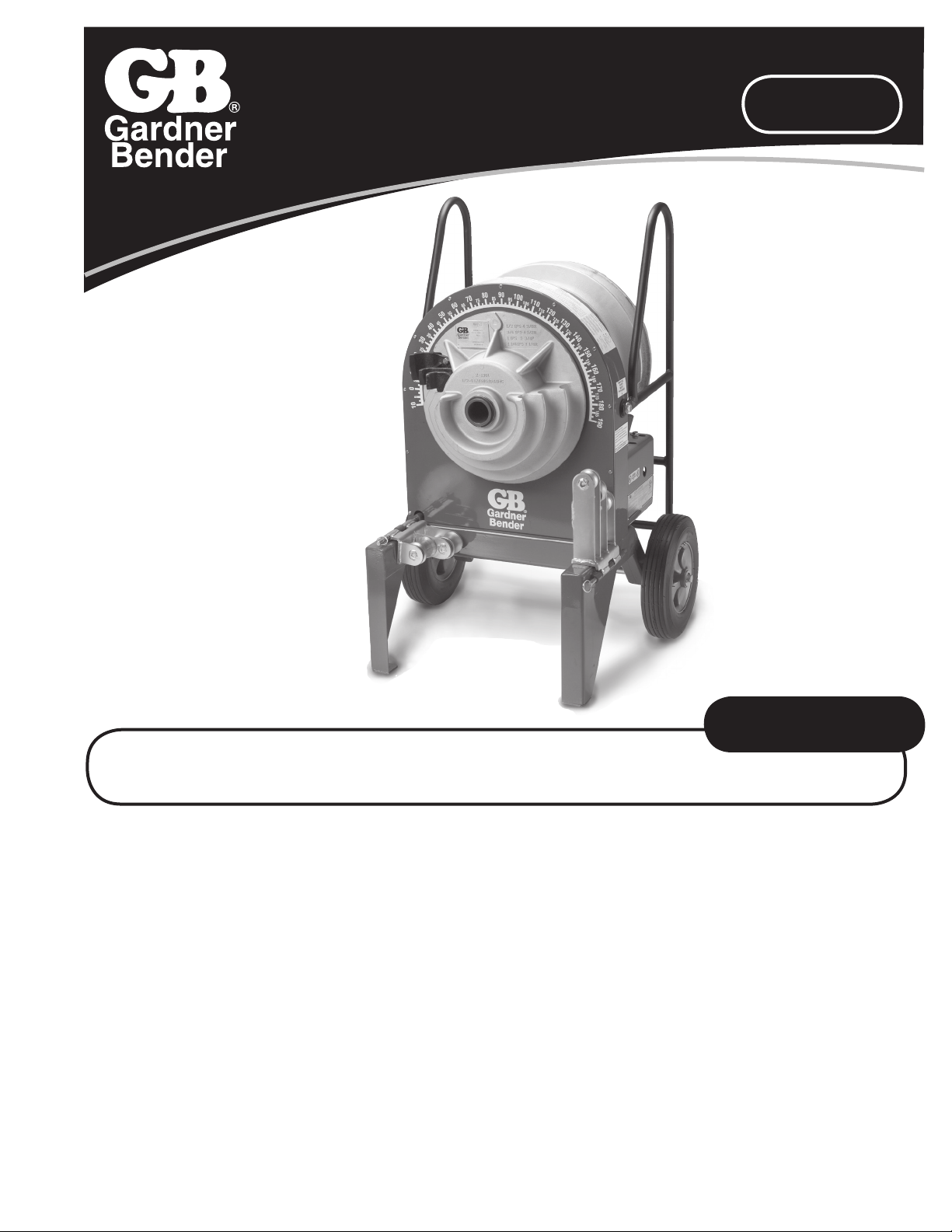
No modification to the
B2555 POWER UNIT is
required to accommodate
these shoes or rollers.
No tools are required to
install or remove these
shoes and roller supports.
WARNING: ALWAYS use recommended accessories. Consult
this manual for recommended accessories. The use of improper
accessories may cause risk of injury.
WARNING: ALWAYS keep hands and feet away from pinch points
such as bending shoes, rollers and conduit when bender is in use.
WARNING: Operator must ALWAYS face the front of the bender
with the bending degree scale visible and maintain a minimum of
3 feet distance while the conduit is being bent. All other personnel
must remain out of the area while the bender is in operation.
WARNING: ALWAYS use appropriate shoe groove and roller
support for the type and size conduit to be bent.
WARNING: If bending shoe will not turn, STOP unit and unplug
before checking for any obstructions.
WARNING: Do NOT use bender or attachment to do a job for
which it was not designed.
WARNING: ALWAYS keep conduit under control when unloading.
WARNING: ALWAYS keep the path of the bending conduit clear
of obstructions. Make sure all obstacles are clear of the bending
path BEFORE you bend the conduit.
WARNING: Be sure handle is bolted securely to the bender frame
before moving or lifting the bender.
WARNING: NEVER stand on bender. Serious injury could occur
if the bender is tipped or if the bending shoe is unintentionally
contacted.
WARNING: ALWAYS wear approved safety glasses when the
bender is in operation.
WARNING: ALWAYS wear proper apparel. Do not wear loose
clothing, gloves, neckties, rings, bracelets, or other jewelry which
may get caught in moving parts. Non-slip footwear is recommended.
Wear protective hair covering to contain long hair.
WARNING: ALWAYS keep children away. All visitors should be
kept a safe distance from work area.
WARNING: ALWAYS make bender childproof with lockouts,
master switches or by unplugging unit.
CAUTION: The bender and some accessories exceed 50 lbs.
and will require more than one person to lift, transport and assemble.
CAUTION: Only use the bender for its intended purpose as
specified in this manual.
CAUTION: ALWAYS use this bender in a dry, well lighted area.
CAUTION: ALWAYS maintain bender with care. Keep bender
clean for best and safest performance.
3.0 SPECIFICATIONS – B2555
SERIES ELECTRIC BENDER
1/2" thru 2" RIGID conduit
1/2" thru 2" EMT conduit
1/2" thru 2" IMC conduit
1/2" thru 2" 40 mil PVC coated
RIGID conduit
1/2" thru 2" schedule 40 steel pipe
The B2555 Series Electric Bender is NOT to be used for bending
any conduit or pipe wall thickness above schedule 40 pipe.
Width 29-1/2"
Length 24-3/4"
Height 39"
Weight 256 lbs. Power Unit Only - without shoes

3
4.0 MODEL DESCRIPTIONS
B2555 Electric Bender Power Unit only, without shoes and roller supports
B2555RIG Electric Bender with shoes and roller supports for 1/2" thru 2" RIGID conduit and schedule 40 pipe and 1/2" thru 1-1/4"
IMC conduit
B2555EMT Electric Bender with shoes and roller supports for 1/2" thru 2" EMT conduit
B2555IMC Electric Bender with shoes and roller supports for 1-1/2" and 2" IMC conduit
B2555PVC Electric Bender with shoes and roller supports for 1/2" thru 2" PVC coated RIGID conduit
5.0 FEATURES
1. Bending Degree Scale - easy to read for exact bends.
2. Support Rollers - for supporting the conduit during bending.
3. Hinge Pin - for securing the support rollers.
4. 12 inch Wheels - for easy mobility.
5. D.C. Motor - quiet and strong.
6. Bending Instructions Decal - easy to read for quick reference.
7. Remote Pendant - with 6 foot cord.
( Bend and unload from pendant. )
8. Removable Handle - may be removed or may be pivoted
for dog-leg bends.
9. Back Rails - Protect the back of bender and enable the
bender to be used horizontally.
5.1 SPECIAL FEATURES
The B2555 Series Electric Benders have a unique feature to pivot or remove the handles during a “Dog-Leg Bend.” See Figure 1 below.
WARNING: When replacing handle, be sure to replace screws and nuts and also to tighten securely before moving or transporting.
The B2555 Series Electric Benders may also be used in a horizontal position. The bender can operate in this position as efficiently
as it does in the upright position. See Figure 2 above.
1
2
3
4
5
6
7
9
8
Figure 1
Remove both
screws and nuts
on each side to
remove handle
Remove top
screw and nut
on each side and
loosen the bottom
screws and the
handle will pivot
as shown
Figure 2

4
6.0 SHOE GROUPS
RIGID
1
2
3
4
BRIG-52 – For bending 1/2" thru 2" RIGID conduit, 1/2"
thru 1-1/4" IMC conduit and 1/2" thru 2" schedule 40 pipe
Includes the following four items:
Key Catalog Description
1 RS-5125 1/2" thru 1-1/4" bending shoe
2 RSR-5125 1/2" thru 1-1/4" roller support
3 RS-152 1-1/2" and 2" bending shoe
4 RSR-152 1-1/2" and 2" roller support
IMC
1
2
3
BIMC-152 – For bending 1-1/2" and 2" IMC
Includes the following four items:
Key Catalog Description
1 IS-15 1-1/2" bending shoe
2 IS-2 2" bending shoe
3 ISR-152 1-1/2" thru 2" IMC roller support unit
BX-1 Metal storage box (not shown)
EMT 1
2
3
4
BEMT-52 – For bending 1/2" thru 2" EMT (Thinwall)
Includes the following six items:
Key Catalog Description
1 ES-5125 1/2" thru 1-1/4" bending shoe
2 ESR-5125 1/2" thru 1-1/4" EMT support
3 ES15 1-1/2" bending shoe
4 ES-2 2" bending shoe
5 ESR-152 1-1/2" thru 2" EMT roller support
BX-1 Metal storage box (not shown)
PVC
1
2
3
BPVC-52 – For bending 1/2" thru 2" 40 mil PVC coated RIGID
Includes the following five items:
Key Catalog Description
1 PVS-5125 1/2" thru 1-1/4" bending shoe
2 PVR-5125 1/2" thru 1-1/4" roller support
3 PVS-152 1-1/2" and 2" bending shoe
4 PVR-152 1-1/2" and 2" roller support
BX-1 Metal storage box (not shown)
5
4
Size 1/2" 3/4" 1" 1-1/4" 1-1/2" 2"
EMT 4-1/4" 5-3/8" 6-3/4" 8-3/4" 8-9/32" 9-3/16"
IMC - - - - 8-9/32" 9-3/16"
RIGID 4-3/8" 4-1/2" 5-3/4" 7-1/4" 8-1/4" 9-1/2"
7.0 CONDUIT CENTERLINE BENDING RADII

5
8.0 GROUNDING INSTRUCTIONS
WARNING: ELECTRIC SHOCK HAZARD! Only connect the bender to a 20 AMP GFCI protected circuit. Do NOT modify the plug which
is provided with the unit. Failure to follow these warnings can result in serious injury or death.
Figure 3 Figure 4
RECEPTACLE PLUG
In the event of a malfunction or breakdown, grounding provides a path of least resistance for electric current to reduce the risk of
electric shock. The bender is equipped with an electric cord having an equipment grounding conductor and a grounding plug. Only
connect the bender to a 20 AMP GFCI protected receptacle which is properly installed and grounded to meet all applicable electrical
codes. Do NOT use an adapter.
Do NOT modify the plug provided. If it will not fit the receptacle, have the proper receptacle installed by a qualified electrician.
Improper connection of the equipment grounding conductor can result in risk of electric shock. The conductor with insulation hav-
ing an outer surface that is green with or without yellow stripes is the equipment grounding conductor. If repair or replacement of the
electric cord or plug is necessary, do not connect the equipment grounding conductor to a live terminal.
Check with a qualified electrician or service personnel if the grounding instructions are not completely understood, or if in doubt as to
whether the bender is properly grounded.
Use only 3-wire extension cords that have 3-prong grounding plugs and 3-pole receptacles that accept the bender’s plug.
Repair or replace damaged or worn cord immediately.
This bender is intended for use on a circuit that has a receptacle that looks like the one illustrated in Figure 3 above. The bender has a
grounding plug that looks like the plug illustrated in Figure 4 above.
9.0 MOUNTING BENDING SHOES
Choose desired shoe size and type ( RIGID, IMC, EMT, or 40 mil PVC coated RIGID ) and slide shoe onto the main drive sprocket
shaft. See Figure 5 below.
Sprocket
Shaft
Main Drive
Sprocket
Main
Drive
Sprocket
Bending
Shoe
Drive Studs
Drive Holes
Figure 5 Figure 6
Next, align the four drive studs on the back of the shoe with the four drive holes in the main drive sprocket.
Push the shoe onto the main drive sprocket shaft. See Figure 6.

6
COULD result in minor personal injury or property damage.
10.0 MOUNTING SUPPORT
ROLLERS & SUPPORT UNITS
Choose the desired support unit for corresponding shoe size
and type ( RIGID, IMC, EMT, or 40 mil PVC coated RIGID ). The
appropriate size and type of support unit MUST be used with the
corresponding shoe size and type.
Mount the support unit on the right leg of the bender as you face the
unit. Secure the support unit with the quick release hinge pin. See
Figure 7.
Quick
Release
Hinge Pin
Figure 7
11.0 Mounting Instructions for
Greenlee®Shoes and Attachments
Bending shoes and attachment from Greenlee®555®and 555
Classic®R, E, I ( RIGID, EMT, IMC ) and 40 mil PVC coated RIGID
benders with serial number PL and AAJ will fit the B2555 bender.
All B2555 bending shoes and attachments will fit Greenlee®555®
R, E, I benders with PL and AAJ serial numbers.
* Greenlee®555®and 555 Classic®are registered trademarks of Greenlee/Textron.
12.0 GENERAL BENDING
INSTRUCTIONS
DANGER: NEVER operate this bender in an explosive
atmosphere. Injury or Death may occur.
Bending instructions for:
1/2" thru 2" RIGID conduit
1/2" thru 1-1/4" EMT conduit
1/2" thru 1-1/4" IMC conduit
1/2" thru 2" 40 mil PVC coated RIGID conduit
1/2" thru 2" schedule 40 pipe
See pages 5 and 6 for mounting shoes and support units. Be sure to
match the appropriate shoe with its corresponding support unit.
1. Mark pipe/conduit to desired length. Note that a minimum of
2" from the end of the conduit to the front edge of the hook is
required to eliminate flattening the end of the pipe/conduit. See
Figure 8a.
NOTE: Stub-up and Offset Dimensions can be found on the
Bending Charts on pages 8 thru 10 of this manual or on the bending
instructions decal on top of each bender.
2. Rotate the bending shoe 5 to 10 degrees below the 0 ( zero )
degree setting, as shown in Figure 8b below.
3. After marking the pipe/conduit, place it into the bender. See Figure
8a. The pipe/conduit should slide over the correct size support
unit, through the shoe groove and into the hook. The bending
mark should be at the front ( OUTSIDE ) edge of the hook. See
Figure 8a.
4. Using the remote hand unit ( pendant ), place the “Bend/Unload”
switch in the “bend” position. Press the “Jog” button and advance
the bender. Be sure to check the alignment of the bending mark
as the rotating shoe locks the pipe/conduit into position. Advance
the bender shoe to desired degree of bend. When the pointer on
the shoe reaches the desired degree of bend, release the “Jog”
button and the bender will stop. See Figure 9.
NOTE: Due to springback in pipe/conduit, some over bending is
necessary to achieve the desired degree of bend. See page 9 or
the bending instruction decal on top of each bender for approximate
springback compensation figures.
5. To release the pipe/conduit, place the “Bend/Unload” switch in
the “Unload” position. Press the “Jog” button and reverse the
shoe far enough to release the conduit. Then, rotate the support
unit out of the way. See Figure 9. The pipe/conduit can now be
removed.
WARNING: The pipe/conduit should be under control when
unloading. Failure to do this may result in injury or death.
2"
minimum
Figure 8a Figure 8b
Bending
Mark
Hook
0°
5°
Bending
Mark
Hook
2"
Minimum
90° Bend
Shown
Figure 9
Rotate

7
COULD result in minor personal injury or property damage.
13.0 BENDING INSTRUCTIONS
FOR 1-1/2" AND 2" EMT & IMC
1. See pages 5 and 6 for mounting shoes and support units. Be
sure to match the appropriate shoe with its corresponding
support unit.
NOTE: The outside roller on the 1 1/2” thru 2” IMC support unit is
steel. See Figure 10. The outside roller on the 1 1/2” thru 2” EMT
support unit is urethane. See Figure 11.
2. Mark the conduit to the desired length. Note that a 2” minimum
dimension is required to eliminate flattening the end of the
conduit. See Figure 12.
NOTE: “Stub-up”and “Offset” dimensions can be found on the
bending charts on pages 8 thru 10 of this manual or on the
bending instruction decal located on the top of each bender.
3. Rotate the bending shoe 5 to 10 degrees below the degree
setting. See Figure 8b.
4. After marking the conduit, place it into the bender. The conduit
should slide over the support rollers and through the shoe
groove and into the hook. The bending mark should be at the
front (OUTSIDE) edge of the hook. See Figure 12.
NOTE: The appropriate size and type of support unit MUST be
used with the corresponding shoe size and type.
5. Step on the “Engaging Pedal” which will raise the rollers to
come in contact with the conduit. See Figure 13. Be sure the
correct rollers for the size conduit being bent are in position to
engage the conduit.
NOTE: See SQUEEZE ADJUSTMENT PROCEDURE (Section 14).
Figure 12
2"
minimum
Bending
Mark
Hook
Engaging
Pedal
Figure 9
Rollers shown in raised
(bending) position
6. Keep foot pressure on the engaging pedal and push the
Bend/Unload switch to the Bend position. Then press the Jog
button. The conduit will pull the support rollers against the
stop. Foot pressure can then be removed from the engaging
pedal. Be sure to check the alignment of the bending mark as
the rotating shoe locks the conduit into position.
Advance the bender shoe to the desired degree of bend. When
the pointer on the shoe reaches the desired degree of bend,
release the Jog button and the bender will stop.
NOTE: Due to springback in pipe/conduit, some overbending is
necessary to achieve the desired degree of bend. See page 9 or
the bending instructions decal located on the top of each bender
for approximate springback compensation figures.
NOTE: Do NOT allow the rollers to come in contact with the
bending shoe. The shoe and rollers squeeze the conduit but they
should never touch each other.
7. To release the conduit, place the Bend/Unload switch in the
Unload position. Press the Jog button and reverse the shoe.
The support rollers will then drop, allowing removal of the
conduit.
WARNING: The pipe/conduit should be under control when
unloading. Failure to do this may result in injury or death.
8. After removal of the conduit, inspect it for wrinkling or
excessive side marks. If these conditions occur, refer to the
Squeeze Adjustment Procedure (Section 14).
COULD result in minor personal injury or property damage.
14.0 SQUEEZE ADJUSTMENT
FOR 1-1/2" AND 2" EMT & IMC
The B2555 bender has a Squeeze Adjustment feature if wrinkling
or side marking becomes a problem during the bending process.
This feature allows you to increase or decrease the amount
of pressure applied to the conduit during bending, thereby
eliminating these problems. Begin with the 1/2" starting location
of the adjusting bolts as shown in Figure 14.
1. If wrinkling occurs, pressure against the conduit during the
bending process must increase. To increase the squeeze
(pressure), loosen both set screws and turn both adjusting
bolts one-half turn clockwise. Tighten both set screws and
bend one piece of conduit to test the adjustment. If wrinkling
still occurs, repeat the procedure.
NOTE: Both adjusting bolts MUST be in contact with the bender
frame. See Figure 15 on page 8.
Figure 10 Figure 11
Steel Urethane
IMC SUPPORT UNIT EMT SUPPORT UNIT

8
2. If side marking occurs, or loading IMC or EMT is a problem,
pressure against the conduit during the bending process must
be decreased. To decrease the squeeze ( pressure ), loosen
both set screws and turn both adjusting bolts one-half turn
counter-clockwise. Tighten both set screws and bend one piece
of conduit to test the adjustment. If side marking still occurs,
repeat the procedure.
NOTE: Both adjusting bolts MUST be in contact with the bender
frame.
15.0 MAINTENANCE
WARNING: ALWAYS disconnect power supply before removing
any guards or covers and before servicing this bender. Failure to
do so may result in serious injury or death.
1. The Gear Box is filled with oil at the factory and should not
require periodic flushing. If the Gear Box is opened for repair,
flush by filling the unit with an AGMA #7 oil. Next, run the unit
with no load for 3 minutes. Then, drain and refill the unit with 28
fluid ounces of an AGMA #7 oil such as the ones listed below.
Amoco – Amoco Worm Gear Oil
Chevron – Cylinder Oil 460X
Exxon – CYLESSTIC TK460
Mobil – 600 W Cylinder Oil
Shell – Sun Gear Oil 7C
2. To inspect FRONT #60 chain tension:
• Remove front cover plate.
• To adjust, loosen hex bolt with 3/4 wrench and rotate chain
tensioner toward chain as shown until chain moves no more
than a total of 1/4". See Figure 16.
• Grease chain periodically with a good quality MP grease.
Figure 15
Both Adjusting
Bolts Must Contact
Bender Frame 3. To inspect REAR #40 chain tension:
• Check chain tension after an initial break-in period of 2 - 3 hours
of use and tighten per the instructions below. See Figure 17.
Thereafter, inspect monthly.
• Remove the chain guard by taking out the 2 mounting screws.
• Loosen 8 bolts ( 4 on top and 4 on bottom ) that hold the gear
box in position.
• To tighten chain, move the gear box to the left and
re-tighten bolts.
• For correct tension, chain should deect approximately 1/8".
NOTE: Be sure to keep the gear box and motor in line with
the bender.
• Grease chain periodically with a good quality MP grease.
16.0 STUB-UP BENDING
INFORMATION AND CHARTS
To locate bending marks and springback of 15, 30, 45, 60, and 90
degree bends for a desired stub:
1. Check Chart A, B, or C for deduct length. Note that minimum stub
length is deduct length plus 2".
2. Measure and mark desired stub length on conduit ( stub length
mark ). Subtract “Deduct Length” from this mark and make
a second mark ( bending mark ). See Fig 18a and 18b. Place
bending mark at front edge of shoe hook. See Figure 18c.
Check Chart A, B, or C for springback of desired degree of
bend. Bender should be advanced to this degree to obtain
desired degree of bend.
To Tighten
Chain
Figure 17
4 Bolts on
Bottom
4 Bolts on Top
Chain Guard
Mounting
Screens
Bender Leg
Figure 14
1/2"
Adjusting
Bolt
Set
Screw
Starting
Location of
Adjusting
Bolt
Rotate Chain
Tensioner Upward
to Tighten Chain
Figure 16
1/4" Max
Hex Screw
Chain
Tensioner

9
Stub
Length
Stub
Length
Deduct
Length
Bending Mark
Stub Length
Mark
Figure 18a Figure 18b
Place Bending Mark in Line with
Front Edge of Shoe Hook
Figure 18c
Conduit
Size
Deduct
Length
Springback
15° 30° 45° 60° 90°
1/2" 7" 16-1/4 32-1/2 47-1/2 63-3/4 95
3/4" 8-7/8" 17-1/2 33-3/4 48-3/4 63-3/4 95
1" 10-3/4" 17-1/2 32-1/2 48-3/4 65 95
1-1/4" 13-1/8" 17-1/2 33-3/4 48-3/4 65 95
1-1/2" 13-7/8" 16-1/4 31-1/4 46-1/4 61-1/4 92-1/2
2" 15-3/8" 17-1/2 33-3/4 48-3/4 63-3/4 95
Conduit
Size
Deduct
Length
Springback
15° 30° 45° 60° 90°
1/2" 8-1/2" 20 36-1/4 51-1/4 67-1/2 97-1/2
3/4" 8-1/2" 16-1/4 31-1/4 46-1/4 61-1/4 92-1/2
1" 10" 17-1/2 32-1/2 47-1/2 63-3/4 93-3/4
1-1/4" 12-3/4" 17-1/2 32-1/2 47-1/2 63-3/4 95
1-1/2" 14-1/4" 18-3/4 33-3/4 48-3/4 65 95
2" 16-1/8" 20 35 48-3/4 63-3/4 96-1/4
Conduit
Size
Deduct
Length
Springback
15° 30° 45° 60° 90°
1/2" 8-1/2" 21-1/4 37-1/2 52-1/2 68-3/4 98-3/4
3/4" 8-1/2" 17-1/2 32-1/2 47-1/2 63-3/4 93-3/4
1" 10" 17-1/2 32-1/2 47-1/2 63-3/4 95
1-1/4" 12-3/4" 18-3/4 33-3/4 48-3/4 65 96-1/4
1-1/2" 13-3/4" 17-1/2 33-3/4 48-3/4 63-3/4 95
2" 15-1/4" 20 35 50 65 96-1/4
Chart A – RIGID Conduit/Schedule 40 Pipe
Chart B – EMT Conduit
Chart C – IMC Conduit
NOTE: Springback figures are approximate.
Minimum Stub Length = Deduct Length plus 2"

10
17.0 OFFSET BENDING INFORMATION AND CHARTS
To locate bending marks for a desired offset:
1. Measure distance from end of conduit to start of bend and mark conduit. ( Mark 1 ) See Figure 19b.
2. Refer to chart E for measurement “X” and deduct this distance from Mark 1 and place Mark 2 on conduit.
3. Refer to chart D for center-to-center distance between marks. Measure this distance from Mark 2 and place Mark 3 on conduit.
4. Layout of bends is now complete. Next, place Mark 2 in line with front edge of shoe hook and make first bend. See Figure 19c.
5. Rotate conduit 180 degrees. Place Mark 3 in line with front edge of shoe hook and complete second bend.
To locate center-to-center distance of offset bending marks other than those listed in Chart D, use the following multipliers. Multiply
the height of offset desired by 3.86 on 15 degree bends, 2 on 30 degree bends, and 1.4 on 45 degree bends.
Angle
Figure 19a
Offset
Height
End of Conduit
to Start of Bend
Center to Center
Length
Mark No. 3
Deduct
Length
Mark No. 1
Figure 19b
Place Bending Mark in Line
with Front Edge of Shoe Hook
Figure 19c
Offset Height 2 4 6 8 10 12 14 16 18 20 22
15° Max Conduit Size 3/4" 1-1/2" 2" 2" and smaller
Center-to-Center 7-3/4" 15-7/16" 23-3/16" 30-15/16" 38-5/8" 46-3/8" 54-1/16" 61-13/16" 69-9/16" 77-1/4" 85"
30° Max Conduit Size 3/4" 1" 1-1/2" 2" 2" and smaller
Center-to-Center 8" 12" 16" 20" 24" 28" 32" 36" 40" 44"
45° Max Conduit Size 1/2" 1" 1-1/4" 1-1/2" 2" 2" and smaller
Center-to-Center 8-1/2" 11-5/16" 14-1/8" 16-15/16" 19-13/16" 22-5/8" 25-7/16" 28-1/4" 31-1/8"
Chart D – Offset Height Figures are approximate.
Conduit Size 1/2 3/4 1 1-1/4 1-1/2 2
"X" 3-1/16" 3-1/16" 3-1/16" 4" 4-1/4" 4-1/2"
Chart E Figures are approximate.

11
18.0 TROUBLESHOOTING
WARNING: ALWAYS disconnect power supply before removing any guards or covers and before servicing this bender. Failure to do so
may result in serious injury or death.
Problem Cause Diagnosis Cure
1. Bender will not operate Power source Check for voltage at power
source
If power is on, go to (#3)
2. No power at bender Bad power cord Ohm cord for broken wire Replace cord
3. Power to bender but will not
operate
Circuit breaker / power switch in
the off position
Check power on load side of
breaker to neutral with volt meter
Turn circuit breaker on. If on,
go to next step.
Fuse #1 blown Ohm circuit for short Replace
Control Transformer bad Check voltage in and out, if input
but no output
Replace
Contractor bad Check contacts and ohm coil for
open circuit
Replace
Bridge rectifier bad Check with ohm meter Replace
Switch bad Check with ohm meter Replace
Motor bad Check brushes and ohm for
open or short armature
Replace
4. Motor runs but will not bend Chain from gear box to jack
shaft broken
Remove cover and visually
check for broken parts
Replace
Bad gear box Motor running but no output
through gear box
Replace
Chain from jack shaft to shoe
sprocket broken
Remove cover and visually
check for broken parts
Replace
Key between motor and gear
box missing
Remove motor from gear box Replace key
5. Bender operates in one
direction only
Bad FWD / REV switch Ohm switch for open contact or
shorted contacts
Replace
Bad pendant cord Ohm for broken wire Replace
Bad contactor Check contacts and ohm coil for
open circuit
Replace
6. Contactors chatter Low power to bender Check with amp meter Do not use long drop cords

12
www.gardnerbender.com
PO Box 3241 Milwaukee, WI 53201-3241 | 414.352.4160 | fax 414.352.2377
6615 Ordan Drive | Mississauga, Ontario L5T 1x2 | 905.564.5749 | fax 905.564.0305
IS_002 | September 2009
IMPORTANT: RECEIVING INSTRUCTIONS
Visually inspect all components for shipping damage. If you find damage, notify the carrier at once. Shipping damage is NOT covered by warranty.
The carrier is responsible for all repair or replacement costs resulting from damage in shipment.
REPAIR AND SERVICE INSTRUCTIONS: For repair service and parts contact your nearest Gardner Bender Service Center or refer to enclosed service manuals.
The Gardner Bender Service Center will provide complete and prompt service on all Gardner Bender products.
PARTS AND SERVICE: For quality workmanship and genuine Gardner Bender parts, select an Authorized GB Service Center for your repair needs.
Only repairs performed by an Authorized Service Center displaying the official GB Authorized sign are backed with full
factory warranty. Contact Gardner Bender (414)352-4160 for the name of the nearest GB Authorized Service Center.
WARRANTY: Gardner Bender warrants its product against defects in workmanship and materials for 1 year from date of delivery to user.
Warranty does not cover ordinary wear and tear, abuse, misuse, overloading, altered products or use of improper fluid.
WARRANTY RETURN PROCEDURE: When question of warranty claim arises, send the unit to the nearest GB Authorized Service Center for inspection, transportation prepaid.
Furnish evidence of purchase date. If the claim comes under the terms of our warranty the Authorized Service Center
will REPAIR OR REPLACE PARTS AFFECTED and return the unit prepaid.
Table of contents
Other Gardner Bender Construction Equipment manuals
Popular Construction Equipment manuals by other brands

Fayat Group
Fayat Group DYNAPAC CC1300C instruction manual

PANDROL
PANDROL CD200 IQ Operation and maintenance manual

Dynapac
Dynapac CG223HF instruction manual

Meec tools
Meec tools 251-019 operating instructions

SANY
SANY STG210C-8 Safety, Operation & Maintenance Manual/Parts List

Fayat
Fayat DYNAPAC DRP15D Operating instruction