Part # 4521056 Rev 2 (02/21/12) Page 9
SERVICING
Introduction
Although this appliance has only an on-off switch and
two indicating lamps there is a computerized control to
provide accurate temperature control, fault diagnostics and
low water detection. In most cases of component failure
the control is designed to allow the appliance to continue
operating in a service mode. It is important to understand
the operation of the control and how it reacts to faults in
order to properly diagnose and correct faults.
In order to maintain the safety and accuracy of the appliance
it is also important to closely follow the parts replacement
procedures and inspection guidelines. For safety and
optimum performance use only parts obtained through
Garland or an authorized service agency.
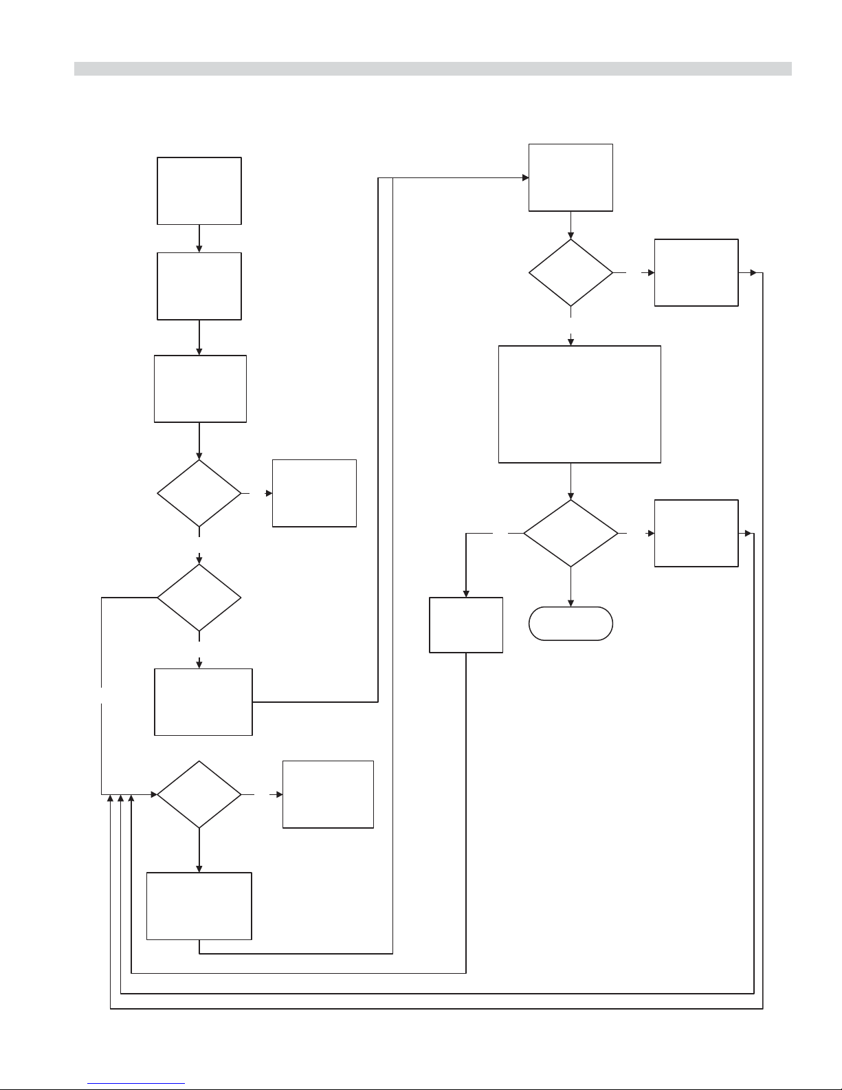
System Block Diagram
Power Supply
Computer
Control
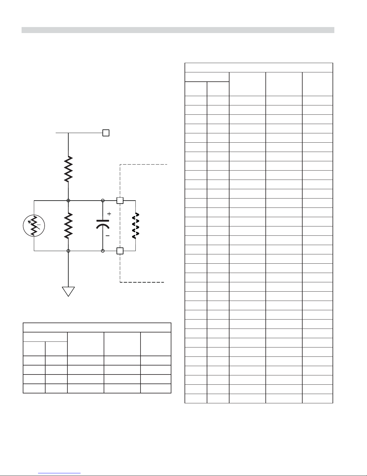
Sensor Input
Indicators
Heater Heater
Tank
Sensor
Service Procedure
When performing any service operations on this equipment
it is important to perform the following inspections to
maintain the performance and safety of the appliance.
Visual Inspection
1. Unplug the unit.
2. Drain the liquid from the tank.
3. Turn the unit over and remove the bottom.
4. Examine the insulation. It should not be moist or wet. Wet
insulation could indicate the unit has been immersed in
water. Assess any potential damage.
5. Remove the bottom insulation. Examine the silicon
heaters. There should be no staining or delamination
from the tank.
6. Examine the high limit thermostats and the position of
the high limit bracket. The bracket is positioned so both
limit thermostats are over the heaters. There should be
no gap between the bracket and the heater. If there
is, remove the bracket and bend it slightly so it makes
contact with the heaters.
7. Look for any loose or damaged wiring.
8. Check fuse FS1.
System Checks
Check the Following in Powered State.
Warning: before applying power make sure the components
are located in a safe manner. Always perform the visual
inspection described above before applying power. Do not
apply power if there is any damage to heaters, wiring or any
components that might compromise safety.
The front control section can be removed from the body by
removing the 4 screws on the sides and loosening the 2 nuts
that attach the front section to the tank.
• Check for a green indicator on the power supply. If there
is no indicator on, check input voltage to the power
supply. If there is 120V AC present at the input terminals
and no output the power supply must be replaced. There
are no serviceable components in the power supply.
• Check the output of the power supply. It should be
12.0V DC ± 0.1V DC. There is a voltage adjustment
potentiometer next to the green indicator. If the power
supply cannot be adjusted to 12.0V DC
± 0.1V DC, it could indicate there is a problem either with
the power supply or the load attached to it (the controller
or sensing circuit). Typically if a voltage regulator is
defective the voltage error will be greater than 2 volts.
• Check the voltage between 12 volt – terminal and the
load side of fuse FS1. 12 volts should be present.
• Check the indicator lamp on the electronic control. In
normal conditions it will be green. If it appears red the
control has malfunctioned. If the indicator is red the
control must be replaced.