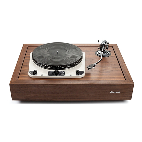
Garrard 210 User manual

RECORD
CHANGER
MODEL
210
THE
CARRARD
ENGINEERING
AND
MANUFACTURING
CO.
LTD
SWINDON
WILTSHIRE
ENGLAND

THE
GARRARDMODEL
210
FOUR
SPEED
RECORD
PLAYER
AND
CHANGER
Introduction
The
Model
210
Record
Player
and
Changer
has
facilities
for
completemanualoperationenabling
it
tobe
used
asa
highqualitysingle
record
player.
There
are
independentcontrols
for
manual
and
automaticoperation.
Should
further
information
be
required
on
yourGarrardunit,please
write
toour
Technical
ServiceDepartment,Newcastle
Street,
Swindon,Wilts.
(Telephone:
Swindon5381-5lines)
or,for
spareparts
and
service
returns,
toour
Service
and
SparesDepartment,50-54RadnorStreet,
Swindon,
Wilts.
(Telephone:
Swindon
2606).
In
U.S.A.GarrardSalesCorporation,
80
ShoreRoad,Port
Washington,
New
York.(Telephone
P07.7700).
Description
The
GarrardModel
210
RecordPlayer
and
Changer
will
play
automatically
any
number
of
records
up
to 8,
either
7", 10" or 12"
diameter
at
16f,
33J-,
45 or 78
r.p.m.
10" and 12"
records
of the
same
speed
canbe
mixed
inany
order.
No
setting
for
record
sizerequired,
the
selection
is
completely
automatic.
7"45
r.p.m.
records
withlargecentrehole
maybe
playedusinglarge
record
spindleTypeLRS4/W
(available
asan
optional
extra)
or
clip-in
centreholeadaptors
obtainable
from
recordstores.
The
Changer
maybe
stopped
and
startedwithoutrejecting
the
record
beingplayed
and
records
canbe
playedmanually
asona
singlerecordplayer.
Page
Two

Operating
Instructions
To
operate proceed
as
follows:
(1)
See
thatcorrect
stylus
isin
position
for
type
of
record
tobe
played.
(2)
Movespeedchangecontrol
to
desiredspeed.
(3)
Placerecordshorizontally
on
recordspindle,
lift
and
moveoverarminward.
(4)
Switch
onby
moving
the
AutomaticControl
to
"on."
To
unload:
(1)
Lift
overarm,move
to
righthandside
and
lower.
(2)
Lift
records
off
spindle,
if
replaying
the
same
records,
lift
clear
of
spindle
before
replacing.
Manual
operation:
(1)
Placerecord
on
turntable
by
threadingover
record
spindle,movingrecordhorizontally
over
step
on
spindle.
(2)
Switch
onby
movingManualcontrol
to
"on."
On
completion
of
playing
the
record,
the
pickup
will
return
toits
rest
andthe
motorswitchoff.
Reject:
A
recordbeingplayed
maybe
rejected
by
moving
the
Automaticcontrol
to
"Reject."
Stop:
The
changerautomatically
stops
on
completion
of
playing
the
records
placed
onit.
If
it
is
desired
to
stopwhileplaying
a
record,move
the
manualcontrol
to
"Off,"
the
motor
will
thenstopwith
the
pickupremaining
onthe
record.Restart
by
moving
the
manual
control
to
"On"
andthe
samerecordwillcontinueplaying.
To
stop
fora
period,move
the
Automaticcontrol
to
"Off,"
the
pickup
will
thenreturn
toits
rest
andthe
motorswitchoff.
The
pickup
armmaybe
locked
onits
rest
by
moving
the
pickup
arm
lockinglever
tothe
left.
It
is
automaticallydisengagedwhenswitching
on
eitherAutomatic
or
Manual.
Page
Three

Note:
The
pickup
arm
will
not
automatically
move
from
its
rest
unless
oneor
more
records
are
loaded
onthe
recordspindle.This
isa
safetymeasure
to
preventdamage
tothe
pickup
by
inadvertentlyswitching
on.
To
play
7"45
r.p.m.
recordshaving
the
largecentre
hole,
use
largerecordspindletype
LRS4/Wobtainable
asan
optionalextra.Alternatively,clip-incentreholeadaptors
maybe
used,these
are
obtainablefromyour
record
store.
To
obtain
the
bestresultsfromyourrecords
see
thatthey
are
stored
and
cleaned
as
recom-
mended
bythe
record
manufacturers.
Donot
leave
records
onthe
changer
when
notin
use.
Installation:
When
yourRadiogram
is
installed,
check
that
thetwo
transitscrews
are
removed
and
that
the
changer
is
floating
freely
onits
suspensionsprings.
The
transitscrews
are
copperplated
for
identification
and
theirposition
is
shown
on
diagram.Also
see
that
the
recordselector
armisinthe
verticalposition
as
shown.
Maintenance
The
motor
turntablespindle
and
intermediatewheelbearings
areoftheoil
retainingtype
and
rarelyneed
lubricating.
When
the
need
foroilis
apparent,remove
the
turntable
and
lubricate
thesebearings
with
a fine
grade
of
machine
oil.
Carefully
remove
all
traces
of
surplus
oil—especially
from
the
motorpulley
and
rubberintermediatewheel.
To
remove turntable:
Removeturntableretainingclip
and
lift
withequalpressure
on
diametricallyoppositesides.
If
difficulty
is
experiencedgive
the
recordspindle
a
lightdownward
tap
with
a
piece
of
wood,such
asthe
handle
ofa
screwdriver,while
lifting
the
turntable.
Page
Four

TURNTABLE
RETAINING
CLIP
TRANSIT
SCREW
RECORD
SPINDLE
SPEEDCHANGE
CONTROL
OVERARM
ADJUSTMENT
FOR
P/CKUP
DROPPING
POSITION
(U-OER
ADJUSTMENT
FOR
STYLUS
PRESSURE
ADJUSTMENT
FOR
PICKUP
HEIGHT
_—-—
RECORDSELECTOR
ARM
/
CORRECT
POSITION
)
\
VERTICAL
AS
SHOWN/
PICKUP
ARM
LOCKING
LEVER
(UNDER
PICKUP
REST)
PICKUP
FINGER
CLI
P
TRANSIT
SCREW
AUTOMATIC
CONTROL
OFF
ON-REJECT
MANUAL
CONTROL
OFFON
TURNOVER
KNOB
FOR
PICKUP
Page
Five

Service
Adjustments
Speed:
Should
the
speed
vary
during
the
playing
ofa
record,makesurethat
it
is
notdueto
record
slip
caused
by
warpedrecords.
Next
remove
the
turntable
and
examine
the
motor
pulley,
intermediate
wheel
and
inside
of
turntable
rimfor
traces
of
oil.
Wipe
all
drivingsurfaceswith
a
cleancloth
before
replacing
turntable.
Checkthat
the
rubber
intermediate
wheel
runs
inthe
centre
of
the
appropriate
step
onthe
motor
pulley
andisnot
rubbing
the
side
ofthe
adjacent
step.
If
necessary-
loosen
the
screws
holding
the
pulley
tothe
motor
shaft
and
move
pulley
toits
correctposition.
Motor:
Should
the
motor,
if
dual
range,
runtoohotorbetoo
weak
to
operate
the
changer,disconnect
the
power
supply
and
check
that
the
links
inthe
voltagechangeoverblock
are
correctlyplaced
to
correspond
with
the
voltage
ofthe
power
supply.
Details
are
given
on
cover
of
block.
Checkthat
the
links
are
tight.Should
the
motor
run
consistently
too
fast
or
slow,check
that
the
motor
pulley
is
correct
forthe
frequency
ofthe
powersupply.
The
pulley
is
colour
finished,
nickel
for
50
cycles
and
brass
for60
cycle
powersupply.
Pickup
dropping
position:
The
pickup
arm
dropping
position
issetfor
optimumaccuracy.Should
however,
any
minor
adjust-
ment
be
required,
lift
the
pickup
arm
which
will
reveal
a
horizontalscrew(covered
bya
spring).
The
slotted
head
of
thisscrewshould
be
turned
to
obtain
adjustment,
clockwise
to
move
arminand
counterclockwise
to
move
arm
outward.
Pickup
height:
The
height
ofthe
pickup
lift
canbe
adjusted
by
turning
the
smallscrewaccessible
ontopofthe
rear
ofthe
pickup
arm.
The
height
should
be
adjusted
so
that
the
pickupstyluspoint
is1"
above
the
turntable
surface
asthe
pickupreturns
toits
rest.
Stylus
pressure:
The
styluspressureshould
be
thatrecommended
bythe
pickupmanufacturer
butinany
case
should
not
exceed
10
grammes.
Itis
recommendedthat
a
periodicalcheck
be
made,preferablywith
a
Garrard
stylus
pressure
gauge,
tosee
that
the
correct
pressure
is
maintained.
To
adjust
the
stylus
pressure,turn
the
serratedprojection
ontopofthe
rear
ofthe
pickup
arm,
clockwise
to
increase
and
counterclockwise
to
reducestyluspressure.
Pickup:
Replacestyluswhenworn
and
keepfreefromaccumulated
dust.
Page
Six

Spare
Parts
Drawing
No.
Description
A.56312
InterSpeedLeverUnit.
SpeedLever
Unit.
Index
Lever
Unit.
Tension
Lever.
Support
Lever
Assembly.
Lifting
Spring
for
SupportLever.
Washer
for
SupportLever.
Spring
Clip.
-Support
Bracket
Unit.
Inter
Wheel
Unit.
Washer
(Steel)
for
Inter
Wheel.
Washer
(Presspahn)
for
Inter
Wheel.
Spring
Clip.
Start
Lever
Unit.
Return
Lever.
Spring
Clip
for
Start
&
ReturnLevers,
Spring
for
Start
&
Return
Levers.
Control
Arm
Unit
W/Knob.
Lever
Unit.
A.56314
A.56306
A.56368
A.56453
A.41841
A.40867
A.43813
A.5638I
B.53883
A.40773
A.40774
A.4I723
A.56408
A.5633I
A.41764
A.41630
A.563I9
A.56322
A.44076
A.56385
A.40537
B.56439
A.40537
A.56325
B.56350
A.56380
A.56627
A.56359
A.43800
A.41845
A.56376
B.56332
Control
Screw.
Manual
Lever
Unit.
Washer
for
Manual
LeverUnit,
etc.
LatchReleaseLever.
Washer
for
LatchReleaseLever.
Manual
Control
Arm
UnitW/Knob.
Switch
LeverAssembly.
Switch
Link.
StopCatchLever
Unit.
Fixing
Plate.
Spring
Clip
for
Stop
Catch
Lever,
etc.
Spring.
Inter
Lever
Unit.
CatchLever.
List
for
Model
210
Drawing
No.
Description
A.56625Stop
Cam
Lever.
A.41503
Spring
for
Stop
Cam
Lever.
A.56329ControlLink.
A.41631
Spring
for
Control
Link.
A.40695Washer
for
Control
Link.
A.56373
FrictionPlate.
A.56616
OperatingLeverUnit.
A.41723SpringClip.
A.56686
Pin.
B.56362
Bridge
Sub
Assembly(Complete).
A.40155
FixingScrew
for
RecordSpindle.
A.40488FixingScrew
for
RecordSpindle(Pointed).
B.51322
SwitchBlockMoulding.
A.51327
Cover
for
SwitchBlock.
A.40343Screw
for
Cover.
etc.
A.40I30
Screws
for
SwitchBlock.
A.41008Nuts
for
SwitchBlock.
A.42526Spring
Washer.
A.41686ContactSpring
for
Switch.
B.56410
PickupBase
Sub
Assy.
A.56710
Record
Cam.
A.44085Screw
for
Record
Cam.
A.41853
CounterbalanceSpring.
A.55320
Collar.
B.56406
OverarmAssembly.
A.56384
Overarm
Collar.
A.44074Screw.
A.40018FixingScrew
for
Pickup
Base.
A.40183FixingScrew
for
Pickup
Base.
A.56425
Cam
Selector
Lever
Unit.
A.43800SpringClip.
A.56401
SelectorLink.
A.41848
Selector
Spring.
Page
Seven

Drawing
No.
DescriptionDrawing
No.
A.54662
StopLink.A.48028
B.53394Turntable.
A.56317
C.54848BTurntableMat.A.56318
A.53I76
SpringClip.A.43816
A.51716
SpringMounting
Assembly.
C.56450
A.40053
Screw.C.56451
A.41724
CompressionSpring.
A.56965
A.40777PresspahnWasher.A.56436
A.40480WoodScrew.
A.41723
C.56440Motor(Dual)
(56440A—Low
Range).A.44034
B.56800
Pickup
Arm
Assembly.
A.56460
A.56804PickupHead
MPM5'(Closed
Front).A.53571
A.56802
Pickup
HeadMPM5(OpenFront).C.56303
A.43123
FlexibleMotorMounting.A.56651
A.43800
Spring
Clip.A.42179
Description
Washer.
ControlCoverUnit.
SpeedCoverUnit.
Spring
Clips
for
Covers.
Pickup
Base
Cover—Front.
Pickup
Base—Rear.
(WithLatch
&
Cap)
Latch.
Cap.
SpringClip
for
Latch.
Fixing
Screws
for
P.U.
Base
Covers.
ConnectorAssembly.
SuppressorUnit.
Unit
Platewith
Pins
(LessLegs).
Leg.
Rivet
for
Leg.
Pickup
ModelStylusRet.
GC2
GC2/3
GC2
GC2/3D
GC2
GC2/1
GC2
GC2/1D
GC8
GC8/3
GC8
GC8/3D
GC8
GC8/1
GC8
GC8/1D
GCS10
GCS10/07
GCS10
GCS10/07D
GCE12
GCE12/07
GCE12
GCE12/07D
GCE12
GC8/3
GCE12
GC8/3D
Only
Replacement
Styli
for
GarrardPickups.
Description
SapphireStylus
for78
r.p.m.
(CoarseGroove)Records.
DiamondStylus
for78
r.p.m.
(Coarse
Groove)Records.
SapphireStylus
for
Microgroove(FineGroove)Records.
Diamond
Stylus
for
Microgroove(FineGroove)
Records.
Sapphire
Stylus
for78
r.p.m.(CoarseGroove)Records.
DjamondStylus
for78
r.p.m.(CoarseGroove)Records.
Sapphire
Stylus
for
Microgroove(FineGroove)Records.
DiamondStylus
for
Microgroove(FineGroove)Records.
Sapphire
Stylus
for
Stereo
and
Microgroove(FineGroove)Records.
Diamond
Stylus
for
Stereo
and
Microgroove(FineGroove)Records.
Sapphire
Stylus
for
Stereo
and
Microgroove(Fine
Groove)
Records.
DiamondStylus
for
Stereo
and
Microgroove(FineGroove)Records.
Sapphire
Stylus
for78
r.p.m.
(CoarseGroove)Records.
Diamond
Stylus
for78
r.p.m.
(Coarse
Groove)
Records.
genuine
GarrardStylishould
be
used
as
replacements.
PRINTED
IN
ENGLAND
BYTHE
BOROUGHPRESS(SW1NDON)LTD..EASTCOTT
HILL,
SNMNDON
Table of contents
Other Garrard Turntable manuals

Garrard
Garrard 440 User manual

Garrard
Garrard r.c.88 mark II Manual

Garrard
Garrard AT6 User manual

Garrard
Garrard A User manual

Garrard
Garrard 301 User manual

Garrard
Garrard 301 User manual

Garrard
Garrard ZERO 100 User manual

Garrard
Garrard 401 User manual

Garrard
Garrard TA/MK II Operation manual

Garrard
Garrard ZERO 100C User manual