INSTALLATION
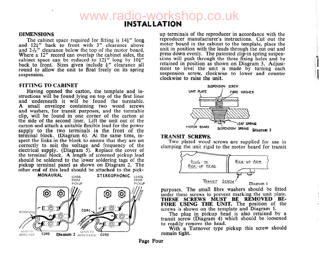
DIMENSIONS
The
cabinet space required for fitting
is
14t"
long
and.
12t"
back to front with
3"
clearance above
and 21\-" clearance below the top of the motor board.
Where a12" record can overlap the cabinet sides, the
cabinet space can be reduced to
12-!-"
long by
lOt"
back to front. Sizes given include
i"
clearance all
round to allow the unit to float freely on its spring
suspension.
up terminals
of
the reproducer in accordance with the
reproducer manufacturer's instructions.
Cut
out the
motor
board
in the cabinet to the template, place the
unit in position with the leads through the cut out and
press down evenly.
The
patented clip-in spring suspen-
sions will push through the three fixing holes and
be
retained in position as shown on Diagram
3.
Adjust-
ment to level the unit
is
made by turning each
suspension screw, clockwise to lower and counter
clockwise to raise the unit.
I
\1
'\
TRANSIT
SCREWS.
Two plated wood screws are supplied for use in
clamping the unit rigid to the motor board for transit
ADM
~'!.t!.
P'C!<'l,!P
~
Diagram
4
purposes.
The
small fibre washers should be fitted
under these screws to prevent marking the unit plate.
THESE
SCREWS
MUST
BE
REMOVED
BE-
FORE
USING
THE
UNIT.
The
position
of
the
screws is shown on the template
and
Diagram
1.
The
plug in pickup head
is
also retained by a
transit screw (Diagram 4) which should be loosened
to readily remove the head.
With a
Turnover
type pickup this screw should
remain tight.
Four
CORE
Pai
e
FITTING
TO
CABINET
Having opened the carton, the template
and
in-
structions will be found lying
on
top
of
the first liner
and underneath it will be found the turntable.
Asmall envelope containing two wood screws
and
washers, for transit purposes, and the turntable
clip, will be found in one corner of the carton
at
the side
of
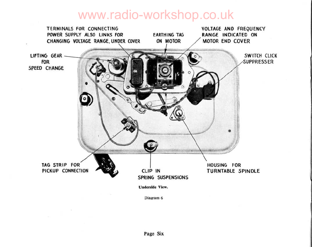
the second liner. Lift the unit out of the
carton and attach asuitable flexible lead for the power
supply to the two terminals in the front of the
terminal block. (Diagram 6).
At
the same time, in-
spect the links in the block to ensure that they are set
correctly to suit the voltage and frequency of the
electrical supply. (Diagram 5). Replace the cover of
the terminal block. Alength
of
screened pickup lead
should be soldered to the lower soldering tags of the
pickup terminal panel as shown on Diagram
2.
The
other end
of
this lead should be attached to the pick-
MONAURAL
,<m
STEREOPHONIC
LEADS
FROM
PICKUP