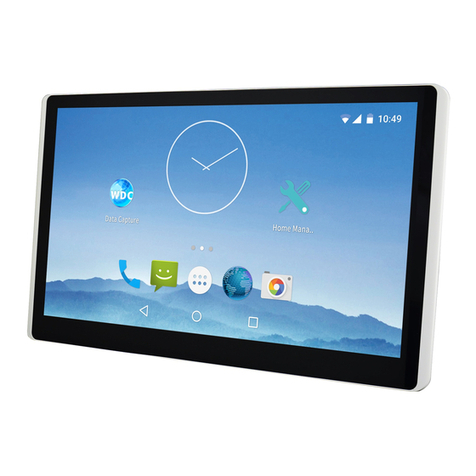
Garz Fricke SANVITO 10.1 WM V2.1 User manual

WE MAKE IT YOURS
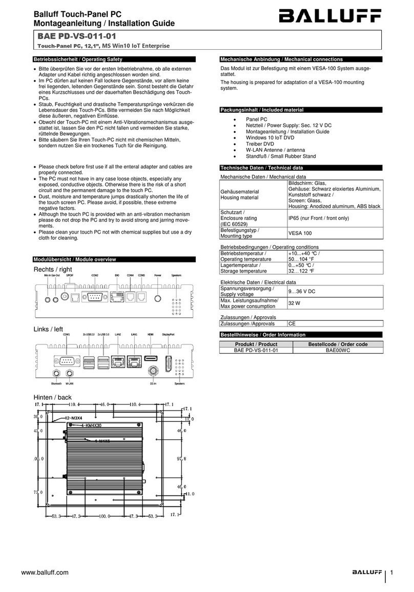
SANVITO 10.1 WM V2.1
ARM Cortex A9
Product Manual

Revision Date Author Description
V 1.0 29.01.2020 CG Initial document release for PCB revision V2.1
2
PRODUCT MANUAL
SANVITO
Document Revision History
The information in this document is subject to change without prior notice in order to improve reliability, design
and function and does not represent a commitment on the part of the manufacturer.
Online support on www.garz-fricke.com

PRODUCT MANUAL
SANVITO
Table of Contents
1. Introduction ....................................................................................... 4
2. Safety Hints........................................................................................ 5
3. Product Introduction ......................................................................... 6
3.1 Serial number..........................................................................................6
3.2 Related Documents and Online Support.................................................7
4. Technical Data.................................................................................... 8
4.1 Block Diagram SBC.................................................................................9
4.2 Connectors ..............................................................................................10
5. External Interfaces ACC MT ............................................................... 11
5.1 DC Power Supply .....................................................................................11
5.2 RS485.......................................................................................................11
5.3 Digital In/Out............................................................................................12
5.4 Ethernet 1 ................................................................................................12
5.5 USB Host..................................................................................................13
5.6 USB OTG ..................................................................................................13
5.7 Micro SD card holder...............................................................................14
5.8 Expansion Board Connector PCIe ...........................................................15
5.9 Figure Mainboard ...................................................................................16
6. Wall Installation Instructions............................................................. 17
6.1 On-Wall Cable Mounting with Cable Inlet ...............................................17
6.2 Wall Installation.......................................................................................18
Annex A: Technical Drawing.............................................................................. 20
Annex B: Quality and Incoming Inspections ...................................................... 21
B-1 Display and Touch....................................................................................21
Annex C: Hardware Revision Information ......................................................... 22
Annex D: Guidelines and Standards .................................................................. 23
D-1 RoHS Declaration ....................................................................................23
D-2 Supplier Declaration – Directive EG 1907/2006 REACH .........................23
D-3 UL Certification........................................................................................23
D-4 Garz & Fricke Conformity Statement......................................................23
Annex E: Technical Support ............................................................................. 24
Annex F: General Information .......................................................................... 25
* alternative assembly upon request

4
PRODUCT MANUAL
SANVITO
1. Introduction
Thank you very much for purchasing a Garz & Fricke product. Our products are dedicated to professional use
and therefore we suppose extended technical knowledge and practice in working with such products.
The information in this manual is subject to technical changes, particularly as a result of
continuous product upgrades. Thus this manual only reflects the technical status of the
products at the time of printing. Before design-in the device into your or your customer’s
product, please verify that this document and the therein described specification is the latest
revision and matches to the PCB version. We highly recommend contacting our technical sales
team prior to any activity of that kind.
Please also verify all herein described specifiations carefully before transfering them to your
own documentation for the end-product to ensure their validity for your installation conditions.
The attached documentation does not entail any guarantee on the part of Garz & Fricke GmbH
with respect to technical processes described in the manual or any product characteristics set
out in the manual. We do not accept any liability for any printing errors or other inaccuracies in
the manual unless it can be proven that we are aware of such errors or inaccuracies or that we
are unaware of these as a result of gross negligence and
Garz & Fricke has failed to eliminate these errors or inaccuracies for this reason.
Garz & Fricke GmbH expressly informs that this manual only contains a general description of
technical processes and instructions which may not be applicable in every individual case. In
cases of doubt, please contact our technical sales team.
In no event, Garz & Fricke is liable for any direct, indirect, special, incidental or consequential
damages arising out of use or resulting from non-compliancy of therein conditions and
precautions, even if advised of the possibility of such damages.
Distribution of this document to third parties is prohibited.
Before using a device covered by this document, please carefully read the applied master
supply agreement.
Embedded systems are complex and sensitive electronic products. Please act carefully and
ensure that only qualified personnel will handle and use the device at the stage of development.
In the event of damage to the device caused by failure to observe the hints in this manual
and on the device (especially the safety instructions), Garz & Fricke shall not be required to
honour the warranty even during the warranty period and shall be exempted from the statutory
accident liability obligation. Attempting to repair or modify the product also voids all warranty
claims.

5
PRODUCT MANUAL
SANVITO
2. Safety Hints
Please read this section carefully and observe the instructions for your own safety and correct use of the device.
Observe the warnings and instructions on the device and in the manual. Garz & Fricke embedded systems have
been built and tested by us and left the company in a perfectly safe condition.In order to maintain this condition
and ensure safe operation, the user must observe the instructions and warnings contained in this manual.
I. General Handling
Don’t drop or strike the unit: The PCB, display and/or other parts might be damaged.
Keep away from water and other liquids, the unit is not protected against.
Operate the unit under electrical and environmental conditions according to the technical
specification.
The electrical installations in the room must correspond to the requirements of the local
(country-specific) regulations.
Take care that there are no cables, particularly power cables, in areas where persons can trip
over them.
Do not place the device in direct sunlight, near heat sources or in a damp place.
All plugs on the connection cables must be screwed or locked to the housing.
Repairs may only be carried out by qualified specialist personnel authorized by
Garz & Fricke GmbH or their local distributors.
Maintenance or repair on the open device may only be carried out by qualified personnel
authorized by Garz & Fricke GmbH which is aware of with the associated dangers.
II. Electricity
The embedded systems may only be opened in accordance with the description in this user’s
manual for
- replacing of the (rechargeable, where applicable) lithium battery and/or
- configuration of interfaces, where applicable
These procedures have to be carried-out only by qualified specialist personnel.
When accessing internal components the device must be switched off and disconnected from
the power source.
When purchased core or basic versions without protecting back cover, don’t touch the PCB
directly with your fingers. Especially these products need to be handled very carefully.
Don’t operate or handle the unit without typical ESD protection measures, such as ground
earthing.
Operate the unit according to the technical specification only.
III. Damage or Permanent Malfunction
It must be assumed that a safe operation is no longer possible, in case
-the device has visible damage or
-the display is dark or shows strange pattern for longer period
-the device doesn’t react after a reset
In these cases the device must be shut down and secured against further use

6
&
SANVITO x2 10.1 WM IPS V1.2
900- 3891R
1.25 A 24 V
0º C T 40º C
Garz & Fricke GmbH
Schlachthofstrasse 20
21079 Hamburg
Made in Germany
PRODUCT MANUAL
SANVITO
3. Product Introduction
The "SANVITO 10.1 WM V2.1" is a control and operating unit for various applications.
3.1 Serial number
For service and later identification of the device a label containing the serial number and its QR-code is
located on the Device.
Serial Number

Flash-N-Go
http://mx31.de/b
Contains information about the usage of the G&F Flash-N-Go solution
which consists of three submodules:
Flash-N-Go Boot (A tiny boot loader)
Flash-N-Go System (A maintenance os)
Flash-N-Go Update (A GUI based update solution for all os)
Linux Yocto Jethro
http://mx31.de/9
Contains information about Linux BSP with
development environment Linux Embedded System Yocto (Codename:
Jethro, Version 3.0) includes first information about the bootloader
Flash-N-Go
7
PRODUCT MANUAL
SANVITO
3.2 Related Documents and Online Support
This document contains operating system specific information. The following additional documentations are
available:
OPERATING SYSTEMS
UPDATE / BOOT / SYSTEM

8
PRODUCT MANUAL
SANVITO
4. Technical Data
Type x2l
CPU Type
i.MX6 Dual
Core Class
ARM Cortex - A9
Core Clock
1 GHz
Features
NEON for SIMD media acceleration and VFP operations; Multi-format HD 1080p video de-coder and HD
720p video encoder hardware engine.
1 MB L2 cache
GPU
Vivante GC 2000+ (4 shaders)
Vivante GC 355
Vivante GC 320, 2 Layer composition
HW Accelerators
OpenGL ES 1.1/ 2.0/ 3.0 & Haiti,
OpenGL 1.1 EP,
Open GL 1.1
RTC
Accuracy: +/- 30 ppm at 25°C
Memory
eMMC Flash
4 GB PSLC MMC Flash (8 GB in MLC Mode)
RAM Standard
1GB 64 bit DDR3L
SD Card Slot
4 bit MMC/SDIO/SD/SDHC
Operating Systems
Supported OS
Linux Yocto, Android
Communication Interfaces
Network
1x 10/100 Mbit/s Ethernet (RJ-45)
USB
1x 480 Mbit/s Host (Type A)
RS-485
1x RS-485 galvanic isolated
Miscellaneous
Sensors
Ambient Light Sensor
LED
2 colour status LEDs
Audio
Audio Internal
2x Speaker 1.0 W; RMS (8 Ω)
Micro Internal
Display and Touch
Size
10.1 inch/ 255.85 mm
Resolution
1280 x 800 pixel
Brightness
Typ. 420 cd/ m
Backlight Lifetime
Min. 50 000 h
Viewing Angle
85°, 85°, 85°, 85° (UDRL)
Color
24 bit (16.7 Mio. colors)
Touch
projected capacitive single touch
Housing
Front
3.0mm thoughened glass, RAL 9005, optical bonded with touch and display
Frame
Fine zinc alloy, matt chrome
Rear
ABS-PC/ 1.4016 stainless steel
Ingress Protection
IP30
Device Dimensions
W x H x D
271.4 x 188.2 x 41.7 mm
Weight
1939 g
Power Supply
Supply Voltage
Nom. 24 V DC or PoE+ (802.3at)
Consumption
Typ. 10.2 W; max.25.5 W
Typical Environmental Conditions
Storage Temperature
-20 to +70°C
Operating Temperature
0 to +60°C
Humidity
5 to 90% RH
Expansion Cards
Extension Card
tbd.

9
PRODUCT MANUAL
SANVITO
4.1 Block Diagram SBC
Tbd.

Pos. Description
1DC Power Supply
2Ethernet
3Factory Reset
4Digital In/Out
5 RS 485
6Expansion Boar Connector PCIe
7Micro SD card holder
8USB OTG
9USB Host
10 Reset
10
PRODUCT MANUAL
SANVITO
4.2 Connectors
As this manual describes a core version, the internal and external interfaces will be mentioned in the following
chapter.
1
6
87
2
10
9
3
4
5

Pin Name Description Level
1DCIN Plus 24V
2GND Minus
Pin Name Description
1RS485#1_A RS485 Port 1
2RS485#1_B RS485 Port 1
3RS485#1_GND Ground Port 1
11
PRODUCT MANUAL
SANVITO
5.1 DC Power Supply
5.2 RS485
5. External Interfaces ACC MT
1
1

Pin Name Description
1DOUT1A Digital Out Dry-Contact 1
2DOUT1B Digital Out Dry-Contact 1
3DOUT2A Digital Out Dry-Contact 2
4DOUT2B Digital Out Dry-Contact 2
5DIN1+ Digital In 1 high side
6DIN1- Digital In 1 low side
7DIN2+ Digital In 2 high side
8DIN2- Digital In 2 low side
Pin Name Description
J1 TX+ Transmit data plus
J2 TX- Transmit data minus
J3 RX+ Receive data plus
J4 Spare1+ Spare 1+
J5 Spare1- Spare 1-
J6 RX- Receive data minus
J7 Spare2+ Spare 2+
J8 Spare2- Spare 2-
Sh Shield Schirm
12
1
1
PRODUCT MANUAL
SANVITO
5.3 Digital In/Out
5.4 Ethernet 1

5.5 USB Host
Pin Name Description Level
1VCC Power supply +5V 500mA
2D- Data minus
3D+ Data plus
4GND Ground
Sh Shield Schirm
Pin Name Description Level
1VCC Power supply +5V max 500mA
2D- Data minus
3D+ Data plus
4USB Device ID Device ID
5GND Ground
13
1
1
PRODUCT MANUAL
SANVITO
5.6 USB OTG

14
PRODUCT MANUAL
SANVITO
5.7 Micro SD card holder
Pin Name Description Level
1DAT3 Data +3,3V
2CMD Pullup +3,3V
3GND Ground 0V
4VDD Supply +3,3V
5CLK Clock +3,3V
6GND Ground 0V
7DAT0 Data +3,3V
8DAT1 Data +3,3V
9DAT2 Data +3,3V
10 CD Card detection +3,3V
11 WP Write protection +3,3V
12 COM Common ground 0V
Header: Micro SD card

Pin Name Description Level
1VCC1 Supply +5,0V
2VCC1 Supply +5,0V
3VCC1 Supply +5,0V
4VCC1 Supply +5,0V
5VCC1 Supply +5,0V
6VCC2 Supply +3,3V
7VCC2 Supply +3,3V
8VCC2 Supply +3,3V
9VCC2 Supply +3,3V
10 VCC2 Supply +3,3V
11 GND Ground
12 GND Ground
13 GND Ground
14 GND Ground
15 I2C2_SCL IIC SCL +3,3V
16 I2C2_SDA IIC SDA +3,3V
17 GND Ground
18 AN_IN_PWR CPU Signal for Supply Rail Analog IN +3,3V
19 AN_OUT_PWR CPU Signal for Supply Rail Analog OUT +3,3V
20 GND Ground
21 GPIO GPIO 3,3V
22 GPIO GPIO 3,3V
23 GND Ground
24 ETH1_RESET# CPU signal for Reset Ethernet 1 +3,3V
25 ETH2_RESET# CPU signal for Reset Ethernet 2 +3,3V
26 UART_RESET# CPU signal for Reset UART +3,3V
27 RS485_PWR1 CPU signal for supply rail RS485_1 +3,3V
28 RS485_PWR2 CPU signal for supply rail RS485_2 +3,3V
29 RS485_PWR3 CPU signal for supply rail RS485_3 +3,3V
30 RS485_PWR4 CPU signal for supply rail RS485_4 +3,3V
31 GND Ground
32 USB3DP USB 3 data plus +3,3V
33 USB3DM USB 3 data minus +3,3V
34 GND Ground
35 USB1DP USB 1 data plus +3,3V
36 USB1DM USB 1 data minus +3,3V
37 GND Ground
38 USB2DP USB 2 data plus +3,3V
39 USB2DM USB 2 data minus +3,3V
40 GND Ground
15
PRODUCT MANUAL
SANVITO
5.8 Expansion Board Connector PCIe

16
PRODUCT MANUAL
SANVITO
5.9 Figure Mainboard

17
PRODUCT MANUAL
SANVITO
6. Wall Installation Instructions
6.1 On-Wall Cable Mounting with Cable Inlet
If intended to use on-wall cable mounting make sure to replace the slide-in modules. Therefore remove the
pre-installed modules. Following install the cable-inlet-modules and fasten the two screws. The cables can be
stick trough the material.

18
PRODUCT MANUAL
SANVITO
6.2 Wall Installation
To install the wall holder use four screws with sufficient holding force. For a flushmounted cable installation
consider the position of the flush-mount box as shown in the following figure.
Flush-mount box
200
112
100
56
Aufputz-Montage
190
90
Unterputz-Montage
Possible screw positioning 1:
Possible screw positioning 2:

19
PRODUCT MANUAL
SANVITO
After installing the wall holder the device can be hook in.
Finally fix the device on the wall holder with a screw from the bottom side as shown in the figure.

Annex A: Technical Drawing
271,4
188,2
135,60 (AA)
216,96 (AA)
R6,60
(4x)
42 ±0,5
227,4
insert element for flush
mounting cables/
Einschubelement für
Unterputz-Kabel
cable entry element for
surfave mounting cables/
Kabeldurchführung
für Aufputz-Kabel
135,4
11
10
R2,50
R56
R105,1
200
190
112
90
R100
94,2
AA
A-A
01 02 03 04 05 06 07 08 09
Y (1 : 1)
14
15
X (1 : 1)
13
12
Fehlende Maße/Geometrien entnehmen Sie bitte dem CAD Datensatz/
missing dimensions according to 3D data
Depiction shows also optional equipment/
Darstellung zeigt auch optionale Ausstattung
Depiction without expansionboard,
Cover and wall mount /
Darstellung ohne Expansionboard,
Abdeckung und Wandhalterung
Modell beinhaltet noch alte Teile
die Kunststoffhaube
der Wandhalter
die Platinen
die Abdeckhaube für das Expansionboard
diese Zeichnungist nur fürs Manual erstellt worden
17.01.2020 Schc
Index
Bezeichnung/designation
01
Analog I/O
02
Ethernet 2
03
Ethernet 3
04
RS485 1
05
RS485 2-RS485 5
06
RS485 1
07
Digital I/O
08
Ethernet 1
09
DC Power Supply
10
USB Host
11
Reset Button
12
Factory Reset
13
Status LED
14
Factory Reset
15
Status LED
8 7
A
B
23456 1
578 246 13
E
D
C
F F
D
B
A
E
C
Redistribution and duplication of this document, recovery and
exploitationNotification of its contents is prohibited unless expressly
permitted. Infringements require compensation. All rights for the
case reserved for patent, utility model or design registration.
Schutzvermerk gemäss ISO 16016 /
refer to protection notice ISO 16016
Genehmigt /
appr.
Geprüft /
checked
Bearb. /
processed
Datum /
date
Name /
name
Einheit /
unit
: mm
© Garz & Fricke GmbH
kg
Gewicht /
weight
:
16.01.20
C. Schäfer
1
1
Blatt
page
900-xxxxR
1:2
Maßstab /
scale
:
Werkstoff /
material
:
-
00
Revision
Version
Benennung /
discribtion
:
PDM-ID:
Artikel-Nr. /
article no. :
www.garz-fricke.com
Schlachthofstraße 20
21079 Hamburg
entgraten und
scharfe Kanten
brechen /
Deburr
and break sharp
edges
Maße o. Toleranzangabe /
dimensions w/o tolerance
SANVITO 10.1 WM IPS (GuF)
SANVITO 10.1 WM IPS
(GuF Variante)
Table of contents
