Gas Sense GS-220.P User manual

Invest Electronics LTD
GS-220.P
GAS SENSOR
mount • settings • operation • maintenance
mount and exploitation manual (version 1.0/Octo er 2007)
Invest Electronics reserve the right for
changes in the document without notification

www.gassense.eu
Gas Sensor
GS-220.P
GS-220.P CONTENTS
1. Introduction .................................................................................................. 4
1.1. Safety instructions .................................................................................. 4
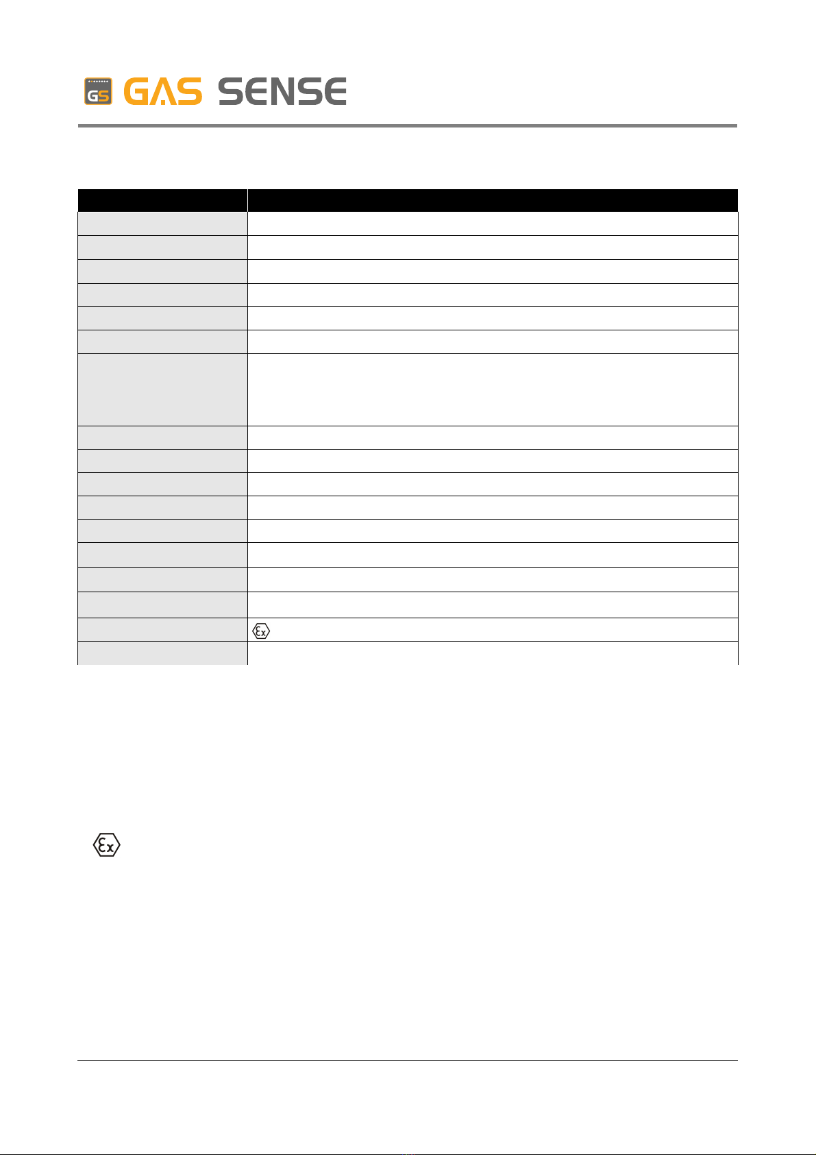
1.2. Specifications ......................................................................................... 5
1.3. Certificates and standards ..................................................................... 5
2. Product review ............................................................................................. 6
2.1. General review ....................................................................................... 6
2.2. Typical application .................................................................................. 7
2.3. Semiconductor gas sensing element .......................................................... 7
3. ount ............................................................................................................. 8
3.1. Introduction ............................................................................................ 8
3.2. Transportation and storage .................................................................... 8
3.3. Prior to mount ......................................................................................... 8
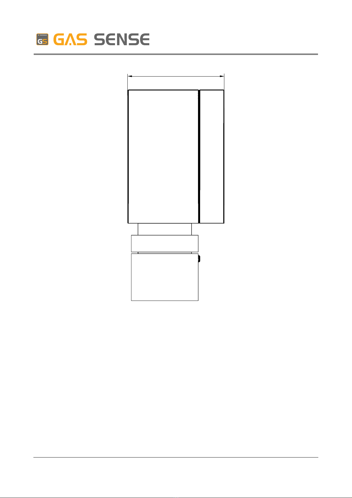
3.4. Dimensions ............................................................................................ 9
3.5. Mechanical installation ......................................................................... 10
3.6. Electrical installation ............................................................................. 12
4. Settings ....................................................................................................... 14
4.1. Introduction .......................................................................................... 14
4.2. Sensor cali ration ................................................................................ 14
5. Operation .................................................................................................... 16
5.1. Operation modes .................................................................................. 16
5.1.1. Warm up mode ............................................................................. 16
5.1.2. Normal operation mode ................................................................ 16
5.1.3. Danger mode ............................................................................... 17
5.1.4. Alarm mode .................................................................................. 17
5.1.5. Fault mode ................................................................................... 17
6. aintenance ............................................................................................... 19
6.1. Check and re-adjustment ..................................................................... 19
6.2. Diagnostics of frequent pro lems ........................................................ 19
ver.1.0 page 2 / 23

www.gassense.eu
Gas Sensor
GS-220.P
7. Customer support ...................................................................................... 20
7.1. Contact information .............................................................................. 20
7.2. Warranty ............................................................................................... 20
7.3. Order codification ................................................................................. 21
APPENDIX A – a reviations ........................................................................ 22
APPENDIX B – order codes .......................................................................... 23
ver.1.0 page 3 / 23

www.gassense.eu
Gas Sensor
GS-220.P
CHAPTER
1INTRODUCTION
1.1. Safety instructions
Before using the unit read carefully the manual. It consists important information,
regarding user safety and correct system exploitation.
Gas sensor must be mounted only by licensed personnel !
Electrical installation:
✔Electrical connections must e done only y licensed electrical installer.
✔Make sure that prior to connection, all electrical pins ARE NOT energized
✔All electrical connections must e done according to unit's normative
requirements
✔Prior to switching on the unit make sure that the voltage of the power supply
corresponds to manufacturer requirements.
Exploitation in potentially combustible environments:
✔The gas sensor is to e used only in working environments for which it has
certification.
✔In case of mechanical damages of the gas sensor's corpus, the unit ecomes
non-effective for exploitation in potentially com usti le environments.
✔For dismounting first switch off the power supply and after no less than 10
minutes start dismounting.
Warning: the gas sensor is designed for exploitation in potentially combustible
or toxic environment. The long lasting exposure to high concentrations may
lead to death.
ver.1.0 page 4 / 23

www.gassense.eu
Gas Sensor
GS-220.P
1.2. Specifications
Parameters Value
Dimensions 125х125х58mm
Electrical supply 12 ÷ 24 VDC
Power consumption max 2W
Controlled gases Com usti le and toxic (for full list ref. to APPENDIX B)
Signalization levels 2
Sensor element Semiconductor, catalytic or electrochemical
Sensor life expectancy Depends on sensor type:
•For electrochemical sensors - 12÷24 months
•For semi conductor and cathalytical – depends on the environment
pollution from 3 to 8 years
Indication LED
Outputs 2 digital (Danger and Alarm)
Ingress Protection IP65
Corpus material Aluminium
Weight 550 g
Operating temperature -20 ÷ 50°C
Humidity 30 ÷ 95 % RH (non condensing)
Pressure The atmosphere pressure ±10%
Explosion Proof II 2G EEx Ia IIC T5
Other Auto diagnostics
Ta le 1.1 – specifications
1.3. Certificates and standards
Gas sensor GS-220 is certified according to all requirements of Directive 94/9/EC
(ATEX) and has marking code
ver.1.0 page 5 / 23
II 2G EEx Ia IIC T5

www.gassense.eu
Gas Sensor
GS-220.P
CHAPTER
2PRODUCT REVIEW
2.1. General Review
GS-220 gas sensor is designed to detect and control com usti le and toxic gases in
the atmosphere. They are compati le with GA-220 series gas controllers and with other
devices with digital outputs. Its main specification are:
✔Detection and control for over 20 types of gases
✔Low power consumption (max 2W)
✔Digital outputs
✔Auto diagnostics
✔LED indication
✔Ingress protection IP65
✔ATEX certificate
Figure 2.1. – General view without lid
ver.1.0 page 6 / 23
Gas sensitive element
Ca le input
LED indication
Connection
Terminals

www.gassense.eu
Gas Sensor
GS-220.P
2.2. Typical application
Gas sensor GS-220 is offered in different variations, depending on gas sensor
element. It gives solutions for control of over 20 types of gases. Few of its typical
applications are:
✔underground parking garages
✔oiler premises
✔natural gas stations, petrol stations
✔manufactures with toxic gases emissions
✔la oratories
2.3. Semiconductor gas sensing element
Semiconductor layer heated to 400ºC. After hydrocar on gas fall on sensor, it's
conduction changes logarithmically to gas concentrations.
ver.1.0 page 7 / 23

www.gassense.eu
Gas Sensor
GS-220.P
CHAPTER
3OUNT
3.1. Introduction
Warning: gas controller must be mounted only by licensed technician, familiar
with this document or authorized by the manufacturer.
GS-220 is designed for mount via 2 olts situated cornerwise on the panel. It’s
connected to the gas controller y four core ca le.
3.2. Transportation and Storage
During transportation of gas sensor GS-220 specific measures for minimum vi ration
and shaking of the unit must e taken. The unit must e transported only in its original
packaging.
Gas sensor could e stored indoors with temperature from -20ºC to +70ºC and
humidity from 10% to 95%. The unit must not e exposed on direct sun light.
Warning: The life of the electrochemical gas sensors expires and their
sensitivity towards the gas decreases with time regardless the fact that they
may not be installed!
3.3. Prior to mount
Before mounting the unit, make sure that:
✔You are familiar with the safety instructions
✔You are familiar with the mount instructions (this manual)
✔You have all parts of the delivery. In case any of the parts is missing contact
your supplier or Invest Electronics Ltd., contacts are listed in Chapter 7, part 7.1.
✔You have all necessary tools
✔All connections are not energized during connection
ver.1.0 page 8 / 23

www.gassense.eu
Gas Sensor
GS-220.P
3.4. Dimensions
Gas sensor GS-220 is produced in aluminum corpus with ingress protection IP65.
Dimensions and installation openings on the corpus are shown on figure 3.1.
ote: all dimensions are in millimeters- mm
Figure 3.1. – Dimensions and mounting holes. Front view
ver.1.0 page 9 / 23
125
52
80
125
113

www.gassense.eu
Gas Sensor
GS-220.P
Figure 3.2 – Dimensions. Side view
3.5. echanical installation
Gas sensor GS-220 is attached via 2 olts φ3,8 х 35.
When attaching to wall keep the following steps for gas sensor attachment :
1. Drill openings into the wall according to fig. 3.1.
2. Place φ6 mm du els into the openings
3. Unpack the sensor
4. Take off sensor’s lid y removing four olts (fig. 3.3.)
ver.1.0 page 10 / 23
58

www.gassense.eu
Gas Sensor
GS-220.P
Figure 3.3 – Take off sensor’s lid
5. Screw olts (2 olts) into the du els on the wall
Figure 3.4 – wall mounting
6. Proceed to electrical mount.
ver.1.0 page 11 / 23

www.gassense.eu
Gas Sensor
GS-220.P
3.6. Electrical installation
Gas sensor GS-220 is connected to the gas controller or other executing device via
three or four core ca le.
The recommended connecting conductor’s sections according to line length are
shown in ta le 3.1.
Length Section
Up to 100m 4 x 0,5 mm2
Up to 200 m 4 x 0,75 mm2
From 200m to 300m 4 x 1 mm2
Ta le 3.1 – length and section of the connecting conductors
Figure 3.5. – electrical connecting - general view
Typical GS-220 connecting to GA-220 series gas controller is done via four core
ca le. For connecting follow the steps ellow:
1. Open the panel (unscrew four olts)
2. Place ca le through ca le input (figure 3.5.)
3. Connect to terminals on the right (when gas drill points downwards) - figure
3.5. Open terminal y pushing with screwdriver, place the conductor core into
opening and release.
ver.1.0 page 12 / 23
Ca le input
Connection
terminals

www.gassense.eu
Gas Sensor
GS-220.P
4. Connect corresponding terminals of gas controller and gas sensor: + ↔ +
1 ↔ 1 ; 2 ↔ 2 ; - ↔ - ;
Figure. 3.6. – connecting ca le to terminal
5. Close the panel and screw four olts
6. Gas sensor is ready for operation
ote: connecting could be done also via three core cable, when having two
signalization levels is not necessary (ex. Only 20% LEL). In this case output “1”
is not connected.
ver.1.0 page 13 / 23

www.gassense.eu
Gas Sensor
GS-220.P
CHAPTER
4SETTINGS
4.1. Introduction
This chapter descri es sensor adjustments. Testing and cali ration of sensors must
e done at least once every 6 months.
4.2. Calibration
Tools necessary for GS-220 gas sensor cali ration
✔test gas for danger level
✔test gas for alarm level
✔precise voltmeter, that could detect 0÷6 V DC range.
✔screwdriver – flat; max 3mm
✔special cali ration connector
ver.1.0 page 14 / 23
GND
ALARM
SENSE
DANGER
trimer 1
trimer 2
gas
Cali ration terminal

www.gassense.eu
Gas Sensor
GS-220.P
Steps for setting up GS-220 gas sensor
1) For sensors with semi conductor gas sensing element (ref. APPENDIX B) the
device needs to e previously warmed up for at least one hour.
2) Switch on voltmeter etween outputs GND and SENSE (1 and 4 ) of
cali ration terminal
3) Present test gas for DANGER level to gas sensing element with flow speed of
1l/min.
4) Measure pressure value, when voltmeter is sta le
5) Switch on voltmeter etween GND and DANGER outputs (1 and 3) of
cali ration terminal
6) Screw trimer 1, so voltmeter must show pressure value of 90% of the pressure
value measured during step 4
7) switch on voltmeter etween GND and SENSE outputs (1 and 4) of cali ration
terminal
8) present test gas for alarm level to gas sensing element with flow speed 1l/min.
9) measure pressure value , when voltmeter is sta le
10) Switch on voltmeter etween GND and ALARM outputs (1 and 2) of
cali ration terminal
11) Screw trimer 2, so voltmeter must show pressure value of 90% of the
pressure value measured during step 9
ver.1.0 page 15 / 23

www.gassense.eu
Gas Sensor
GS-220.P
CHAPTER
5OPERATION
5.1. Operating modes
This chapter shows operating modes of gas sensor GS-220, their activation, as well
as indications and output signals, which are generated in each one.
5.1.1. Warm up mode
This is the mode that starts right after the powering of the sensor. It is used for
sta ilizing measurements of the diagram as well as initial warming of the gas sensitive
element (gas sensitive element must e warm in order to measure right). In this mode gas
sensor does not measure current gas concentration.
Characteristics and output levels of warm up mode:
Characteristics Values
LED indication •DANGER – does not light
•ALARM – does not light
•FAULT – lights
Digital outputs •DANGER ( terminal ) – digital „0“
•ALARM ( terminal ) – digital „0“
Other Time: 70 seconds
Ta le 5.1. – characteristics of warm up mode
5.1.2. Normal operation mode
This is the mode where the measured gas concentration value is etween zero and
DANGER levels.
Characteristics and output levels of normal operation mode:
ver.1.0 page 16 / 23

www.gassense.eu
Gas Sensor
GS-220.P
Characteristics Values
LED indication •DANGER – does not light
•ALARM – does not light
•FAULT – does not light
Digital outputs •DANGER ( terminal ) – digital „0“
•ALARM ( terminal ) – digital „0“
Ta le 5.2. – characteristics of normal operation mode
5.1.3. Danger level mode
This is the mode where the measured gas concentration value is etween DANGER
and ALARM levels.
Characteristics and output levels of DANGER level mode:
Characteristics Values
LED indication •DANGER – lights
•ALARM – does not light
•FAULT – does not light
Digital outputs •DANGER ( terminal ) – digital „1“
•ALARM ( terminal ) – digital „0“
Ta le 5.3. – characteristics of danger mode
5.1.4. Alarm mode
This is the mode where the measured gas concentration value is a ove alarm level.
Characteristics and output levels of alarm level mode:
Characteristics Values
LED indication •DANGER – lights
•ALARM – lights
•FAULT – does not light
Digital outputs •DANGER ( terminal ) – digital „1“
•ALARM ( terminal ) – digital „1“
Ta le 5.4. – characteristics of alarm mode
5.1.5. Fault mode
This is the mode where a pro lem with gas sensitive element is detected
ver.1.0 page 17 / 23

www.gassense.eu
Gas Sensor
GS-220.P
Characteristics and output levels of fault mode:
Characteristics Values
LED indication •DANGER – does not light
•ALARM – does not light
•FAULT – lights
Digital outputs •DANGER ( terminal ) – digital „0“
•ALARM ( terminal ) – digital „0“
Ta le 5.5. – characteristics of fault mode
ver.1.0 page 18 / 23

www.gassense.eu
Gas Sensor
GS-220.P
CHAPTER
6AINTENANCE
6.1. Check and re-adjustment
Technically gas sensitive elements used in GS-220 sensor, have specific life time
period. And their gas sensitivity towards the gas decreases with time. Preventive
maintenance and/or re-adjustment at least once every six months must e held.
Cali ration and adjustment methods are given in chapter 4 - Settings.
6.2. Diagnostics and frequent problems
Symptom Problem Solution
Yellow LED indicator does not light
up after switching on the system
Power supply lost Check connecting ca les and
voltage
Gas sensor detects gas, LEDs
lights, ut gas controller does not
respond.
1. Wrong wiring
2. Defected Intrinsically safe line of
gas controller GA-220
1. Check connections
2. Change Intrinsically safe lines
(contact your dealer or
manufacturer)
Sensor is in DANGER mode, ut
gas controller GA-220 shows
sensor FAULT
Wrong wiring Change „1“ and „2” terminals
Sensor is in FAULT mode 1. Broken connection
2. Faulty gas sensor element
1. Check connection from gas
sensitive element to electronic
module
2. Change gas sensitive element
Ta le. 6.1 – frequent pro lems and their solutions
ver.1.0 page 19 / 23

www.gassense.eu
Gas Sensor
GS-220.P
CHAPTER
7CUSTU ER SUPPORT
7.1. Contact information
INVEST ELECTRONICS LTD.
145 Brezovsko shose street
Plovdiv 4003 Bulgaria
Tel. + 359-32-960143
Fax: + 359-32-960144
e-mail: [email protected]
we : http://www.gassense.eu
7.2. Warranty
✔Warranty period is 12 months, ut not more than 18 months from date of
warranty issuing
✔Warranty applies for defects, due to exploitation during the warranty period,
ecause of non quality materials or ad production. Such defects are managed free
of charge in the manufacturer production area.
✔The warranty is accepted only with correctly in clear hand writing warranty
document. The warranty must contain signatures of the vendor and vendee and the
date of purchasing.
Free of charge warranty maintenance could e refused in the following situations:
✔Discrepancy etween information in the document and the actual product or
when the serial num er marking is removed or switched.
✔The requirements for storage, mount or exploitation are not o eyed
✔For any repairs made y unauthorized individuals or when warranty sticker or
seal is damaged
✔Damages due to vi rations, mechanic faulties, hitting, or overloading on poor
management account.
✔Damages due to natural disasters – lightning, inundation, power stroke, fires
and other force majeure circumstances.
ver.1.0 page 20 / 23
Table of contents
Other Gas Sense Gas Detector manuals