manuals.online logo
Brands
  1. Home
  2. •
  3. Brands
  4. •
  5. ASI
  6. •
  7. Dispenser
  8. •
  9. ASI 0338 Installation instructions

ASI 0338 Installation instructions

Automatic Sensor Detection Range {inches (mm)}
Dispensing Volume/Weight {fl oz (ml) / oz (gm)}
Dimensions Spout (W x H x D) {inch (mm)}
Operation Mode
Sensing Delay Time (msec)
Room Temperature {°F (°C)}
Supply Reservoir Type {fl oz (ml)}
4-3/4 ± 1-1/2 (121 ± 38)
0.034 ~ 0.051 (1 ~ 1.5) / 0.33 ~ 0.4 (2.4 ~ 2.9)
1-15/16 x 4 x 5-9/16 (49.2 x 101.3 x 142)
Automatic from Sensor Trigger
500 ~ 1k
41 ~ 104 (5 ~ 40)
1. SPECIFICATIONS:
INSTALLATION & OPERATION INSTRUCTIONS
2. ITEM LIST:
Reusable, Replaceable 50.7 (1500)
Adapter Type Required 6 VDC from 120~240 VAC Plug-In Adapter Model No. 72-ACA
O
X
~
~
A
C
B
FOR MODEL 0338 TOP-FILL, Liquid SD №:
Soap Acidity-Alkalinity Range (pH)
Dimensions Pump (W x H x D) {inch (mm)}
Soap Viscosity {cP (mPa•s)}
5.5 ~ 8.5
4-5/8 x 12-1/4 x 5-1/16 (117.4 x 310.4 x 129.2)
1904011610 Pg 1 of 2
Rev A 2 August 2019
1-3000
Spout Material & Finish
Unit Net Wt (empty) & Shipping Wt {lb(kg)}
316 SS, Bright finish only
2.6 & 3.3 (1.17 & 1.49)
Description
Funnel key
Metal Inlay Finish Plate
Top cap
Sensor assembley
Spout Assembly
Sensor Lens
Air Venting tube
O-ring
Elbow connector
Nozzle Tip (w/o mesh outlet)
Soap tube
SUS ring
Rubber washer for Escutcheon
SUS washer
Housing Locking nut
Refill tube assembly
Control box assembly
Mounting Bracket
Refill tube rubber washer
Soap pump & tank assembley
AC Adapter (part# 72-ACA)
Paddle-Key
Socket wrench
Plastic Anchor
Mounting Screw
Foam Pad
Qty.
1
1
1
1
1
1
1
1
1
1
1
1
1
1
1
1
1
1
1
1
1
2
1
3
3
1
No.
1
2
3
4
5
6
7
8
9
10
11
12
13
14
15
16
17
18
19
20
21
22
23
24
25
26
1. Provide horizontal and flat, clean and smooth mounting surface for Spout Escutcheon. (Item 13, Rubber Washer,
under Spout Escutcheon)
2. Make sure there is enough room around spout to adjust position for final assembly and make sure there is
adequate space to place pump-control-tank module under vanity within reach of Sensor Assembly Cable and
Soap Supply Tube. See Fig. 2 in Section 5.
3. Ensure there are no obstructions in front of unit in sensor zone.
4. Check operation of unit while holding in place by hand BEFORE permanent installation.
3. BEFORE INSTALLATION (See also Installation Mounting Template 1902271650)
READ THIS INSTRUCTION SHEET COMPLETELY BEFORE STARTING INSTALL
and RETAIN for future reference:
4. RECOMMENDED INSTALLATION, SPOUT:
RIM HEIGHT MAX 1-3/16" (30)
DISTANCE = 9-3/4" (248) MAX X;Y
Use "Touch Mark" on Template
(MT p/n 1902271650) and see
Section 5 INSTALLATION STEPS
Z is 4-5/8" (117.5) Please ensure
the nozzle of the soap dispenser
is within the washbasin.
1. Drill a 1-1/2" Dia. (Ø38) hole in the counter top after checking for appropriate clearances under the vanity (see Fig. 1 and Fig. 2).
2. Put the soap dispenser with rubber washer (item 13) through the hole in the Counter Top (Fig. 2). Place the SUS washer (items 14)
on the thread on the shaft under the vanity. Use the Screw Nut (Item 15) to fasten the soap dispenser to the washbasin.
3. Tape the installation mounting template (1902271650) at the appropriate location on the mounting surface.
4. Put the mounting template in the best installation position on the wall according to the test fit with tubes and cables (Fig. 2).
Do not tilt the unit during installation. Drill two (2) 1/4" Dia. (Ø6.4) holes at marked locations on mounting template.
5. Insert two (2) plastic anchors (supplied) into drilled holes (Fig. 3); remove template.
6. Insert two (2) screws (supplied) into plastic anchors and leave 3/16" (4.8) space from the wall under head (Fig. 3 & Fig. 4) for
hanging dispenser.
7. Hang the dispenser on the two (2) screws through the keyhole slots at backplate top. Tighten both screws (Fig. 5)
8. Connect the sensor wire (A), the soap tube (B), and the venting tube (C). (Fig. 6)
9. Connect the corrugated soap tube to the bottom of the dispenser shank. Ensure to thread in completely. (Fig. 7)
10. Connect the bottom coupler of the corrugated soap tube to the tank fill port. Ensure the rubber washer inside the coupler fitting
stays in place. (Fig. 8)
11. Connect the AC adapter pack to complete installation (Fig. 9). The LED will flash to signal low soap level as the default setting
after installation. Refer to Page 2 of this OM, Section 6, Fig’s 10 through 12 to fill soap.
5. INSTALLATION STEPS, Pump-Control-Tank Module
(Fig. 1) (Fig. 2)
1-1/2"(38)
(Fig. 3)
1/4 ( 6.4)"Ø
Item 24
COUNTER TOP
1-13/16"
(46.3) Install the spout with the sensor facing
forward, (Fig. 1) and/or ensure there is
no interference in the path of the sensor.
When installing the spout near a sensor
activated faucet, ensure the path of the
sensor on each unit does not intersect
each other (Fig. 2).
Fig. 1 Fig. 2
Ensure the soap tube can touch
the Mounting template to find the
best position for installation.
X
X
(Fig. 4)
3/16 (4.8)"
(Fig. 5) (Fig. 6) (Fig. 7)
There is a rubber washer inside.
(Fig. 8) (Fig. 9)
11
18
17
21
9
12
13
14
15
10
5
6
1
16
20
19
8
22
2
3
4
7
24 25
23
Y
X
Z
~
~
RIM HEIGHT
WASHBASIN
Intrusion Protection IPX4 - Sensor fully protected from water.
Rubber Washer
Item 13 under Escutcheon
Washer SUS
ltem 14
Locking Nut
ltem 15
Tool, Socket Wrench
ltem 23
26
Figures are best viewed
online for enhanced clarity
Escutcheon
BERLS.COM (704) 937-2673 129 Oakpark Drive, Unit A, Mooresville, NC 28115
COMMERCIAL
SUPPLY
7. PERIODICALLY CLEAN THE TANK
(Every 10 soap refills or 6 months, whichever is sooner)
1. Disconnect the power supply.
2. Disconnect the corrugated soap tube (A), the air-venting tube (B), the soap tube (C),
and the two soap level sensors (D & E). (A,B,C,D,E. Fig. 1 below, right)
Retain the rubber washer inside of the corrugated soap tube.
Remove tank from mounting bracket.
3. Fill the soap tank with water and shake it lightly.
Manually press the soap pump a few times
(full strokes, 3~8 times) to allow water to rinse
through and clean the soap pump.
4. Reinstall the corrugated soap tube
(with rubber washer {item 19} reinstalled
into coupler), the venting tube,
the soap tube, and the two soap level
sensors disconnected in step 2 above.
(A,B,C,D,E. Fig. 1 below, right).
Reinstall the soap tank into
the mounting bracket.
5. Reconnect the AC Adapter plug into the socket.
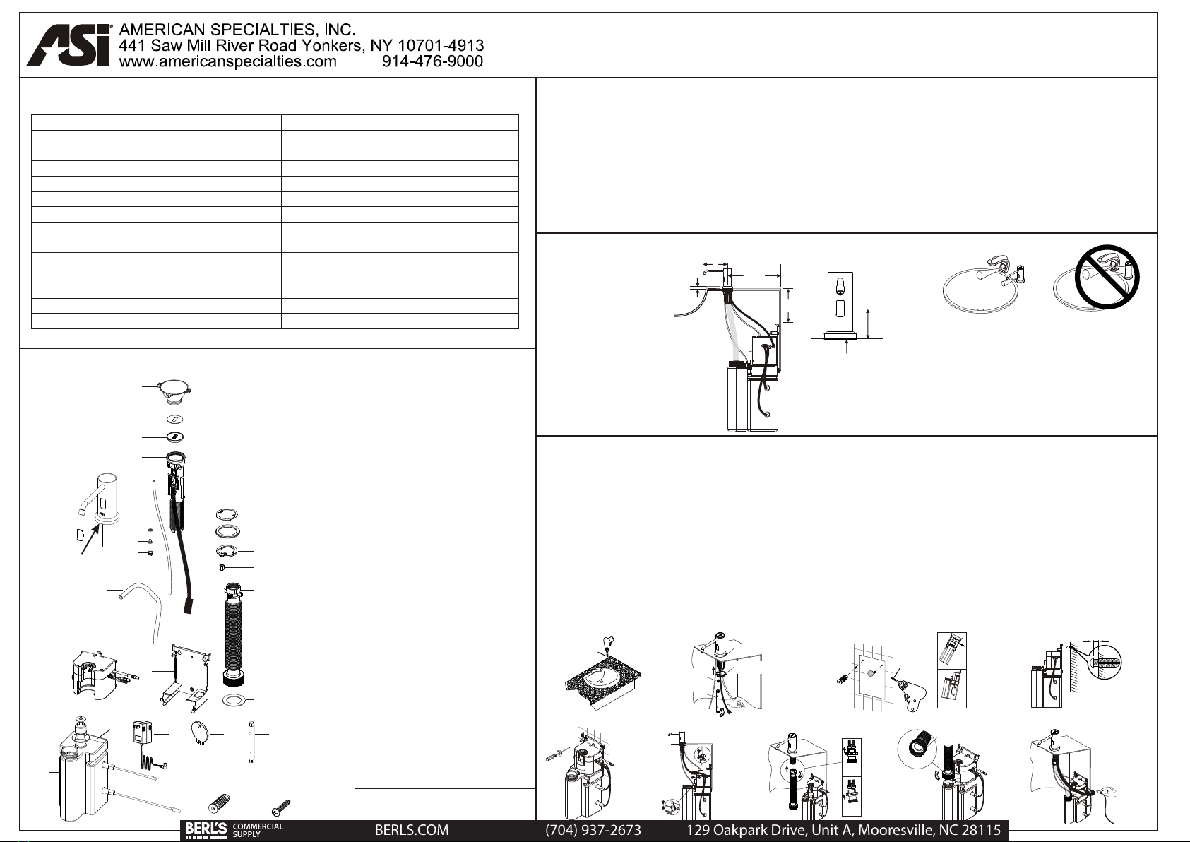
8. SENSING RANGE
Sensing is automatically controlled to set the appropriate distance for the triggering zone. This is based upon
mounting height above the counter and the ambient and reflected lighting conditions. There are no user adjustable
controls for this feature. It is important to observe the guidelines in Section 4 (on reverse side of these instructions)
and install unit to avoid false or inadvertent triggering from near-field obstructions and environmental conditions.
Orientation of spout to avoid “seeing” faucet running water and the arm or shirt cuff of a user will provide a more
satisfactory experience for the user.
10. CLEANING AND MAINTENANCE
DO NOT use steel wool or cleansing agents containing alcohol, acid, abrasives, or the like. Use of any cleaning or
maintenance products containing these substances could damage the finish of the soap dispenser. For surface
cleaning, use ONLY mild soap and water on a wet cloth, then wipe dry with a clean cloth or towel. When cleaning
bathroom tiles or counters, protect the soap dispenser from any splattering of harsh cleansers.
11.TROUBLESHOOTING
Problem Symptom
Unit activates, but no soap is
dispensed
Low volume soap dispensed
Solution Diagnostic
Check soap qualities, properties and level in reservoir.
Check spout nozzle, soap supply tube, and valve pump for clogs.
Soap leaks at bottom of housing Check if valve pump is not properly seated on connector neck
of reservoir or reservoir is damaged/punctured or top plate
connector or soap tube is damaged or not connected properly,
or valve pump body is damaged.
Unit does not respond at all or has
delayed response
Check all connections.
Clean any dirt/smudges from sensor.
Remove any obstructions near or in front of sensor.
If using AC adapter, make sure it is plugged into outlet completely
and that adapter is supplying correct power (see sections 1,5).
LED indicator blinking green Refill soap.
Green LED indicator stays on The wrong type of soap may have been used or the soap may
have thickened and congealed after long periods of inactivity.
Change to the right soap type or clean the soap tank and add
new soap to return to normal function.
No over-fill auditory warning
during soap refilling
Check all connections.
T
The soap level sensor may be damaged. Change the
soap tank assembly (item 20).
he control box may be damaged. Change the pump-motor-control
box (item 17).
1. Ensure no bright light source is aimed or reflected at the sensor.
2. Use fresh new liquid soap only and clean the soap container properly before each re-fill. Deposits of old
soap will lead to malfunction and jamming.
3. Do not dilute liquid soap unless concentrate. DO NOT use soap containing abrasive. Observe indicated
viscosity factor of liquid soap.
4. Do not immerse the soap dispenser in water or clean it under running water. This will lead to short circuit.
5. Should the dispenser be out of order do not attempt any repair work. Call your dealer for professional assistance.
9. IMPORTANT NOTICE
Remove soap tank and wash out spout nozzle and valve pump
and replace with fresh new soap.
6. OPERATION INSTRUCTIONS
A. Filling Soap
1. Open the fill port cap with the funnel-key or the provided paddle-key. (Fig. 10)
2. Thread in the funnel-key to the fill port to fill soap. (Fig. 11)
3.
4. Replace the cap after soap filling and use the funnel-key or paddle-key to tighten. (Fig. 12)
5.
When the soap level is filled a buzzer will sound. Stop refilling when the
warning is heard. Do not overfill. The auditory warning will last for 20 seconds during
which time the sensor will be turned off to prevent unwanted activation.
Place hands in front of the sensor to prime the system. The soap dispenser will activate up
to 10 times or until hands are removed to finish priming.
Note:Soap dispenser will automatically dispense once every 48 hours of inactivity to prevent
clogging in the soap tube and at the nozzle.
(Fig. 10) (Fig. 11) (Fig. 12)
(Fig. 1)
B. User's Instructions
1. Place hand below the dispenser spout within the sensing range. The dispenser will
automatically release the preset amount of liquid soap from the nozzle spout.
2. Obtain additional soap by withdrawing hand and then again placing hand below the
dispenser spout within the sensing range.
Rev A 2 August 2019
A
B
C
D
E
~
~
( )
REF
WASHBASIN
1904011610 Pg 2 of 2
BERLS.COM (704) 937-2673 129 Oakpark Drive, Unit A, Mooresville, NC 28115
COMMERCIAL
SUPPLY

Other ASI Dispenser manuals

ASI EZFILL 0394 Series Product manual

ASI

ASI EZFILL 0394 Series Product manual

ASI 0390 Product manual

ASI

ASI 0390 Product manual

ASI FS-0700 User manual

ASI

ASI FS-0700 User manual

ASI EZFILL 0390-1A Product manual

ASI

ASI EZFILL 0390-1A Product manual

ASI EZ FIL 0390-(n) User manual

ASI

ASI EZ FIL 0390-(n) User manual

ASI EZ FILL Product manual

ASI

ASI EZ FILL Product manual

ASI 0363 User manual

ASI

ASI 0363 User manual

ASI 8374 User manual

ASI

ASI 8374 User manual

ASI EZFILL 0391 Series Product manual

ASI

ASI EZFILL 0391 Series Product manual

ASI 0388 User manual

ASI

ASI 0388 User manual

ASI EZFILL 0393 Series User manual

ASI

ASI EZFILL 0393 Series User manual

ASI EZ FILL Operating manual

ASI

ASI EZ FILL Operating manual

ASI EZ-Fill 10-0390 Configuration guide

ASI

ASI EZ-Fill 10-0390 Configuration guide

ASI FS-0500 User manual

ASI

ASI FS-0500 User manual

Popular Dispenser manuals by other brands

Sealey MK66.V3 instructions

Sealey

Sealey MK66.V3 instructions

U-Line H-2274 manual

U-Line

U-Line H-2274 manual

diluo K1500186-040 user manual

diluo

diluo K1500186-040 user manual

Vortice PREMIUM S Instruction booklet

Vortice

Vortice PREMIUM S Instruction booklet

dosatron D9 Green Line user manual

dosatron

dosatron D9 Green Line user manual

Nordson Asymtek M-2000 Maintenance Training

Nordson

Nordson Asymtek M-2000 Maintenance Training

Zone UME user manual

Zone

Zone UME user manual

Schülke touchless D1 installation guide

Schülke

Schülke touchless D1 installation guide

Parker SciLog LabTec Series Installation, Operation & Maintenance Instruction Manual

Parker

Parker SciLog LabTec Series Installation, Operation & Maintenance Instruction Manual

UFESA Hygienic DM35 instruction manual

UFESA

UFESA Hygienic DM35 instruction manual

corob D180 user manual

corob

corob D180 user manual

Displays2go SMSDWDK Assembly instructions

Displays2go

Displays2go SMSDWDK Assembly instructions

Bravetti APD803B owner's manual

Bravetti

Bravetti APD803B owner's manual

ViscoTec preeflow eco-DUOMIX450 Operation & maintenance manual

ViscoTec

ViscoTec preeflow eco-DUOMIX450 Operation & maintenance manual

Oprema Juice Premix-Postmix Installation & Service Booklet

Oprema

Oprema Juice Premix-Postmix Installation & Service Booklet

PRISMAN Vario Touchless Instructions for assembly and operation

PRISMAN

PRISMAN Vario Touchless Instructions for assembly and operation

Tork 572028A Service manual

Tork

Tork 572028A Service manual

Nordson ProBlue Fulfill Customer product manual

Nordson

Nordson ProBlue Fulfill Customer product manual

manuals.online logo
manuals.online logoBrands
  • About & Mission
  • Contact us
  • Privacy Policy
  • Terms and Conditions

Copyright 2025 Manuals.Online. All Rights Reserved.