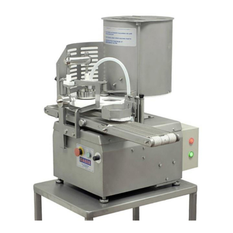
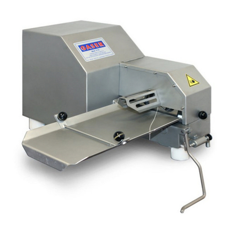
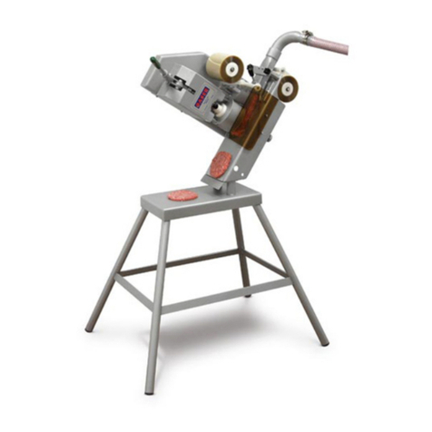
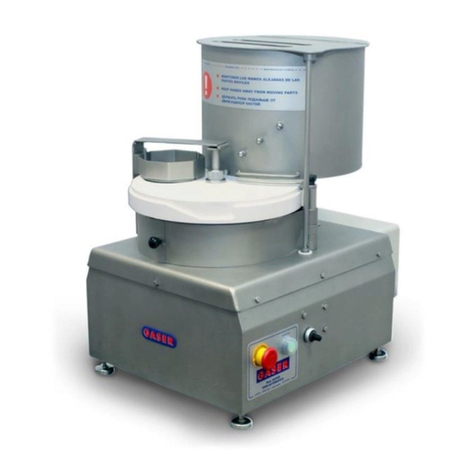
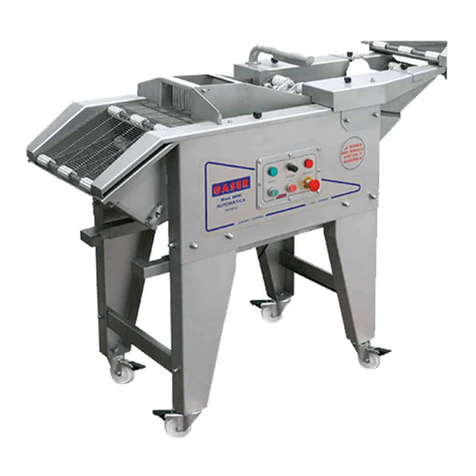
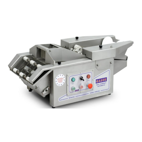
GASER V3000-CP User manual

AUTOMATIC HAMBURGER FORMING
MACHINE
Mod. V3000-CP

-2-
INDEX
1. INDUSTRIAS GASER............................................................................................4
2. EC DECLARATION OF CONFORMITY .................................................................5
3. HYGIENE CERTIFICATE.......................................................................................6
4. INTRODUCTION....................................................................................................7
4.1 Safety...............................................................................................................7
4.2 Hygiene............................................................................................................7
5. TECHNICAL SPECIFICATIONS.............................................................................8
6. RECEIPT AND START-UP.....................................................................................9
6.1 Receipt.............................................................................................................9
6.2 Start-up ............................................................................................................9
6.3 Operation.......................................................................................................11
6.3.1 Front control panel..............................................................................11
6.3.2 Rear control panel...............................................................................12
6.4 Notes .............................................................................................................12
7. CLEANING...........................................................................................................14
8. MAINTENANCE...................................................................................................17
9. TROUBLESHOOTING .........................................................................................18
10. GENERAL DIAGRAM.........................................................................................20
10.1 General overview ........................................................................................20
10.2 Meat entry overview.....................................................................................26
10.3 Interior belt overview....................................................................................27
10.3.1 Outlet system bearing housing overview...........................................28
10.3.2 Outlet system drive train overview ....................................................29
10.3.3 Outlet system passive roller overview...............................................30
10.4 Paper cutter overview...................................................................................31
10.4.1 V3000 Cutting blade overview ..........................................................32
10.5 Rubber rollers overview................................................................................33
10.6 Bellows overview..........................................................................................34
10.7 Connecting rod overview..............................................................................35
10.7.1 Complete connecting rod overview ...................................................36
10.7.2 Anti-rotation bearing overview...........................................................37

-3-
10.8 Paper ejector overview.................................................................................38
10.9 Former overview ..........................................................................................39
10.10 Electrical installation overview....................................................................40
10.10.1 Electrical cabinet overview..............................................................42
10.11 Pneumatic installation overview..................................................................43
10.11.1 Quick exhaust overview ..................................................................44
10.12 Stacker overview (optional) ........................................................................45
10.12.1 Stacker paddle overview .................................................................46
10.12. Conveyor belt overview.....................................................................47
12. PNEUMATIC DIAGRAMS ..................................................................................48
11. WIRING DIAGRAMS..........................................................................................50
11.1 Hamburger forming machine-Continuous filler connection............................50
11.2 PLC inputs and outputs ................................................................................51

-4-
1. INDUSTRIAS GASER
Since its foundation in 1969, INDUSTRIAS GASER has specialised in manufacturing a range of
stainless-steel machinery for the meat industry.
Since 1985 we have constantly developed technology for GASER-brand hamburger-forming
machines, developing a distinctive system based on a SIMPLER, MORE EFFECTIVE AND MORE
ECONOMICAL TECHNIQUE.
In the 1990s, INDUSTRIAS GASER expanded into markets in various countries around the world, and
not just in the hamburger sector.
We are aware that our work would be of no value without the trust of our existing clients and partners
or the interest shown by those who wish to join them.
We thank them all.
INDUSTRIAS GASER GASER EUROPA
Salt, Girona, SPAIN L’viv, UKRAINE
INDUSTRIAS GASER Ctra, Bescanó, 15, Pol. Torre Mirona 17190 Salt (Girona) - Spain
Tel. 34 972 23 65 72 | Fax 34 972 23 63 66 | Whatsapp: (34) 679 49 65 06
email: gaser@gaser.com
GASER EUROPA вул.Б.Лепкого,1 81160 смт.Щирець Пустомитівский р-н Львівська область
Украіна - Ukraine
Tel. 38 (03230) 67251/84
Fax 38 (03230) 67191
email: gasereuropa@gaser.com
For more information about the company and its products: www.gaser.com

-5-
2. EC DECLARATION OF CONFORMITY
We declare under our responsibility that the following machine:
Brand: GASER
Model: V3000-CP
Serial no.
Year of construction:
is in conformity with the following regulations
UNE-EN ISO 12100:2012
UNE-EN ISO 14120:2016
UNE-EN ISO 14121-1:2008
UNE-EN 60204-1:2007 60204-1:2007 CORR. 2010 60204-1:2007/A1:2009
UNE-EN ISO 13849-1:2008/AC:2009
and is in conformity with the following directives
Machinery directive: 2006/42/CE
Low voltage directive: 2014/35/UE
Electromagnetic compatibility directive: 2014/30/UE
It is forbidden to make any change or modification to the machine without the prior written permission
of our technical department. Use of the machine in these conditions could cause accidents, in which
case INDUSTRIAS GASER S.L. accepts no liability for the improper use of the machine.
Salt,
CARLOS GARGANTA SERRAMITJA
TECHNICAL DIRECTOR INDUSTRIAS GASER S.L.

-6-
3. HYGIENE CERTIFICATE
We declare the machine:
Brand: GASER
Model: V3000-CP
Serial no.
Year of construction:
is in conformity with the following regulations
Regulation (EC) 1935/2004, materials and articles in contact with food, repealing Directives
80/590/EEC and 89/109/EEC.
This means that all of the types of steel and plastic from which the machine is constructed and which
are in contact with the meat comply with the hygiene rules and regulations in force.
* Plastic material: polyethylene terephthalate (PETP), white, density 1.37 g/cm3,
Manufactured in accordance with DIN 50014.
* Stainless steel:AISI 304, manufactured in accordance with European regulations EN-10088,
Chemical composition: C≤0.07% Si≤0.75% Mn≤2% Cr=18-19% Ni=8-10%
Salt,
CARLOS GARGANTA SERRAMITJA
TECHNICAL DIRECTOR INDUSTRIAS GASER S.L.

-7-
4. INTRODUCTION
Before using or handling the machine, you must read this manual carefully.
The instructions in this document are, whenever possible, accompanied by illustrations to help with
understanding of how to start, use and clean the machine.
This manual is subject to amendment.
4.1 Safety
It is forbidden to make any change or modification to the machine without the prior written permission
of our technical department. Use of the machine in these conditions could cause accidents, in which
case INDUSTRIAS GASER S.L. accepts no liability for improper use of the machine.
The machine has been designed for use with food products and must be used in the way described in
this manual. Any use other than the specified one will involve risk for the user and for the machine.
INDUSTRIAS GASER S.L. accepts no liability either for damage to the machine or personal injury or
injury to third parties that this use might cause.
4.2 Hygiene
All of the materials used in the manufacture of the machine and which come into contact with food
comply with Regulation 1935/2004. Consequently, the machine has the CE mark.
It is not recommended to use detergents containing chlorine, any of its derivatives or any other product
that could damage the construction materials of the machine.

-8-
5. TECHNICAL SPECIFICATIONS
1. Fits any filler
2. Places white paper or cellophane on one or both sides
3. Uses paper from spools (can be personalised)
4. Can also operate without paper
5. Produces 40 to 60 patties/minute (depending on the speed of the filler, type of mixture and whether
it is placing paper)
6. Patty weights: 25 to 300 grams (by changing former)
7. Cuts paper to a fixed size of 106 × 132 mm
8. Produces a variety of shapes (round, square, oval, rectangular). Diameter: 60 to 110 mm.
9. Pneumatic operation at 6 bar (kg/cm2)
10.Air consumption: 250 litres/minute
11.Electrical power: 100W
12.Tabletop machine
13.Dimensions: 1,300 × 600 × 620 mm
14.Weight: 85kg
15.Made from Stainless Steel
16.Stacker for 1 to 5 patties (optional)

-9-
6. RECEIPT AND START-UP
6.1 Receipt
When you receive the machine, you must first check that it is in perfect conditions, without any
damage, dents or knocks.
If there is any problem, we advise you notify the distributor or INDUSTRIAS GASER S.L. directly.
6.2 Start-up
1.The GASER V-3000 machine operates from three-phase power at 380-220 volts (3 phases +
earth). The switching operates at 24 volts alternating current.
2.The V-3000 model must be connected to a compressed air supply. Its working pressure is 6 bar
(kg/cm2) on the left pressure gauge (Pos. 87, General overview). This pressure must be constant.
3.The pressure inside the former can be controlled using the pressure gauge to the right of the
control panel (Pos. 86, General overview). It must run at between 1.5 and 3 bar (kg/cm2) depending
on the mixture. It must be set to the lowest pressure that will make the patty come out fully formed.
4.The two paper spools must be positioned as shown in Image 1 or on the machine’s cover, in other
words, the upper one unrolls clockwise and the lower one anticlockwise.
Image 1, Positioning the paper
5.Load the filler with the mixture to be used (packing it down slightly, to ensure that there are no large
air pockets in the mixture if it is a piston filler).
6.The 30 mm outside diameter mixture outflow funnel must be used.

-10-
7.Connect the machine’s meat entry tube (Pos. 28, General overview) to the filler forming a 90 º
angle whenever possible, so that the controls for each hand can easily be accessed from the same
position.
8.The feed tube clamps (Pos. 3, Meat entry overview) must be firmly tightened by hand (tools are not
needed). If these come loose during operation, the filler must be stopped and any grease cleaned
from the interior of the tube in the area where it is in contact with the funnel. If this is not done, it will
come out again as soon as any pressure is applied.
9.The filler lever is fixed almost mechanically; there should never be anyone pulling on this lever. The
mixture exit velocity is controlled using the control included on all fillers.
10. To ensure the patties are of a specific weight, the correct former overview (Pos. 82, General
overview) for each weight must be fitted.
If the shape is changed as well as the weight, the patty ejector must be changed (Pos. 23 General
overview).
11. If you are making patties without paper, the air stopcock for the blade (Pos. 14, Pneumatic
installation overview) must be closed. This stopcock is located just above the blade behind a small
cover (Pos. 55, General overview).
12. If you need to test the machine without meat, there is a button next to the electrical sockets
(Pos. 16, Electrical installation overview) for this process.
13. The length of the paper must be 134 mm ± 1 mm. To adjust the length of the paper, adjust the
stroke of the paper cylinder (Pos. 8, Connecting rod overview) using the length control nut (Pos. 9,
Connecting rod) and the clamp (Pos. 10, Connecting rod overview).
Image 2,Adjusting paper length

-11-
14. The interior mesh belt (Pos. 15, Interior belt overview) must be kept in tension. If not, it could
break. It is tensioned using the roller (Pos. 8, Interior belt overview) closest to the blade.
6.3 Operation
The machine has two control panels: a front one and a rear one. They both have different functions.
6.3.1 Front control panel
The front control panel comprises the emergency stop button (Pos. 15, Electrical installation
overview), the green button (Pos. 17, Electrical installation overview), the green and red lights (Pos. 13
and 14, Electrical installation overview), the pressure controllers (Pos. 11 and 12, Pneumatic
installation overview) and the pressure gauges (Pos. 86 and 87, General overview).
Image 3, Front control panel
The emergency stop button, as its name suggests, should be used as an emergency stop. The red
light indicates that the machine IS NOT ready to be used. This might be because: one of the paper
spools has run out, the emergency stop button has been pressed, or one of the guards is not closed.
The green light indicates that the machine has been reset and is ready to be started up. Use the green
push button to start the machine.
WARNING: DO NOT OPEN THE DOOR WHEN THE MACHINE IS RUNNING

-12-
6.3.2 Rear control panel
The rear control panel comprises the red push button (Pos. 16, Electrical installation overview), the
ON/OFF switch (Pos. 18, Electrical installation overview), the stacker switch, the connection for
continuous fillers (Pos. 2, Electrical installation overview), and the CETACT sockets (Pos. 7,
Electrical installation overview).
Image 4, Rear control panel
The red PUSH BUTTON serves to perform one full cycle in manual mode. The ON/OFF switch is the
general switch or the machine. There are two CETACT sockets. The one on the left is for connecting
the piston filler. The one on the right is for connecting the stacker belt motor (Pos. 7, Conveyor belt
overview). If you do not have the optional stacker unit, keep the stacker switch in the “OFF” position. If
you do have the stacker, it must be in the “ON” position. If using a continuous filler, attach the burger
forming machine using the connector.
6.4 Notes
1.It is important that when you start to make patties, the machine is completely clean to ensure it
works properly.
2.The most appropriate mixtures are usually ones kept in the conservation chamber at temperatures
between 0 and 4 ºC after being prepared and mixed or ones minced with a cutter if using frozen
meat.
3.GASER machines leave the factory set up so that any piston filler (hydraulic) or a continuous
vacuum filler can be connected to them using the appropriate electrical sockets built in to their
right-hand side. The whole system can be started or stopped using the hamburger forming
machine’s controls. To set up this system, see the corresponding wiring diagram.

-13-
4.The cellophane sheet must be the correct type for this machine. It must be in good condition and
be kept away from damp and abrupt temperature changes. To do this, keep it in a dry place inside
plastic bags as they are originally supplied.
5.We cannot guarantee the good operation of GASER machines with spools other than the original
ones for our brand.
6.It is important that the fillers feeding GASER machines have a steady and uniform mixture outflow
at any speed.
7. The machine can make different shapes and thicknesses of patty. To change from one shape to
another, change the former (Pos. 4, Former overview), the cover (Pos. 2, Former overview), and
the ejector (Pos. 23, General overview). If you are only changing the thickness, you will only have
to change the former and cover.
See points 5 and 6 in section “7. CLEANING” for the disassembly process for the shaper and
ejector unit.

-14-
7. CLEANING
You must clean the machine when you have finished production. To do so, follow the steps below.
1.When all of the mixture has been used, stop the filler. Draw back the piston until it draws in all of
the mixture that is inside the feed tube Next, disconnect the plastic tube (Pos. 4, Meat entry
overview) from the filler and remove the meat entry elbow (Pos. 2, Meat entry overview) from the
burger making machine.
Image 5, Disconnecting feed tube
Image 6, Removing flange
Image 7, Elbow removal
2.Disconnect the machine from the electricity supply and disconnect the compressed air supply
before handling any internal element.
3.Open all covers (Pos. 50, 56 and 59, General overview)
Image 8, Opening large cover
Image 9. Opening former unit cover
Image 10, Opening lower cover

-15-
4.Remove the paper or cellophane spools and store them in dry place, ideally somewhere airtight.
5.Remove the cover (Pos. 2, Former overview) and the former (Pos. 4, Former overview).
Image 11. Loosening nuts.
Image 12, Removing cover
Image 13, Removing shaper
6.Removing the ejector (Pos. 23 General overview). To do this, first disconnect the blower tube. Next,
loosen the two nuts using the two non-adjustable spanners. Finally, loosen the cylinder shaft from
the ejector using a spanner.
Image 14, Disconnecting blower tube
Image 15, Loosening nuts.

-16-
Image 16, Loosening cylinder shaft
Image 17, Removing ejector
7.The machine is now ready for cleaning. We recommend cleaning it with a damp cloth, otherwise
the machine’s internal elements could be damaged.
8.Clean the remaining elements separately. Clean the former with water at a temperature not
exceeding 40 °C.

-17-
8. MAINTENANCE
1.Periodically check the condition of all moving parts: the mesh belt, traction belts, rollers, gears,
bearings, and bushes.
2.Periodically check the condition of the geared motor.
3.Periodically check the general condition of the belt.
4.If any of the rods on the wire mesh belts break, replace the broken rod with a new one using a
connecting tube. The connecting tube must always be in a position where it does not come into
contact with rollers.
5.Take the cover off the box containing the mechanism and lubricate the gears, drive train, and
bearing housings after every 300 hours of work.
6.Lubricate the blade guides and cylinder rods with food-grade oil after every 100 hours of work.
7.Periodically lubricate the following parts with food-grade oil: the former-interior detector (Pos. 13,
General overview), the mesh conveyor-belt axle bushings, and the central neck of the contact
roller.

-18-
9. TROUBLESHOOTING
The table below lists the problems that might occur with the machine, their potential causes, and how to solve them.
Problem
Cause
Solution
The machine does not start
Machine unplugged
See section “6.2 Start-up”
Red pilot light lit
Guard open or not properly closed.
The paper or cellophane has run out or the cables
are in poor condition.
The emergency stop has been activated or the
cables are in poor condition.
The mixture enters but the machine does not work.
Incorrect air pressure
The air entry pressure should be 6 bar (kg/cm2)
The former interior detector is blocked.
Unblock the detector.
The patties do not come out fully formed.
There is insufficient pressure on the former interior
detector.
Adjust the interior detector pressure to between 1.5
and 3 bar (kg/cm2).
Mixture entry speed is too high.
Reduce the mixture entry speed.
The magnetic detector on the cylinder below the
former is not in the correct position.
Reposition the magnetic detector.
The patty former is stopped in the exit position.
Mixture entry speed is too high.
The air entry pressure should be 6 bar (kg/cm2).
Insufficient air pressure.
The air entry pressure should be 6 bar (kg/cm2)
The patty does not come away level (it sticks to the
ejector).
The mixture is too soft or is not cold enough.
Thicken the mixture or use a colder mixture.
The air bellows of the ejector do not work.
Check the condition of the bellows and the valve
that operates them.

-19-
The blade cuts off part of the patty.
The paper does not measure 134 ± 1 mm.
If the measurement is bigger than 135 mm, reduce
the length of the paper.
If the size is under 133 mm, lubricate the bushings
on the ends of the two axles of the mesh belt, the
central neck, and the contact roller.
The paper is off-centre.
The core of the bobbins is off-centre.
Change the bobbin for one that does not have its
core off-centre.
The o-rings that hold the bobbins are not in their
groove.
Fit the o-rings.
The white pressure roller pushes equally on both
sides.
Adjust the pressure roller correctly.
The machine does not finish the operation and one
of the cylinders remains extended.
Cylinder in poor condition.
Replace the cylinder.
One of the magnetic detectors is not positioned
correctly or has broken.
Find the magnetic detector and adjust it or replace
it.

-20-
10. GENERAL DIAGRAM
10.1 General overview
Number
Description
Reference
Units
1
MACHINE CHASSIS
30010100
1
2
BASE FEET
30130100
2
3
LEG STUD
30130200
4
4
PLASTIC BLOCK FOR THE FEET
30130300
4
5
MECHANISM BOX COVER
30160800-MH
1
6
FORMER CYLINDER 63/150
PLEASE CONSULT
1
7
BLADE GUIDE GUARDRAIL FASTNER
00060500
1
8
INLET CONNECTION
30020400
1
9
FORMER PLATE
PLEASE CONSULT
1
10
FORMER CYLINDER GUIDE
30025200
2
11
FORMER CYLINDER SUPPORT STUD
30021700
2
12
FORMER HANDLE
PLEASE CONSULT
1
13
MIXTURE DETECTOR
30020500
1
14
DETECTOR CYLINDER UPPER SUPPORT
30022600
1
15
MIXTURE DETECTOR CYLINDER Ø16 × 10
NE1315016/010
1
16
MIXTURE DETECTOR CYLINDER SUPPORT
TUBE
30020700
2
17
DETECTOR CYLINDER LOWER SUPPORT
30022500
1
18
FORMER PLATE STUD
30021300-MH
4
19
GUARDRAIL SPACER
30021800
1
20
EJECTOR GUIDE BUSHING
30030400
1
21
EJECTOR CYLINDER UPPER FIXING TUBE
30030500
1
22
EJECTOR GUIDE
30031300
1
23
EJECTOR
PLEASE CONSULT
1
24
25/70 STAINLESS EJECTOR CYLINDER
NE1315025/070I
1
25
SILICONE TUBE Ø6 × 10mm
SI0236TSIL1006
1
26
O-RING VITON FPM 70 SHAØ42 × 2 mm
SI060904202
1
27
O-RING VITON FPM 70 SHAØ17 × 2.5 mm
SI06090172.5
1
28
MEAT ENTRY UNIT
30110000
1
29
LOWER SPOOL SUPPORT
30052400
1
30
MAIN LOWER SPOOL SUPPORT
30051500
1
31
PRESSURE ROLLER SUPPORT
30054500
2
32
SPOOL ROTATION AXLE
30055800
2
33
TENSIONING ROLLER SUPPORT
30054000
2
Table of contents
Other GASER Commercial Food Equipment manuals
Popular Commercial Food Equipment manuals by other brands

Diamond
Diamond AL1TB/H2-R2 Installation, Operating and Maintenance Instruction

Salva
Salva IVERPAN FC-18 User instructions

Allure
Allure Melanger JR6t Operator's manual

saro
saro FKT 935 operating instructions

Hussmann
Hussmann Rear Roll-in Dairy Installation & operation manual

Cornelius
Cornelius IDC PRO 255 Service manual

Moduline
Moduline HSH E Series Service manual

MINERVA OMEGA
MINERVA OMEGA DERBY 270 operating instructions

Diamond
Diamond OPTIMA 700 Installation, use and maintenance instructions

Diamond
Diamond G9/PLCA4 operating instructions

Cuppone
Cuppone BERNINI BRN 280 Installation

Arneg
Arneg Atlanta Direction for Installation and Use
