GASER T-70 User manual
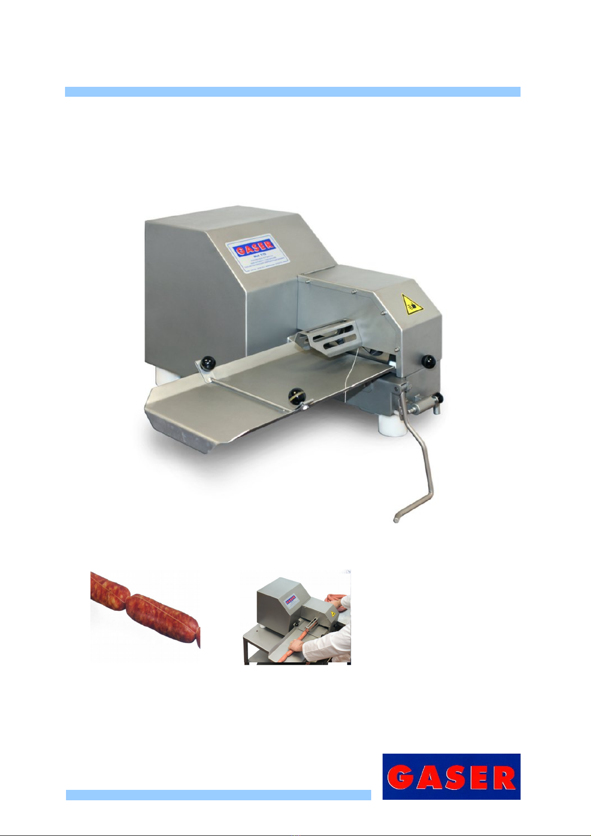
SEMIAUTOMATIC TYING MACHINE
Mod. T-70

INDEX
1. INDUSTRIAS GASER........................................................................................................................ 3
2. EC DECLARATION OF CONFORMITY..............................................................................................4
3. HYGIENE CERTIFICATE................................................................................................................... 5
4. INTRODUCTION................................................................................................................................ 6
4.1 Sa ety.......................................................................................................................................... 6
4.2 Hygiene....................................................................................................................................... 6
5. TECHNICAL SPECIFICATIONS......................................................................................................... 7
6. RECEIPT AND START-UP.................................................................................................................. 8
6.1 Receipt........................................................................................................................................ 8
6.2 Start-up........................................................................................................................................ 8
7. CLEANING....................................................................................................................................... 12
8. MAINTENANCE................................................................................................................................ 13
9. TROUBLESHOOTING...................................................................................................................... 14
10. GENERAL DIAGRAM.....................................................................................................................15
10.1 Overview.................................................................................................................................. 15
10.2 Tying machine gears overview.................................................................................................19
10.3 Tying machine gears with tying tube........................................................................................20
10.4 Tensioner with thread guide overview......................................................................................21
10.5 Drive gear overview................................................................................................................. 22
10.6 Drive sha t overview................................................................................................................ 23
10.7 Intermediate sha t overview..................................................................................................... 24
10.8. Filter regulator with pressure gauge unit.................................................................................25
11. PNEUMATIC DIAGRAM................................................................................................................. 26
-2-

1. INDUSTRIAS GASER
Since its oundation in 1969, INDUSTRIAS GASER has specialised in manu acturing a range o
stainless-steel machinery or the meat industry.
Since 1985 we have constantly developed technology or GASER-brand hamburger- orming
machines, developing a distinctive system based on a SIMPLER, MORE EFFECTIVE AND MORE
ECONOMICAL TECHNIQUE.
In the 1990s, INDUSTRIAS GASER expanded into markets in various countries around the world, and
not just in the hamburger sector.
We are aware that our work would be o no value without the trust o our existing clients and partners
or the interest shown by those who wish to join them.
We thank them all.
INDUSTRIAS GASER GASER EUROPA
Salt, Girona, SPAIN L’viv, UKRAINE
INDUSTRIAS GASER Ctra, Bescanó, 15, Pol. Torre Mirona 17190 Salt (Girona) - Spain
Tel. 34 972 23 65 72 | Fax 34 972 23 63 66 | Whatsapp: (34) 679 49 65 06
email: gaser@gaser.com
GASER EUROPA вул.Б.Лепкого,1 81160 смт.Щирець Пустомитівский р-н Львівська область
Украіна - Ukraine
Tel. 38 (03230) 67251/84
Fax 38 (03230) 67191
email: gasereuropa@gaser.com
For more in ormation about the company and its products: www.gaser.com
-3-

2. EC DECLARATION O CON ORMITY
We declare under our responsibility that the ollowing machine:
Brand: GASER
Model: T-70
Serial no.
Year o construction:
is in con ormity with the ollowing regulations
UNE-EN ISO 12100:2012
UNE-EN ISO 14120:2016
UNE-EN ISO 14121-1:2008
UNE-EN ISO 13849-1:2008/AC:2009
UNE-EN ISO 4414:2011
and is in con ormity with the ollowing directives
Machinery directive: 2006/42/CE
It is orbidden to make any change or modi ication to the machine without the prior written permission
o our technical department. Use o the machine in these conditions could cause accidents, in which
case INDUSTRIAS GASER S.L. accepts no liability or the improper use o the machine.
Salt,
CARLOS GARGANTA SERRAMITJA
TECHNICAL DIRECTOR INDUSTRIAS GASER S.L.
-4-
3. HYGIENE CERTI ICATE
We declare the machine:
Brand: GASER
Model: T-70
Serial no.
Year o construction:
is in con ormity with the ollowing regulations
Regulation (EC) 1935/2004, materials and articles in contact with ood, repealing Directives
80/590/EEC and 89/109/EEC.
This means that all o the types o steel and plastic rom which the machine is constructed and which
are in contact with the meat comply with the hygiene rules and regulations in orce.
* Plastic material: polyethylene terephthalate (PETP), white, density 1.37 g/cm3,
Manu actured in accordance with DIN 50014.
* Stainless steel: AISI 304, manu actured in accordance with European regulations EN-10088,
Chemical composition: C≤0.07% Si≤0.75% Mn≤2% Cr=18-19% Ni=8-10%
Salt,
CARLOS GARGANTA SERRAMITJA
TECHNICAL DIRECTOR INDUSTRIAS GASER S.L.
-5-

4. INTRODUCTION
Be ore using or handling the machine, you must read this manual care ully.
The instructions in this document are, whenever possible, accompanied by illustrations to help with
understanding o how to start, use and clean the machine.
This manual is subject to amendment.
4.1 Safety
It is orbidden to make any change or modi ication to the machine without the prior written permission
o our technical department. Use o the machine in these conditions could cause accidents, in which
case INDUSTRIAS GASER S.L. accepts no liability or improper use o the machine.
The machine has been designed or use with ood products and must be used in the way described in
this manual. Any use other than the speci ied one will involve risk or the user and or the machine.
INDUSTRIAS GASER S.L. accepts no liability either or damage to the machine or personal injury or
injury to third parties that this use might cause.
4.2 Hygiene
All o the materials used in the manu acture o the machine and which come into contact with ood
comply with Regulation 1935/2004. Consequently, the machine has the CE mark.
It is not recommended to use detergents containing chlorine, any o its derivatives or any other product
that could damage the construction materials o the machine.
-6-

5. TECHNICAL SPECI ICATIONS
1. Type o tying: continuous thread
2. Uses bobbins o thread (mounted on a cone)
3. Pneumatic operation (4-6 kg/cm2)
4. No electricity supply required.
5. Uses air at normal velocity (80 litres/minute)
6. Knee-operated control with attachment or automatic tying
7. 54 mm inlet
8. Adjustable choking
9. Speed adjustable rom 50 to 140 operations/minute
10. Tying with three turns o the thread
11. Table-mounted machine (650 × 500 × 700 mm stainless steel table with 4 wheels) (optional)
12. Very easy to clean
13. Measurements 650 × 380 × 420 mm
14. Machine weight: 42 kg
15. Made rom stainless steel.
-7-
6. RECEIPT AND START-UP
6.1 Receipt
When you receive the machine, you must irst check that it is in per ect conditions, without any
damage, dents or knocks.
I there is any problem, we advise you noti y the distributor or INDUSTRIAS GASER S.L. directly.
6.2 Start-up
1. It is important that when starting to tie cured meat products, the machine is completely clean to
ensure it works properly.
2. It must be connected to a compressed air network. Its normal operating pressure is 4 to 6 kg/cm2,
depending on how quickly you want it to operate.
3. Check that the cone or holding the thread bobbin (Pos. 2, tying machine gear overview) is raised.
I it is not, let the air out and put it in its position manually.
4. Insert the thread according to the instructions below.
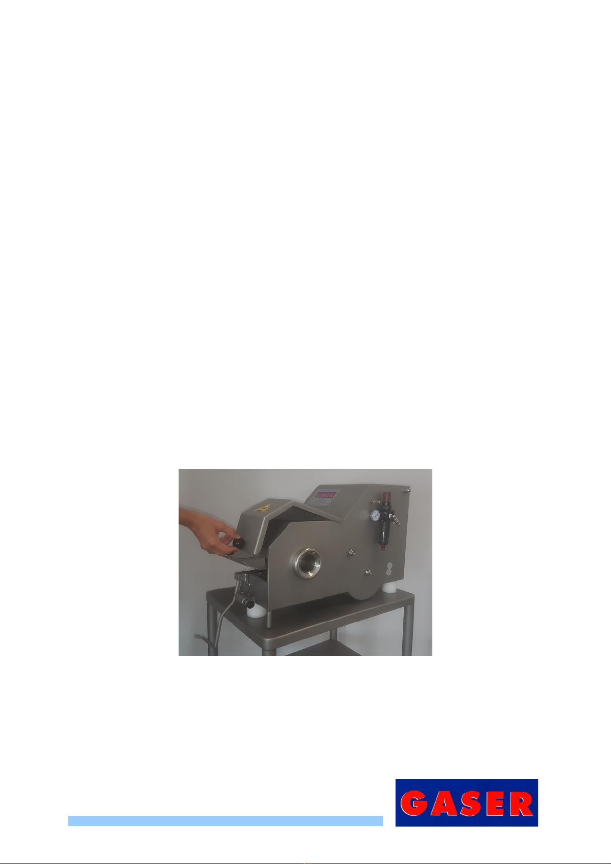
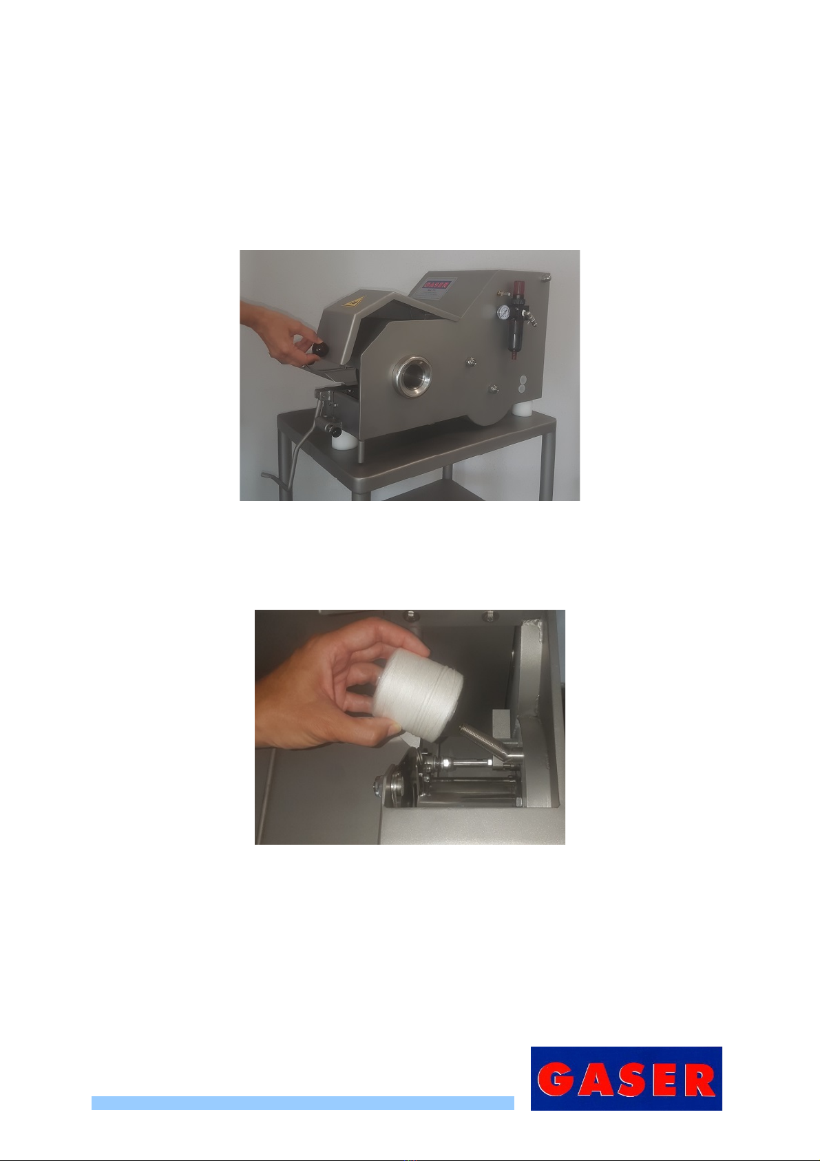
4.1 Open the upper protection (Pos. 27, overview) using the knob (Pos. 29, overview).
Image 1. Opening the lid
-8-

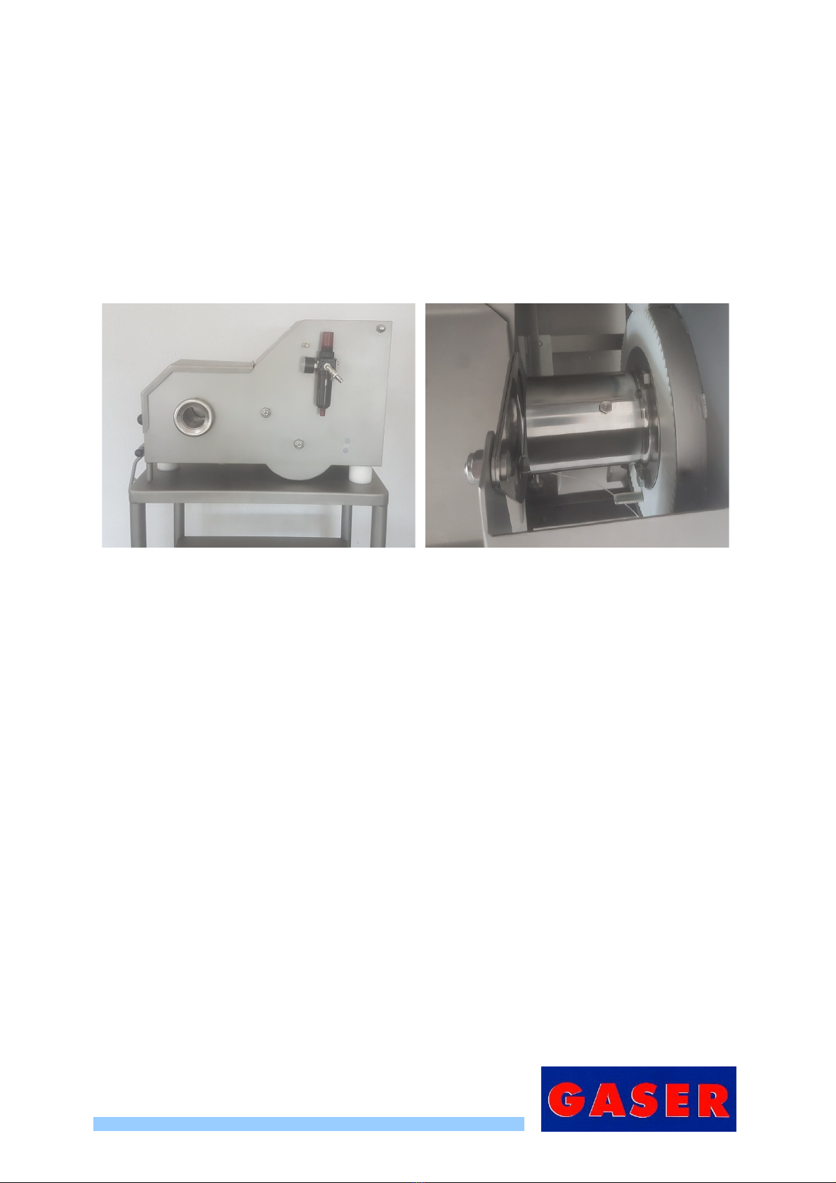
4.2 Load the thread bobbin on to the articulated sha t (Pos. 2, Tying machine gears with tying
tube overview), turning it to the right to tighten and screw it on.
Image 2, Loading bobbin on sha t
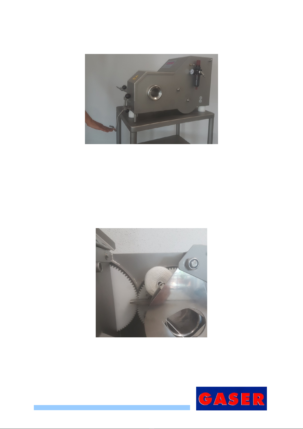
4.3 Pass the thread through the hole in the blades
Image 3, Passing thread through hole in blades
4.4 Pass the thread through the brake (Pos. 2, tensioner with thread guide overview) and
through the thread guide (Pos. 3, tensioner with thread guide overview).
Image 4.1, Passing thread through brake Image 4.2, Passing thread through
thread guides
Image 4.3, End result
-9-
4.5 Do the operation twice by activating the knee-operated control (Pos. 31, overview) without
moving the meat orwards so that the thread is ixed.
Image 5, Operating knee control
5. On the right o the machine there is an air- low control. By turning it, you can adjust the air low
and consequently the speed o work.
6. When adjusting the speed o operation, do not set it to the minimum speed as in this case the
machine will not receive enough air and will stop working.
7. When starting to operate, the thread bobbin should be in the 11 o’clock position.
Image 6, 11 o’clock position
-10-

8. I you want to work continuously, insert the lever ixing sha t (Pos. 32, overview).
Image 7, Inserting lever ixing sha t
9. During operation, it is necessary to ensure that the bobbin does not come o its support.
-11-
7. CLEANING
When inishing production, the machine must be cleaned. No parts o the machine need to be
dismantled to do this:
1. Li t the upper protection (Pos. 27, overview) using the knob (Pos. 29, overview).
Image 8, Opening the lid
2. Remove thread bobbin. I this is not removed when cleaning, this can encourage the growth o
bacteria owing to the damp.
Image 9, Removing thread bobbins
3. The machine is ready or cleaning, i possible, with high-pressure water. Once it has been cleaned,
dry it well, i possible, with air.
4. To reassemble the machine, repeat the process described above in reverse order.
-12-
8. MAINTENANCE
1. Lubricate the three lubrication points with thin ood-grade oil. Two o them are located on the right-
hand side o the machine and the other in the twisting mechanism. To be able to lubricate the
twisting mechanism, release the air pressure and give the twisting mechanism hal a turn until the
thread bobbin is at the bottom and the lubrication point at the top.
When the machine is new, we recommend lubricating it every 8 hours o work or when it will be
stopped or more than 2 days.
Image 10, Side lubrication points Image 11, Twisting mechanism lubrication point
2. Periodically check the condition o the springs, bearings, and bushings.
3. Periodically check the condition o all moving parts.
4. Periodically check the condition o the pneumatic elements and their connections.
5. Periodically check the general condition o the machine.
-13-
9. TROUBLESHOOTING
Problem Cause Solution
The machine does not start
Machine unplugged See manual “6.2. Start-up”, point 2
Set the low to its minimum See manual “6.2. Start-up”, point 6
Pneumatic ault See manual “8. Maintenance”, point 4
The machine does not operate at
the desired speed
Insu icient inlet air pressure See manual “6.2. Start-up”, point 2
Poorly adjusted air entry low See manual “6.2. Start-up”, point 6
Internal air leak See manual “8. Maintenance”, point 4
Lacks lubrication See manual “8. Maintenance”, points
1 and 2
-14-

10. GENERAL DIAGRAM
10.1 Overview
Number Description Reference Units
1 T-70 TYING MACHINE CHASSIS 70010100 1
2 FEET 70130100 3
3 LEG LOWER WASHER 70130200 3
4 TYING CORE NUT 00070400 1
5 CYLINDER-GEARWHEEL CONNECTION SHAFT 70090300 1
6 T-72 METAL GEAR 70090800 1
7 T-72 TYING MACHINE INTERMEDIATE GEARS 70090900 1
8 T-72 DRIVE CYLINDER SPACER 70091000 1
9 T-72 CYLINDER UPPER SHAFT 70091100 1
10 TWIN STAINLESS Ø40 × 100 CYLINDER PLEASE CONSULT 1
11 ANTI-ROTATION BUSHING SI0509HFCB30 1
12 ANTI-ROTATION BUSHING SI0509HFL2530 1
13 CHOKING CYLINDER SHAFT 00020100 1
14 UPPER VANE SHAFT 00020500 1
15 CRANK AXLE 00020600 1
16 CHOKE BLADES LOWER GUIDE 00020700 2
17 TYING UNIT CRANK 00022400 1
18 CHOKE BLADES 00022500 2
19 TYING DEVICE CHOKING ROD 00022600 2
20 STAINLESS STEEL FORK AND PIN UNIT 00670000 1
21 BLADE SLOT PROTECTION 70022700 1
22 25/50 STAINLESS CYLINDER NE1315025/050I 1
23 NYLON WASHER SI0216211002NY 2
24 PLAIN BEARING SI0409010008010 2
25 PLAIN BEARING SI0409012010010 4
26 CHOKING CYLINDER RUBBER STOP SI0602TG0190813 1
27 UPPER PROTECTION 70160100 1
28 BACK COVER 70160801 1
29 BALL HANDLE Ø30 M8 SI0212ESF32M08 3
30 KNEE-OPERATED CONTROL SHAFT 70200200 1
31 T-71 KNEE OPERATED CONTROL 70201100 1
32 LEVER ATTACHMENT SHAFT 70201200 1
33 LIMIT SWITCH SHAFT 70201300 1
34 LENGTH MARKER 70230200 1
-15-

35 T-71 OUTLET PLATFORM 70232100 1
36 NICKEL VALVE EXTENDER 15080500 1
37 SILENCER 70080100 1
38 KNEE-OPERATED CONTROL INNER SWITCH 70081300 1
39 SHARP EDGE HAZARD STICKER PA0230PT 1
40 T-72 CONTROL PANEL PA0230COMT72 1
41 SPRING SI011407209.23.5 1
42 NOT VALVE NE0215NOTC 1
43 NOT VALVE BASE 1/8” NE03157097K18 1
44 MANIFOLD NE0315DJ5214 2
45 E-28310 LIMIT SWITCH NE0315E28310 1
46 T-70 DRIVE GEARS LIMIT SWITCH NE0315ER18310 2
47 DISTRIBUTOR 40 × 40 × 20 1/4” NE0315R4040201 1
48 INTERNAL DISCHARGE VALVE NE0315VDI14 1
49 TYING MACHINE SPEED CONTROL NE0815RCW18 1
50 NICKEL VALVE VCMS32M08 3/2 1/8” 77570000 1
51 FILTER REGULATOR UNIT WITH PRESSURE
GAUGE 77550000 1
Figure 1, Standard overview 1
-16-

Figure 2, General overview 2
Figure 3, General overview 3
-17-

Figure 4, Pneumatic elements
-18-

10.2 Tying machine gears overview
Re . 77620000
Number Description Reference Units
1 TYING MACHINE GEARS 00070100 1
2 THREAD BOBBIN SUPPORT CONE 00070500 1
3 THREAD TENSIONER INERTIA BRAKE BASE 70071100 1
4 THREAD TENSIONER INERTIA BRAKE SUPPORT 70071200 1
5 THREAD TENSIONER INERTIA BRAKE
COUNTERWEIGHT
70071300 1
6 THREAD TENSIONER INERTIA BRAKE SHAFT 70071400 1
7 INERTIA STOP STUD 70071600 2
Figure 5. Tying machine gears overview
-19-
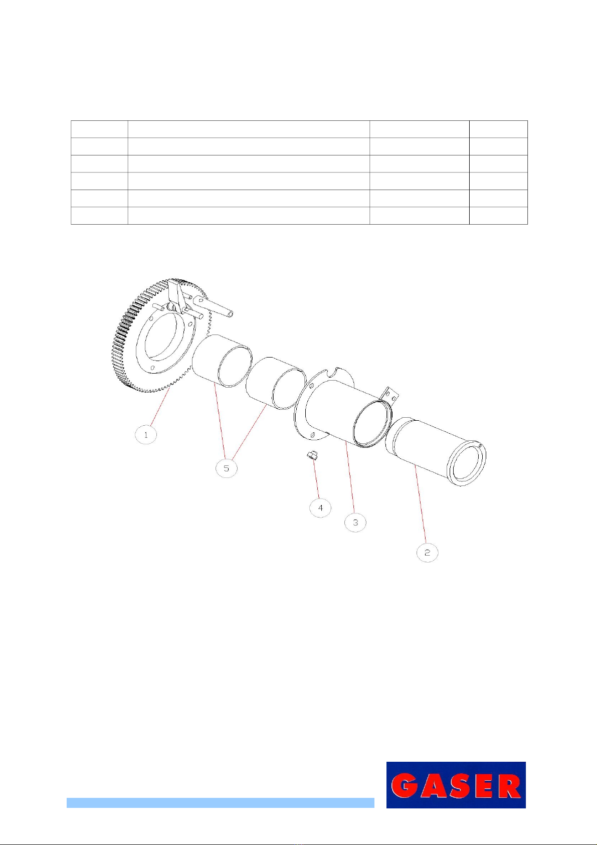
10.3 Tying machine gears with tying tube
Re . 77530000
Number Description Reference Units
1 TYING MACHINE GEARS OVERVIEW 77620000 1
2 TYING CORE 00070200 1
3 TYING TUBE 00070300 1
4 TYING LUBRICATION POINT SI0122EHCM8 1
5 PLAIN BEARING SI0409070065050 2
Figure 6, Tying machine gears with tying tube
-20-
Table of contents
Other GASER Commercial Food Equipment manuals


