Gatco Cross Flow Aeration User manual
MANUAL CF 1
Cross Flow Aeration Manual
NOTE: Gatco Manufacturing believes in continuous improvement and as such, manuals, brochures and
specifications are subject to change without notice.
Revision: Dec 31, 2018 Manual Part# MANUAL CF
MANUAL CF 2

MANUAL CF 3
Table of Contents
1.0 Introduction......................................................................................................................................................8
2.0 Safety................................................................................................................................................................9
2.1 General.........................................................................................................................................................9
2.2 Safety Harness/Restraint .............................................................................................................................9
2.3 Ladder ........................................................................................................................................................10
2.4 Maintenance .............................................................................................................................................10
2.5 Assembly ....................................................................................................................................................10
3.0 Installation......................................................................................................................................................11
3.1 General Installation....................................................................................................................................11
3.2 Assmbly Tools Required .............................................................................................................................11
3.3 Flat Bottom Grain Bin.................................................................................................................................12
3.4 Hopper Bottom Grain Bin...........................................................................................................................21
4.0 Operation .......................................................................................................................................................29
5.0 Maintenance...................................................................................................................................................30
6.0 Troubleshooting .............................................................................................................................................31
7.0 Specifications..................................................................................................................................................31
8.0 Warranty.........................................................................................................................................................32

MANUAL CF 4

MANUAL CF 5
Warranty Registration Form
Cut to remove and mail, fax or email to Gatco Manufacturing to register.

MANUAL CF 6

MANUAL CF 7
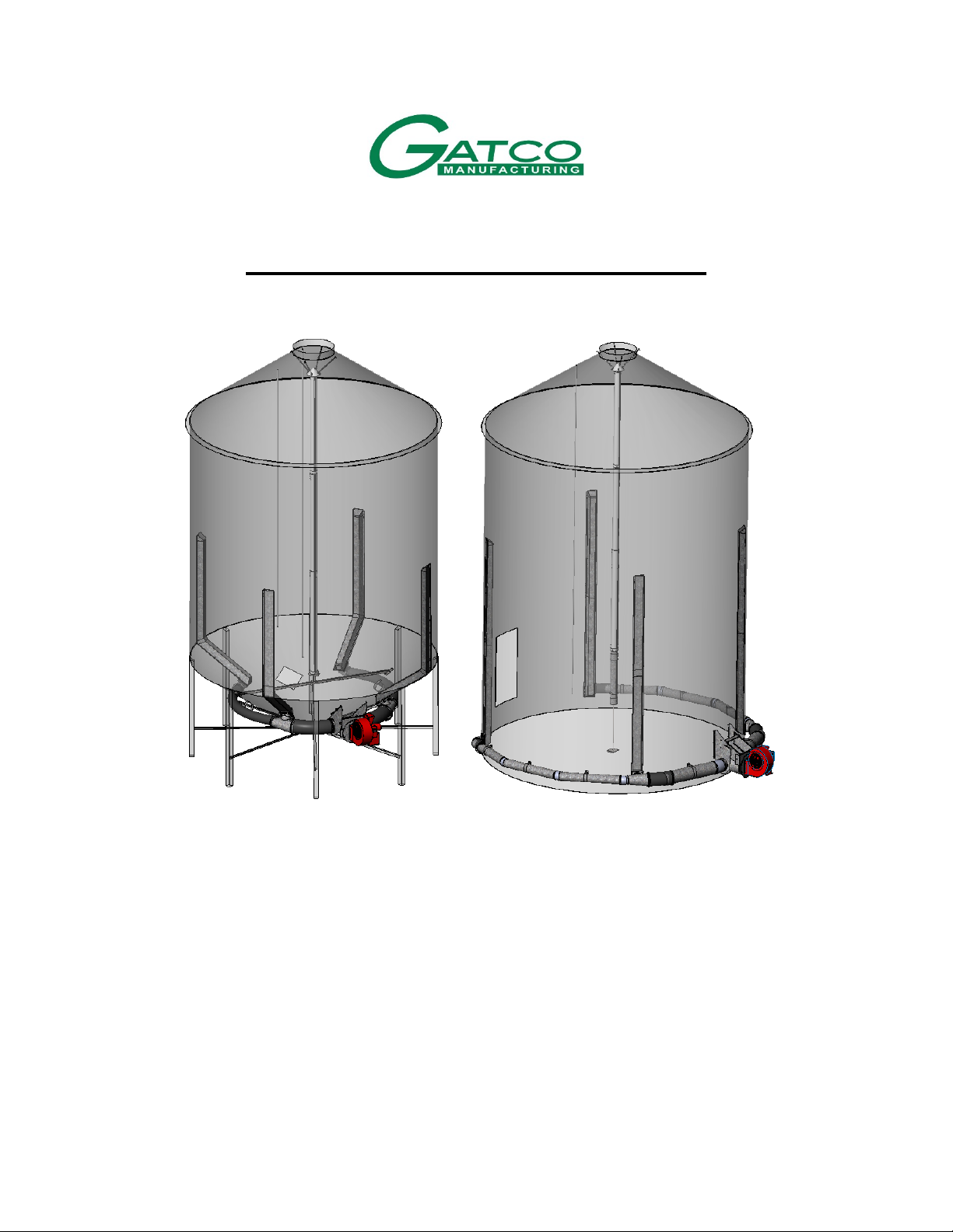
1. Introduction
Thank you for purchasing a Gatco Manufacturing Cross Flow Aeration System. This system will dry grain
using natural grain aeration drying by pushing air horizontally from the bin wall to the center GrainAir
Tube. The air can then quickly exhaust up through the GrainAir Tube through the bin lid. When the
fan(s) aren’t used, the center GrainAir tube will continue to allow any excess heat to continue to exhaust
out of the bin all year long without any power required through the Vent-a-lid.
By following the instructions and procedures in this manual you will be able to safely store grain, prevent
grain clumping, mold and insect problems and ensure the long, trouble free use of this system. Ensure all
people using this system have read and understood this manual. Ensure that the manual is always
available for future reference.
Note: This system can only be used with grain. It cannot be used with fertilizer as damage to the system
will occur.

MANUAL CF 8
2. Safety
2.1.General
This manual contains information that is important for you, the owner/operator, to know and
understand. This information relates to protecting personal safety and preventing equipment
problems. It is the responsibility of the owner/operator to inform anyone operating or working in
the area of this equipment of these safety guidelines. To help you recognize this information, we
use the symbols that are defined below. Please read the manual and pay attention to these
sections. Failure to read this manual and its safety instructions is a misuse of the equipment and
may lead to serious injury and/or death.
DANGER - indicates an imminently hazardous situation which, if not avoided, will result in in
serious injury or death.
WARNING - indicates a potentially hazardous situation which, if not avoided, could result in
serious injury or death.
CAUTION - indicates a potentially hazardous situation which, if not avoided, may result in
minor or moderate injury.
NOTICE - indicates a potentially hazardous situation which, if not avoided, may result in
property or equipment damage.
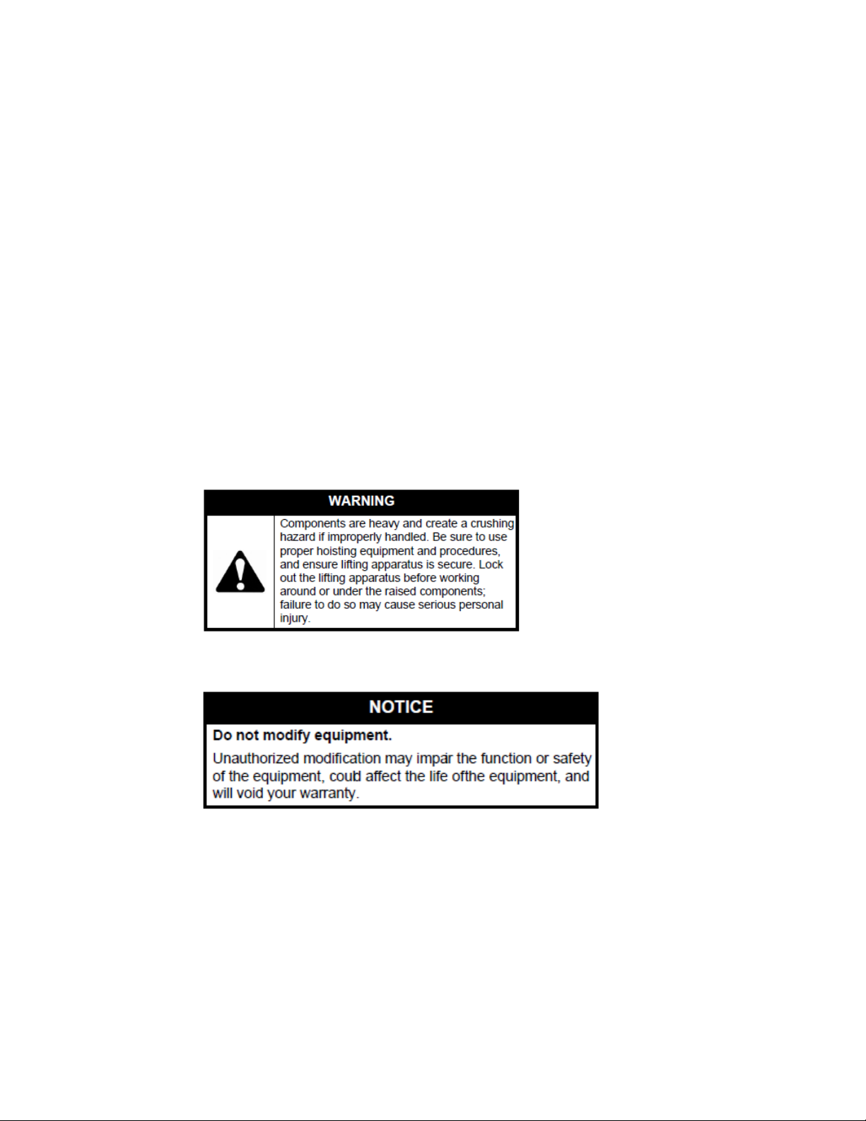
•Use this equipment for its intended purposes only.
•Do not modify this equipment in any way as it may impair its safety, function and
longevity and will void the warranty.
•Wear appropriate protective equipment (i.e. gloves, glasses, foot wear, hearing
protection, etc.)
2.2.Safety Harness/ Restraint
•Follow all local safety regulations in the use of a safety harness and fall restraint system.
•Do not use equipment that has missing and/or damaged safety decals and instructions.
•Do not use equipment that is damaged in any way.
MANUAL CF 9
2.3.Ladder
•Follow all safety instructions provided with the ladder. If not legible, please contact the
ladder manufacturer directly to ensure that you have all safety instructions.
•Do not use equipment that has missing and/or damaged safety decals and instructions.
•Do not use equipment that is damaged in any way.
2.4.Maintenance
•Use only genuine Gatco replacement parts. Use of unauthorized parts will void the
warranty.
•Do not modify any components without authorization from Gatco. Modifications can
result in serious personal injury and/or equipment damage.
2.5.Assembly
•Read and understand the instructions before proceeding to assembly of this product.
•Some of the components can be heavy and/or difficult to handle so always use proper
tools, lifting devices, support stands for the job.
•Always have two or more people assembling this equipment.

MANUAL CF 10
3. Installation
3.1.General
Before beginning installation ensure all assemblers have read and fully understood this
manual.
3.2.Assembly Tools Required
•Electric drill and impact driver
•Level
•Tape measure 100ft
•Steel cutting tools (i.e. metal reciprocating saw)
•Socket and wrench set
•Hammer
•Drill bit 9/32” for bin wall self-threading screws (is supplied)
•Drill bit 11/32” for 5/16” bolts on inlet bolt holes (not supplied)
•Marker
•Caulking gun
•Ladder
•Lifting device (i.e. rope, slings) with minimum 500lb rating
•Fall restraint if required by local regulations
•Ground fault interrupt protected electrical cord(s)
•Eye, foot, head, and hand protection (safety glasses, steel-toed boots, hard hat, work
gloves)
•First-aid kit
•Wire cutter to cut rubber hose steel helix

MANUAL CF 11
3.3.Flat Bottom Grain Bin
Caution: use proper eye and hand protection when handling parts to prevent injury to
yourself and others.
3.3.1. Column Assembly, Flat Bottom Bin
1. See Figure 3.3.1 below. Join the pre-assembled upper column assembly to the
lower column assembly using 4=SELF-DRILLING SCREWS (per joint).
2. Once assembled, move column assemblies into the grain bin and set on the floor.
Figure 3.3.1: Flat Bottom Bin Column Assembly

MANUAL CF 12
3.3.2. Column Location and Hole Placement Layout
1. See Figure 3.2.2a below. Mark the location of the fan transition opposite the grain
bin door. For other fan locations, contact Gatco Head Office.
2. Measure the entire outside circumference of the bin.
IMPORTANT: Be aware of the location of any bolted seams on the grain bin. The column
must be able to be pressed tightly against the inside bin wall. Any protrusions such as bolts
may prevent this. Because of the curvature of the grain bin, it may be possible to line up
the column with the row of bolts and still have it press tightly against the bin wall.
3. For a 4 column system use the circumference divided by 4 to give you the distance
between the columns. From the fan transition, measure over 1/8 of the
circumference to get the first column measurement. The next column will be 1/4 of
the circumference from there.
4. For a 6 column system use the circumference divided by 6 to give you the distance
between the columns. From the fan transition, measure over 1/12 of the
circumference to get the first column measurement. The next column will be 1/6 of
the circumference from there.
5. For an 8 column system use the circumference divided by 8 to give you the distance
between the columns. From the fan transition, measure over 1/16 of the
circumference to get the first column measurement. The next column will be 1/8 of
the circumference from there.
Figure 3.3.2a: Hole Placement in Flat Bottom Bin (4 column shown)

MANUAL CF 13
Caution: use proper eye and hand protection when cutting metal to prevent injury to
yourself and others.
6. Using INLET HOLD TEMPLATE, cut holes in the grain bin wall at the locations
indicated in Figure 3.2.2b below.
IMPORTANT: If the grain bin has a fixed bin sweep installed, the holes in the bin walls may
need to be located higher for bin sweep to pass under column.
Figure 3.3.2b: Hole Cut-out Flat Bottom Bin- INLET HOLE TEMPLATE
MANUAL CF 14
3.3.3. Column Mounting on Flat Bin Wall
1. Position all column assemblies on the inside of the bin
Important: column assemblies are best handled with a minimum of 2 people. Longer
columns will require more people to hold in place while fastening column to the bin wall.
2. Position electric driver with ½” socket, electric drill with 9/32”bit and the 5/16 X 1”
SELF-THREADING SCREWS where they can be easily reached.
3. Lift and insert the inlet (round pipe at bottom) of the pre-assembled column
through hole in bin wall.
4. Level and the column assembly to the bin wall and have first person hold column in
place.
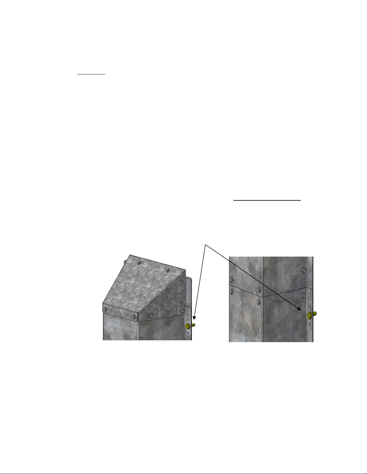
5. See Figure 3.3.3a below. Second person will pick the column side hole that aligns
with the bin wall corrugation and drill through the bin wall with the electric drill and
9/32” bit.
6. Once hole is drilled then use electric driver with socket to install 5/16 X 1”SELF-
THREADING SCREWS. Ensure that there is a tight seal and the bin wall is not
dimpled or dented when the bolt is tightened up. Do not overtighten bolts. If
overtightened, you may need to install 5/16” UNC nut on the outside of the bin (not
supplied).
Figure 3.3.3a: Top of Column Assembly & Mid-joint of Column Assembly
7. Repeat for both sides of the column assembly at each joint/top to complete install
of 5/16 X 1” SELF-THREADING SCREWS (yellow plated).
5/16 X 1” SELF-THREADING SCREWS (yellow plated)
MANUAL CF 15
8. See Figure 3.3.3b below. Once the column assembly has been secured to the bin
wall, the INLET can be bolted through the bin wall. Use an electric drill with 11/32”
bit (not supplied). From the inside of the bin, drill all 4 holes through the inlet
plate.
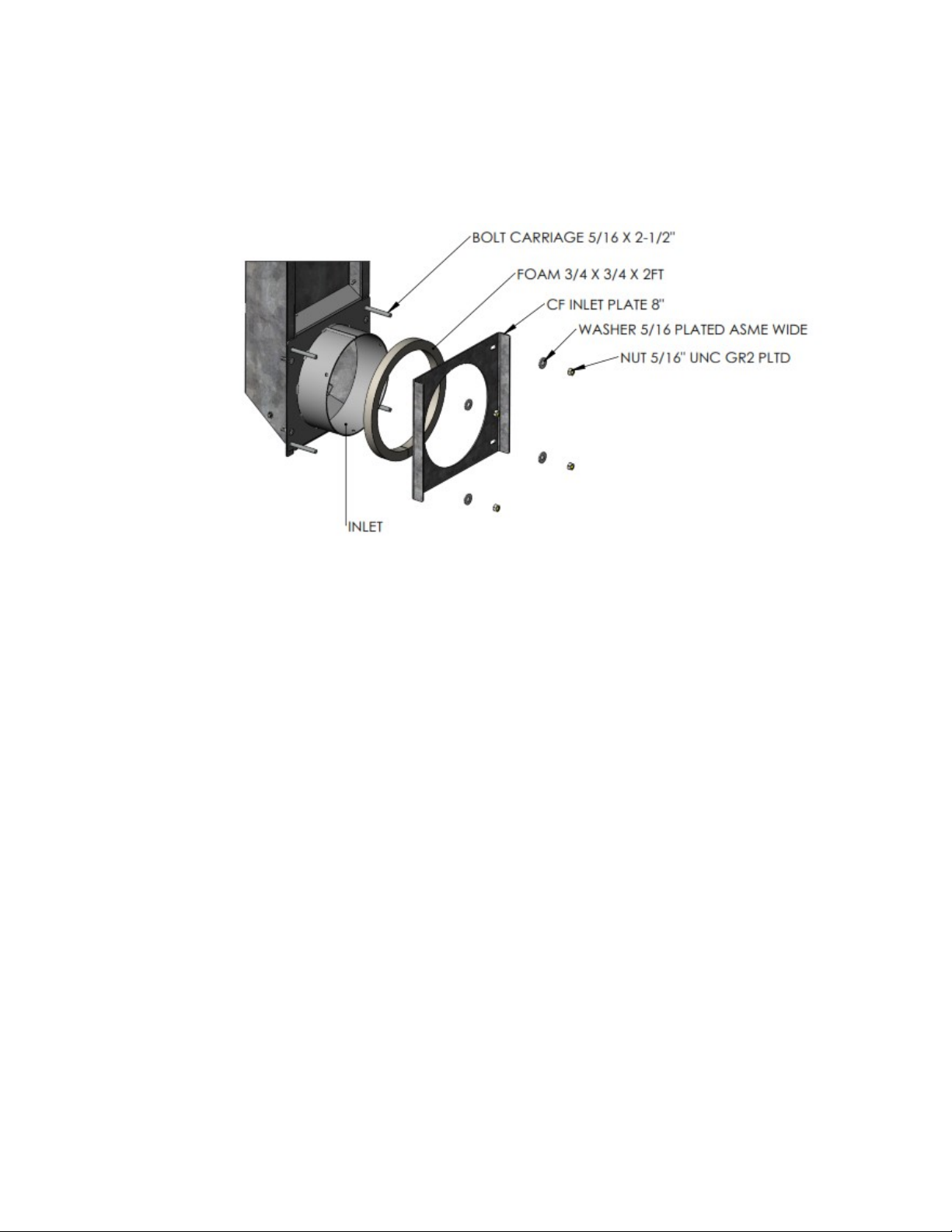
Figure 3.3.3b: Inlet Assembly
9. On the outside of the bin, install FOAM between the bin wall and the outer CF
INLET PLATE 8”.
10. Install the 4=5/16 X 2-1/2”CARRIAGE BOLTS from the inside of the bin. Have
second person on the outside of the bin install 5/16” NUTS & WASHERS on the
outside of the bin wall.
11. Tighten each nut a little bit at a time to ensure that the foam is being compressed
uniformly. Foam can be compressed to 1/8 to ¼”.
12. On the inside of the bin, use MINIMUM EXPANSION SPRAY FOAM to seal the
column to the bin wall.

MANUAL CF 16
3.3.4. Flat Bottom Bin Transition Assembly
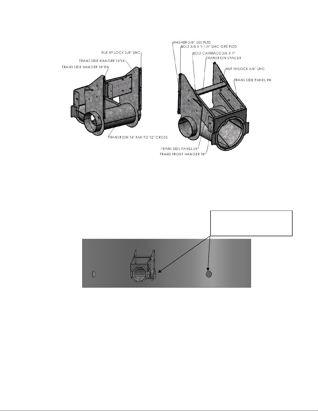
1. See Figure3.3.4 below, loosely assemble all components.
2. Once all components are installed, tighten all hardware.
3. Place the FAN TRANSITION against the bin wall. You will require at least 2 people to
lift and block FAN TRANSITION in place. Double check to ensure that the center of
the FAN TRANSITION is the same height as the 8” inlet holes in the bin walls.
4. Once confirmed that the FAN TRANSITION is positioned properly in relation to the
8” inlet holes, use electric drill and 3/8”bit and drill 6 holes through the bin wall
and bolt the FAN TRANSITION to the bin using bolts, locknuts and washers.
5. Tighten all bolts.
NOTE: For heavy aeration fans, the customer may need to add cable/chain (not supplied) to
provide adequate support to the FAN TRANSITION and aeration fan.
MANUAL CF 17
Figure 3.3.4: Flat Bottom Fan Transition Assembly
Center Fan Transition with Wall
Column Holes

MANUAL CF 18
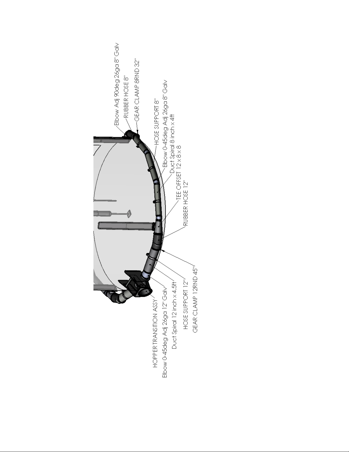
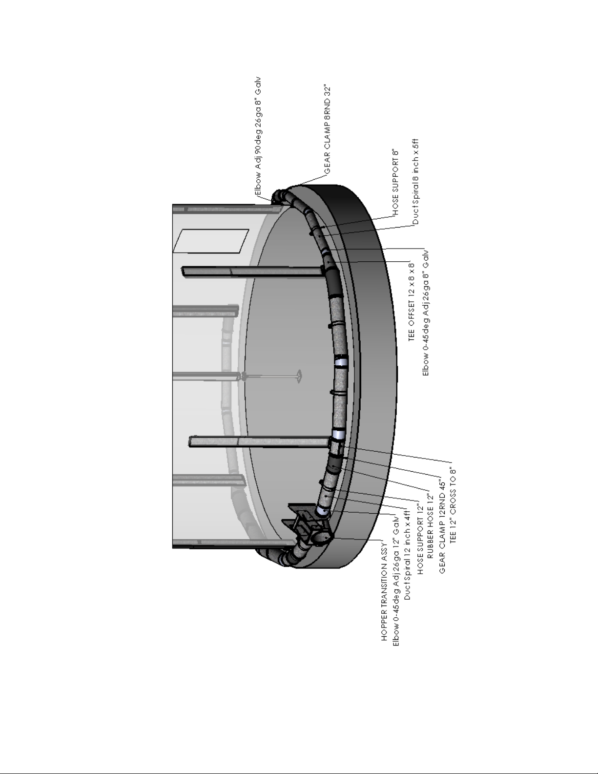
3.3.5. Outside Ducting Assembly
1. See Fig 3.3.5a for 4 vertical columns.
2. Starting at the Transition 18”, go to first COLUMN INLET and install TEE OFFSET
12x8x8 into inlet on column (12” end facing TRANSITION 18”). Fasten with 3= SELF-
DRILLING SCREWS and silicone TEE to INLET. Repeat on other side of transition.
NOTE: If there are 6 COLUMNS on the bin see Fig 3.3.5b, install TEE 12x12x8 on first inlet,
TEE OFFSET 12x8x8 on second inlet and ELBOW 90deg 8” on third inlet.
NOTE: If there are 8 COLUMNS on the bin see Fig 3.3.5c, then install TEE 12x12x8 on first
and second inlet, TEE OFFSET 12x8x8 on third inlet and ELBOW 90deg 8” on fourth
inlet.
3. On the second COLUM INLET, install the ELBOW 90deg 8”. Fasten to the COLUMN
INLET using 3= SELF-DRILLING SCREWS. Silicone ELBOW to INLET.
4. Install the ADJUSTABLE ELBOW 12” onto the FAN TRANSITION using self-drilling
screws.
5. Direct the ADJUSTABLE ELBOW 12’ to point to the TEE OFFSET 12x8x8.
6. Attach a 5ft piece of SPIRAL DUCTING 12” onto the ADJUSTABLE ELBOW 12’. Fasten
with 3= SELF-DRILLING SCREWS.
7. Measure, cut and install RUBBER HOSE 12” to connect the SPIRAL DUCTING 12” to
the TEE 12x12x8. Use 2=GEAR CLAMP 12” to secure the RUBBER HOSE.
8. Attach a 5ft piece of SPIRAL DUCTING 8” onto the TEE 12x12x8. Fasten with 3=
SELF-DRILLING SCREWS.
9. Attach an ADJUSTABLE ELBOW 8” onto SPIRAL DUCTING 8”. Fasten with 3= SELF-
DRILLING SCREWS.
10. Attach a 5ft piece (trim if required) of SPIRAL DUCTING 8” onto the ADJUSTABLE
ELBOW 8”. Fasten with 3= SELF-DRILLING SCREWS.
11. Measure, cut and install RUBBER HOSE 8” from the SPIRAL DUCTING 8” to the
ELBOW 90deg 8”. Use 2=GEAR CLAMP 8” to secure the RUBBER HOSE.
12. Level the SPIRAL DUCTING 8” and install a HANGER STRAP 8” to hold the pipe in
place.
13. Seal all INLETS with silicone.
14. Seal all ELBOWS and SPIRAL DUCTING ends with Duct Sealant.
MANUAL CF 19
Figure 3.3.5a: Flat Bottom Outside Ducting (4 vertical columns)
MANUAL CF 20
Figure 3.3.5b: Flat Bottom Outside Ducting (6 vertical columns)
Table of contents
Other Gatco Farm Equipment manuals

Popular Farm Equipment manuals by other brands

EMAK
EMAK Transporter TN 3500 Use and maintenance

Avery Dennison
Avery Dennison Eartrace RH7 Quick start quide

Gillison's Variety Fabrication
Gillison's Variety Fabrication GVF 10,000 owner's manual

AGCO
AGCO GSI PNEG-1826 owner's manual

Unverferth
Unverferth 1000 manual

AGROFROST
AGROFROST Frostbuster F252 Operating & maintenance instructions

WOOD'S POWR-GRIP
WOOD'S POWR-GRIP MRTALP Series instructions

AG
AG AG Mini instruction manual

Land Pride
Land Pride RTA2064 Operator's manual

ARAG
ARAG 520005 Installation, use and maintenance

TESLA Wheels
TESLA Wheels PT owner's manual

Lubing
Lubing Pad-Climate-System Assembly instructions and operating manual


