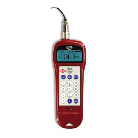
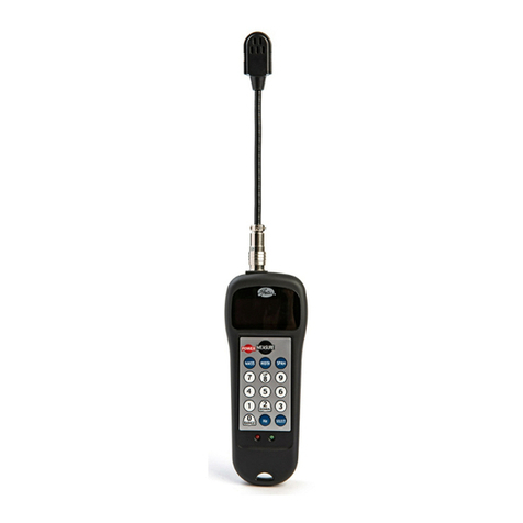
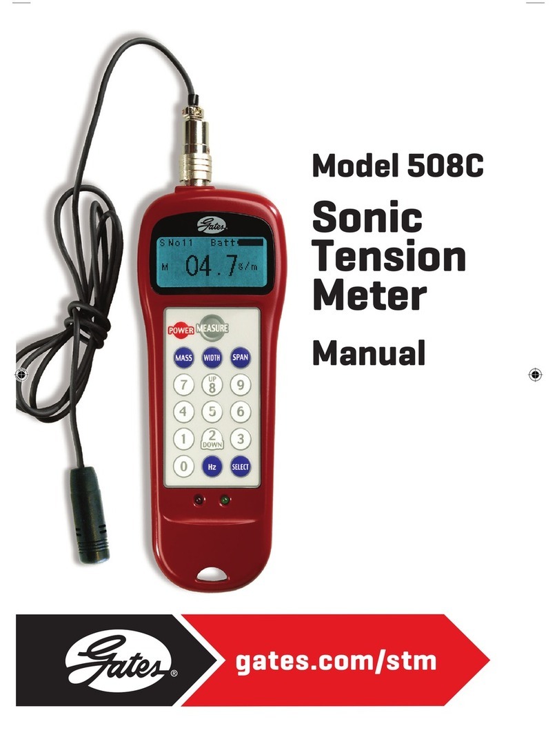
Gates 508C User manual

UK
F
D
E
NL
I
PL
RU
CZ
1
• Gates Sonic tension meter manual
• Manuel d’utilisation pour
le tensiomètre Sonic Gates
• Handbuch für Gates Sonic
Vorspannungsprüfer
• Manual para el tensiómetro
Sonic de Gates
• Gebruiksaanwijzing Gates’
Sonic spanningsmeter
• Manuale d’uso per
il tensiometro Sonic
Gates
• Instrukcja obsługi
akustycznego miernika
naprężenia Sonic 508C
firmy Gates
• Руководство по
работе со звуковым
измерителем
натяжения ремней
Sonic 508C
компании Gates
• Příručka pro
Sonic měřič
napnutí
společnosti
Gates
508C

2
UK
F
I
E
NL
D
PL
R
TJ
Gates Sonic tension meter
manual
Contents Page
1. Important warnings .....................................2
2. Components of the 508C meter..................3
3. Operating procedure for the 508C meter ...4
4. Sonic tension meter operating theory ........7
5. Belt installation tension...............................8
6. Tips on using the Sonic tension meter .......8
7.
Meter recalibration for non-standard belts
..10
8. Summary of features .................................10
9. Optional accessories..................................10
10. Warranty and service .................................11
11. Belt unit weight calculation .......................11
Thank you for purchasing the Gates Sonic
tension meter. Please read this manual
thoroughly to fully utilise all the meter’s
functions.
1. Important warnings!
>Do not drop this unit. Impact of any kind
can result in damage.
>Do not disassemble the unit.
>Do not put the unit in a place where fire or
explosion is possible.
>Do not put water, solvent or any other
liquids on this unit.
>Do not leave this unit in a dusty
environment.
>Do not leave this unit where it will get hot,
such as in a car or in direct sunlight.
>Do not use volatile solvents to clean this
unit.
>Do not use this in an area where a spark
could cause an explosion.
>Do not bend the flexible arm sensor
(microphone) within 20 mm (3/4 inch)
of either end. Its construction is tubular,
and it should not be bent at sharp angles.

3
UK
F
I
E
NL
D
PL
R
TJ
2. Components
of the 508C meter
1 - Flexible sensor
2 - Sensor connector
3 - Power switch
4 - Belt unit weight key
5 - Belt width key
6 - Up button
7 - Down button
8 - Frequency range button
9 - LCD screen with backlight
10 - Measure key
11 - Belt span length key
12 - Frequency/tension display key
13 - Data selection key
14 – Batteries
2
1
3 10
9
4 11
5
6
7 12
8 13
14

4
UK
F
I
E
NL
D
PL
R
TJ
3. Operating procedure for
the 508C meter
The Sonic tension meter enables non-contact,
simple and accurate measurement of
installation tension by analysing sonic wave
action, which is related to the belt
characteristics. The sonic wave is generated
by vibrating the belt span of the stationary belt,
and it is captured by the sensor and processed
to give belt tension which is displayed digitally.
Attaching sensor
Each of the male and female connectors has
a notch on the surface. Align the notches and
push the connectors together. To disconnect,
hold the collar towards the sensor and pull out.
Turn on the power
1 “MASS”
2 “WIDTH”
3 “SPAN”
4 Storage Register Number
5 Frequency Setting
6 Battery Level Meter
Press the “Power” key and the LCD screen
displays the current input data storage register
number. To change, refer to “Input data storage
and retrieval”.
The LCD screen is back lit for use in low light
conditions. The screen and back light remain
on for up to five minutes of inactivity, and then
the unit automatically turns off. The opening
screen displays the contents of the data storage
register that was last being used when the
Sonic tension meter was turned off. Values for
(1) “MASS” (Belt Mass Constant), (2) “WIDTH”
(Belt Width), and (3) “SPAN” (Belt Span Length)
are all displayed simultaneously.
Important Note: Reasonable (non-zero)
belt constant values must be used in the
storage registers in order to receive belt
tension readings. The unit will display span
frequency values regardless of the belt
constants entered, but will display “Error”
and the red light will remain on if the
calculated belt tension value is beyond
the display range of the screen.
Enter belt unit mass
M = .g/m
(Grams per metre length – enter factors page
11-12-13-14).
Capacity available for input is from 000.1 to
999.9 g/m. Press the “Mass” key and enter
numbers on the keypad. Make sure the decimal
is placed correctly in the display panel. If your
entry is incorrect press “Mass” again, and
the cursor returns to the original position.
SNo. 01
M 999.9 g/m
W 999.9 mm/R
S 9999 mm
1
2
3
5
6
4

5
UK
F
I
E
NL
D
PL
R
TJ
Enter width or number of ribs/strands
W = .mm/#R
Capacity available for input is from 000.1 to
999.9 mm or number of ribs or strands.
For a synchronous belt, enter the width in
millimetres. For an Industrial V-belt, enter
the number of belts being measured.
For a Micro-V®belt, enter the number of ribs.
For a Polyflex®JB®or PowerBand®belt, enter
the number of strands. Enter the number of
ribs/strands only for the belt being tested.
When using the Sonic Tension Meter on
drives with multiple single or PowerBand®
or Polyflex®JB®belts, be sure to use
the appropriate mass constant and enter
the correct number of belt strands being
measured. There is no need to multiply the
mass constant by the number of ribs/strands,
as the Sonic Tension Meter will calculate
the correct total belt mass.
Example:
For a V-belt drive using four individual SPB belts
enter “1” for the belt width (“Width” key).
The Sonic Tension Meter will display the static
belt tension per individual belt. When measuring
the belt tension in the V-belt drive, make sure
the V-belts do not interfere with each other
while vibrating.
If the same drive used a 4-strand SPB
PowerBand®belt instead of single belts enter
“4” for the belt width (“Width” key). The total
belt tension for all four belts is measured as
the entire belt vibrates. The Sonic Tension Meter
will display the total static belt tension for the
PowerBand®belt (for all strands within belt).
Enter the span length
S = mm
Capacity available for input is from 0001 to
9999 mm.
The span length represents
the distance between the contact points on
adjacent pulleys/sheaves. This distance may
be measured directly, or it may be calculated
from the formula below. Calculating the span
length gives the best results.
Span length (mm) = CD2- (D - d)2
4
Where:
CD = centre distance (mm)
D = large pulley diameter (mm)
d = small pulley diameter (mm)
Input data storage and retrieval
Weight, width and span values can be stored
for up to 40 different drive systems. Press the
“Select” key to toggle through the 40 storage
registers or press a number between 0 and 39,
then enter values for the belt constants.
After this is completed, the belt values can
be recalled for a drive by simply pressing
the “Select” key and the number that
corresponds to the storage register.

6
UK
F
I
E
NL
D
PL
R
TJ
Measurement
Press the “Measure” key and the green LED
will begin flashing. It will flash until a signal
is received by the sensor. Tap the belt span
to make the belt span vibrate. Hold the sensor
approximately 1 cm (0.4 inch) from the belt
or closer as long as the belt does not hit
the sensor. The green light will turn off after
a signal is received and remain off for about
1.5 seconds during processing. The measured
belt tension is then displayed, the meter beeps
three times and the green LED turns back on
and remains on until another signal is received.
If the belt tension or frequency cannot
be measured, the red LED will turn on.
Tension display
T = . kg or lb or N
The units of measured force can be switched
between kilograms, pounds and Newtons.
This can be accomplished as follows:
When the power is switched off, press the “0”
and “9” and “Power” key down at the same
time. Units can then be changed by pressing
the “Select” key until the desired unit appears.
Press the “Power” key again to return the meter
to its normal operating mode.
Frequency display
F = . Hz
Press the Hz key to view the frequency
measurement.
When the Hz key is pressed again,
the measured tension is re-displayed.
If the Hz key is pressed a third time, a double
indication is given in Newton and Hz.
Measurement errors
If the belt tension or frequency cannot be
measured the red LED will turn on. If an error
has been made in the measurement, “ERROR”
will be displayed. Continue to retry the
measurement until tension is displayed.
It is not necessary to press the “Measure” key
again. If the memory is not used, the tension
meter switches to “ERROR” after three
measurements. Switch the meter off and
on again to continue measuring.
If the double display is used (Newton – Hz), then
the unit for which a value cannot be displayed,
will be indicated with a dotted line.
Frequency range
A frequency filtering feature is available to focus
the meter frequency measurement response
to a narrower range. This can be useful in
improving the response of the meter, and
in filtering out potentially interfering
background noise.
The standard selected frequency range is
between 10–600 Hz. The frequency range can
be changed. Hold down the “0-RANGE” button
one second or longer. The frequency ranges
STANDARD (10-600 Hz) or HIGH (500-5000 Hz)

7
UK
F
I
E
NL
D
PL
R
TJ
will be displayed. Choose a range with
the “UP” or “DOWN” button, and determine
with “MEASURE”.
Note: the letter in the upper left hand corner
of the LCD display indicates the frequency
range setting pointer (5) on page 4: H - High,
S - Standard.
Background noise
The microphone gain level is set automatically
when the unit is turned on, based upon
environmental background noise.
Note: if maximum microphone sensitivity is desired,
turn the meter on without the microphone attached
and wait for the meter to power up. Then connect
the microphone so tension measurements can
be taken.
Battery Gauge
A battery graphic is located in the upper-right
hand corner of the LCD screen. This gauge
provides an estimate of the remaining
battery power.
A dark filled graphic indicates a full charge.
When the battery level becomes critically low,
the meter indicator as well as a “Low Batt”
message both blink.
4. Sonic tension meter
operating theory
When an impulse is applied to a belt span,
it first oscillates in all modes of vibration,
but the higher frequency modes decay faster
than the fundamental mode. This leaves
a continuous sinusoidal wave that is related
to a specific belt tension. See diagram below.
Using a microcomputer, a data processing
method to capture a belt’s natural oscillation
frequency was developed. Using this method,
the wave form frequency can be determined
easily.
The new system uses special sensors to detect
belt oscillation wave forms. Data from these
sensors is sent to the microcomputer inside
the Sonic tension meter for processing
and conversion into the natural frequency.
To calculate belt tension, the Sonic tension
meter system uses the “transverse vibration
of strings theory”. To operate the meter,
the unit weight, span length and width of
the belt must be entered.
Changes in sound pressure
Time (millisecond)
Oscillation damping in a synchronous belt
3MGT - PowerGrip®GT3
9 mm width belt
2
0
-2080

8
UK
F
I
E
NL
D
PL
R
TJ
Formula: T = 4 x S2x M x W x f2x 10-9
Where:
T = belt span tension (Newton)
S = length of the span to be measured (mm)
M = belt unit weight (g/m/mm)
W = belt width (mm) or number of belt strands
f = natural frequency of the belt (Hz)
Unlike a string, belts have cross-sectional
rigidity. Therefore, tension values measured
by the meter may be higher than the actual
belt tension, depending on the operating
conditions under which the effects of rigidity
arise. When the actual belt tension must be
more precisely measured, a simple calibration
test may be necessary. This calibration
procedure is discussed in the section on
“Meter recalibration for non-standard belts”.
5. Belt installation tension
Proper belt installation tension is essential
in V-belt, Micro-V®and synchronous drives
for optimum performance and reliability.
The correct installation tension for a belt,
or set of belts, depends upon the drive
geometry and load conditions and must be
calculated. Procedures for calculating belt
tension are included in the appropriate drive
design manual or software. To determine
the belt tension recommended for specific
drive applications, either refer to the
appropriate drive design software
DesignFlex®Pro™(available for download on
www.gates.com/
europe), or contact Gates
Application Engineering.
The following catalogues may be helpful:
›Poly Chain®GT2 belt drive design manual
(E2/20109)
›V-belt drive design manual (E2/20070)
›Synchronous belt drive design manual
(E2/20099)
›Long Length drive design manual (E2/20065)
6. Tips on using the
Sonic tension meter
Gates’ Sonic tension meter is capable of
measuring belt tension with greater accuracy
and consistency than traditional methods.
It should not, however, be expected to produce
exact results in every case. Numerous factors
can influence the accuracy of the meter’s
output, one must remember that traditional
methods of belt tensioning such as force/
deflection or belt elongation are approximate.
The following suggestions are provided to help
you achieve a high level of accuracy with Gates
Sonic tension meter.
›After you have entered the correct numbers
into the meter, take at least three readings
to confirm that results are consistent and
that the meter is not erroneously reading
background noise.
›When measuring the tension in synchronous
belts, use spans that are more than 20 times
longer than the tooth pitch. Using spans

9
UK
F
I
E
NL
D
PL
R
TJ
shorter than this may result in readings that
are higher than the actual tension due to belt
cross-sectional stiffness.
›When measuring the tension in V-belts,
use spans that are more than 30 times
the belt top width. Using spans shorter than
this may result in readings that are higher
than the actual tension due to belt
crosssectional stiffness.
›There are limits as to how low a span tension
value can be measured depending upon
the belt type and cross-section. Minimum
recommended installation tension values
are available for all belt sections from either
drive design software, drive design manuals
or Gates Application Engineering.
Measuring tensions below these minimum
recommended values should be avoided,
as the meter may display “ERROR”/
“Error-Re-measure” or provide inaccurate
results.
›When measuring belt installation tension,
turn the drive over by hand for several
revolutions to fully seat the belt and equalise
tension in all of the spans before making any
measurements. Factors such as pulley/shaft
eccentricity, belt/sheave groove variation, etc.,
can influence belt tension as the pulley or
sheaves rotate. If the measured belt tension
changes significantly as the drive is rotated,
and accurate measurements are needed,
determine the low and high values and
average them together. When the tension of
2 spans differs more than 30% approx., adjust
them almost equally and measure again.
›Wind can adversely affect the ability of
the meter to make a reading by creating
excessive background noise. If measuring
in a windy location, shield the sensor from
the wind or use a microphone windscreen.
›An optional inductive sensor should be
utilised in noisy or windy environments for
optimal results. The inductive sensor uses
a magnetic field rather than sound waves.
A simple way to use this sensor is with
a magnet taped to the backside of the belt.
Small “rare earth” magnets, which are
included in the inductive sensor package
provide excellent results with minimal
influence on the belt span frequency due
to the added weight.
›If a specific process is used to set belt tension
in a particular application, and the meter
is used only to monitor the resulting belt
tensions, the frequency mode can be used
rather than displaying an absolute tension
value. Belt span frequencies for minimum
and maximum tension conditions can be
measured so assemblers/technicians can
use the meter to verify that belt installation
tension is within an acceptable range.
These frequency values can also be found by
using the DesignFlex®Pro™belt drive design
software (available for download on
www.gates.com/europe)
›Tension measurements made on belts at very
low tensions may yield greater variability and
a greater probability for errors. If a tension
reading cannot be obtained, the belt may
be too loose to generate a clear harmonic
frequency signal. If this is the case, the belt
may need to be tightened in order to obtain
a tension reading.

10
UK
F
I
E
NL
D
PL
R
TJ
7. Meter recalibration for
non-standard belts
Measuring the tension of special belts with
extra thick backings, alternate materials, etc.,
may yield less than accurate results using unit
weights for standard belts. In these cases,
a simple calibration process may be used.
The belting can be placed on a fixture with
a known span length under various known
tensions (hanging weights can be used).
By taking frequency measurements at various
tensions, span frequency vs. tension data can
be collected. These data can then be used in
a graphical format or in equation form to
convert measured span vibration frequencies
to accurate belt tensions. Data of this type is
specific to each application and cannot be
applied to drives with different span lengths.
Because the resulting data may not be linear,
it is best to measure the tension of non-
standard belts in terms of frequency rather
than deriving a new belt unit weight to measure
in terms of absolute tension.
8. Summary of features
›H 160 mm x D 26 mm x W 59 mm
›Batteries: 2 x AAA
›Suitable for multi-ribbed belts, V-belts and
synchronous belts
›Measurement range: 10 Hz to 5,000 Hz
›Measured accuracy: ± 1%
›LCD screen backlight
›Double display possible (Newton and/or Hz)
›Flexible sensor (Product No. 7420-00204)
›Cord sensor and inductive sensor available
on request
›Stores weight, width and span constants for
up to 40 different drive systems
›Auto gain adjustement function cancels out
background noise automatically
›Shuts off automatically after five minutes of
inactivity, making it an energy-saving device
›CE approved
›RoHS compatible: the device complies with
the European Directive (2002/95/EC) on
the restriction of the use of certain hazardous
substances in electrical and electronic
equipment.
9. Optional accessories
›Cord sensor - Product No. 7420-00206.
Cord sensor is recommended for measuring
tensions a distance from the Sonic tension
meter (+/- 1 meter cord length).
›Inductive sensor (Magnets included) -
Product No. 7420-00212. Comes as cord
sensor type. Recommended for noisy or
windy environments, for measuring steel
reinforced belts and low frequency
measurements (+/- 1 meter cord length).

11
UK
F
I
E
NL
D
PL
R
TJ
10. Warranty and service
Thank you for using Gates Sonic tension meter.
Gates warrants the meter to successfully
operate for a period of one year (or six months
for the sensors) from the date of purchase
and will repair any defects for which Gates is
responsible without charge within this period.
For certification needs contact your sales
representative.
11. Belt unit weight calculation
Unit conversion formulas
lbfx 4.4482 = N
lbfx 0.4536 = kgf
N x 0.1020 = kgf
N x 0.2248 = lbf
kgfx 2.2046 = lbf
kgfx 9.8067 = N
lbf= pounds force
N = Newton
Kgf= kilograms force
inches x 25.4000 = mm
mm x 0.0394 = inches
mm = millimetres
Note: Unit weights are for standard stock belts only.
Non-standard belt constructions may yield
inaccurate results and may require special unit
weights or special calibration procedures.
Synchronous belts
Poly Chain®GT Carbon™ (g/m)
5MGT 3.0
8MGT 4.7
14MGT 7.9
Poly Chain®GT2 (g/m)
8MGT 4.7
14MGT 7.9
PowerGrip®GTX (g/m)
8MX 5.8
14MX 9.7
PowerGrip®GT3 (g/m)
2MGT 1.4
3MGT 2.8
5MGT 4.1
8MGT 5.8
14MGT 9.7
PowerGrip®HTD®(g/m)
3M 2.4
5M 3.9
8M 6.2
14M 9.9
20M 12.8
PowerGrip®(g/m)
MXL (0.080”) 1.3
XL (0.200”) 2.4
L (0.375”) 3.2
H (0.500”) 3.9
XH (0.875”) 11.3
XXH (1.250”) 15.0

12
UK
F
I
E
NL
D
PL
R
TJ
Twin Power®(g/m)
PowerGrip®GT2
8MGT 8.2
14MGT 12.7
PowerGrip®HTD®
5M 4.6
PowerGrip®
XL 1.9
L 3.2
H 4.6
Long Length (g/m)
Poly Chain®GT Carbon™
5MGT 3.0
8MGT 4.7
14MGT 7.9
PowerGrip®GT Steel Glass fibre
3MR - 2.29
5MR 4.48 3.76
8MR 7.40 5.40
PowerGrip®HTD®Steel Glass fibre
3M - 2.29
5M 4.48 3.76
8M 6.52 5.40
14M 13.20 9.60
PowerGrip®Steel Glass fibre
XL - 2.32
L - 3.16
H 5.15 5.76
Synchro-Power®Steel Aramid
T5 2.2 2.0
T10 4.4 3.6
T10HF 4.7 -
T20 7.5 5.9
AT5 3.3 2.7
AT10 5.7 4.2
AT10 Niro 5.7 -
AT10 HF 5.5 -
AT20 9.7 7.3
ATL5 2.8 -
ATL10 6.7 -
ATL10HF 7.2 -
ATL20 10.7 -
HTD5 4.4 2.9
HTD8 6.9 4.7
HTDL8 7.9 4.5
HTD14 10.8 8.4
HTDL14 12.2 -
HPL14RSL 14.0 -
STD5 3.9 2.9
STD8 5.1 4.3
XL 2.1 1.9
L 3.5 3.0
H 3.9 3.2
XH 10.5 9.1
Synchro-Power®
T2.5 1.4
T5 2.2
T10 4.4
AT5 3.3
AT10 5.7
DL-T5 2.3
DL-T10 4.5

13
UK
F
I
E
NL
D
PL
R
TJ
V-belts
Predator®(g/m)
AP 109
BP 212
CP 315
SPBP 190
SPCP 354
8VP 513
Quad-Power®III (g/m)
XPZ 51.5
XPA 80.2
XPB 127
XPC 245
Super HC®MN (g/m)
SPZ-MN 72.2
SPA-MN 116
SPB-MN 186
SPC-MN 340
Super HC®(g/m)
SPZ 72
SPA 116
SPB 186
SPC 339
8V 510
Hi-Power®(g/m)
Z 60.5
A 110
B 193
C 316
D 605
Delta Classic™(g/m)
Z 53
A 95
B 169
C 262
D 552
Delta Narrow™(g/m)
SPZ 62.5
SPA 98
SPB 171
SPC 310
PowerBand®(g/m/rib)
Predator®PowerBand®
SPBP 266
SPCP 378
9JP 93
15JP 246
8VP 528
Quad-Power®PowerBand®
3VX 70.4
5VX 185
XPZ 92
XPA 145
XPB 228
Super HC®PowerBand®
SPB 244
SPC 378
9J/3V 96
15J/5V 241
25J/8V 579

14
UK
F
I
E
NL
D
PL
R
TJ
Hi-Power®PowerBand®
B 200
C 343
D 665
Polyflex®JB®(g/m/rib)
3M-JB 5.3
5M-JB 11.4
7M-JB 29.6
11M-JB 64.2
Polyflex®(g/m)
3M 3.5
5M 9.6
7M 26
11M 55
Micro-V®(g/m/rib)
PJ 10
PK 14
PL 36
PM 95
Note: For a single V-belt, enter 1 rib/strand with
“per belt” unit weight. When measuring a multiple
rib/strand belt, enter the number of ribs or strands
with “per rib/strand” unit weight.

15

30
D
Handbuch für Gates Sonic
Vorspannungsprüfer
Inhalt Seite
1. Wichtige Warnung......................................30
2. Teile des Vorspannungsprüfers -
Modell 508C................................................31
3. Bedienung des Vorspannungsprüfers -
Modell 508C................................................32
4. Funktionsprinzip des Gates Sonic
Vorspannungsprüfers ................................36
5.
Montagespannungswert für Antriebsriemen
..37
6. Hinweise zum Gebrauch des Gates Sonic
Vorspannungsprüfers ................................37
7.
Kalibrierung des Vorspannungsprüfers
für Nicht-Standardriemen
..........................38
8. Übersicht der Eigenschaften.....................39
9. Zubehör.......................................................39
10. Garantie und Kundendienst.......................40
11. Berechnung der Einheitsgewichte ............40
Vielen Dank für den Erwerb des Gates
Sonic Vorspannungsprüfers. Bitte lesen
Sie dieses Handbuch genau durch, um
alle Funktionen des Gerätes vollständig
nutzen zu können.
1. Wichtige Warnung!
>Lassen Sie dieses Gerät nicht fallen.
Erschütterungen jeder Art können
Schäden verursachen.
>Nehmen Sie das Gerät nicht auseinander.
>Verwenden Sie das Gerät nicht in
explosionsgefährdeten Bereichen oder
in der Nähe von Zündquellen.
>Das Gerät sollte nicht mit Wasser,
Lösungsmitteln oder anderen
Flüssigkeiten in Berührung kommen.
>Schützen Sie das Gerät vor Staub.
>Bewahren Sie das Gerät nicht in heißer
Umgebung wie z.B. in einem Auto auf
und setzen Sie es nicht direktem
Sonnenlicht aus.
>Benutzen Sie zur Reinigung dieses Gerätes
keine aggressiven Lösungsmittel.
>Nicht in Bereichen benutzen, in denen
Funken eine Explosion auslösen könnten.
>Der Biegeradius des flexiblen Sensors
(Mikrofon) sollte 20 mm nicht unterschreiten,
um ein Knicken zu verhindern. Der Sensor
darf nicht über scharfe Kanten gebogen
werden.

31
D
2. Teile des
Vorspannungsprüfers -
Modell 508C
1 - Flexibler Sensor
2 - Sensorverbindungsstück
3 - Ein/Aus Schalter
4 - Eingabetaste Einheitsgewicht
des Antriebsriemens
5 - Eingabetaste Riemenbreite
6 - Aufwärtstaste
7 - Abwärtstaste
8 - Frequenzbereichstaste
9 - LCD-Hintergrundbeleuchtung
10 - Auslösetaste zur Messung
11 - Eingabetaste Trumlänge
des Antriebsriemens
12 - Anzeigetaste Frequenz – Spannung
13 - Dateneingabetastatur
14 – Batteriefach
2
1
3 10
9
4 11
5
6
7 12
8 13
14

32
D
3. Bedienung des
Vorspannungsprüfers -
Modell 508C
Der Sonic Vorspannungsprüfer ermöglicht eine
berührungslose, einfache und genaue Messung
der Montagespannung, welche in direktem
Zusammenhang mit den Eigenschaften des
Riemens steht. Dies geschieht durch Analyse
der Schallwelle. Die Schallwelle wird erzeugt,
indem der Riementrum bei stillstehendem
Riemen in Schwingung versetzt wird. Sie wird
von einem Sensor erfasst und verarbeitet,
um eine Riemenspannung anzugeben,
die digital angezeigt wird.
Anbringen des Sensors
Der Stecker als auch die Buchse sind mit einer
Kerbe versehen. Richten Sie die Kerben aus und
drücken Sie die Stecker zusammen. Zur Trennung
halten Sie den Stellring in die Richtung des
Sensors und ziehen diesen heraus.
Einschalten des Gerätes
1 “MASS”
2 “WIDTH”
3 “SPAN”
4 Speicher Nr.
5 Frequenzbereich
6 Batteriestand
Drücken Sie die Taste “Power”. Auf der LCD-
Anzeige erscheint die Registernummer der
zuletzt gespeicherten Daten. Die Änderung
des Registers ist dem Abschnitt “Speichern
und Wiederauffinden der Daten” zu entnehmen.
Die LCD-Anzeige ist hintergrundbeleuchtet
und kann damit auch in Umgebungen mit
geringem Lichteinfall benutzt werden. Anzeige
und Hintergrundbeleuchtung bleiben ohne
Benutzeraktivität fünf Minuten lang eingeschaltet.
Danach schaltet sich das Gerät automatisch
ab. Nach dem Einschalten zeigt die Anzeige den
Inhalt des vor dem Abschalten des Sonic zuletzt
benutzten Datenspeicherregisters. Die Werte
für (1) “MASS” (Riemenmassekonstante),
(2) “WIDTH” (Riemenbreite) und (3) “SPAN”
(Riementrumlänge) werden alle gleichzeitig
angezeigt.
Wichtiger Hinweis:
Um Riemenspannungsmesswerte zu
erhalten, müssen in
den Speicherregistern
sinnvolle Werte ungleich
Null für die
Riemenkonstanten verwendet werden.
Das Gerät zeigt, ungeachtet der eingegebenen
Riemenkonstanten, Werte für die Trumfrequenz
an. Die Anzeige “ERROR” erscheint und die
rote LED bleibt eingeschaltet, wenn der
berechnete Riemenspannungswert außerhalb
des Anzeigebereichs des Bildschirms liegt.
SNo. 01
M 999.9 g/m
W 999.9 mm/R
S 9999 mm
1
2
3
5
6
4

33
D
Geben Sie die Masse des Antriebsriemens ein
M = .g/m
(Gramm pro Meter Riemenlänge -geben Sie
die Faktoren ein, wie auf den Seiten 40-41-42-43
angegeben).
Der Eingabebereich liegt zwischen 000,1 und
999,9 g/m. Drücken Sie die Taste “Mass”
(Masse) und geben Sie die Zahlen mittels
Tastaturfeld ein. Vergewissern Sie sich, dass
die Dezimalzahlen im Anzeigefeld korrekt
eingegeben wurden. Wenn Ihre Eingabe falsch
ist, dann drücken Sie erneut auf die Taste
“Mass” (Masse). Der Cursor kehrt in seine
Ausgangsstellung zurück.
Geben Sie die Breite oder die Anzahl
der Rippen ein
W = .mm/#R
Sie können eine Breite zwischen 000,1 und
999,9 mm oder die Anzahl der Rippen eingeben.
Die Breite eines Zahnriemens muss in
Millimetern angegeben werden. Für einen
Industriekeilriemen geben Sie die Anzahl der
zu messenden Riemen ein. Bei einem
Micro-V®-Keilrippenriemen geben Sie die Anzahl
der Rippen ein. Bei einem Polyflex
®
JB
®
-Riemen
oder einem PowerBand®-Riemen geben Sie die
Anzahl der Stränge ein. Geben Sie nur die Anzahl
der Rippen ein, die gemessen werden sollen.
Wenn Sie den Gates Sonic Vorspannungsprüfer
in Antrieben mit mehreren einzelnen PowerBand
®
-
oder Polyflex®JB®-Riemen verwenden, achten
Sie darauf, die passende Massekonstante zu
verwenden und geben Sie die richtige Anzahl
der zu messenden Stränge ein. Es ist nicht
erforderlich, die Massekonstante mit der
Anzahl der Stränge zu multiplizieren, weil
der Sonic Vorspannungsprüfer die korrekte
Gesamtriemenmasse berechnet.
Beispiel:
Für einen Keilriemenantrieb mit vier einzelnen
SPB-Riemen, geben Sie als Riemenbreite “1”
ein (Taste “Width” (Breite)). Der Sonic
Vorspannungsprüfer zeigt die statische
Riemenspannung pro Riemen an. Beim Messen
der Riemenspannung im Keilriemenantrieb,
achten Sie darauf, dass sich die Keilriemen
beim Vibrieren nicht gegenseitig beeinflussen.
Wenn derselbe Antrieb einen viersträngigen
SPB-PowerBand®-Riemen anstelle der
Einzelriemen verwendet, geben Sie als
Riemenbreite (Taste “Width”) “4” ein. Es wird
die Gesamtriemenspannung für alle vier Riemen
gemessen, da der gesamte Riemen vibriert.
Der Sonic Vorspannungsprüfer zeigt die statische
Gesamtspannung des PowerBand®-Riemens
an (für alle Stränge in dem Riemen).
Geben Sie die Trumlänge ein
S = mm
Der für die Eingabe vorhandene Bereich liegt
zwischen 0001 und 9999 mm. Die Trumlänge
stellt den Abstand zwischen den Kontaktstellen
auf den Zahnscheiben/Riemenscheiben dar.
Dieser Abstand kann direkt gemessen, oder aus
der unten aufgeführten Formel errechnet

34
D
werden. Die Berechnung der Trumlänge führt
zu den genauesten Resultaten.
S (mm) = CD2- (D - d)2
4
Wobei gilt:
S = Trumlänge (mm)
CD = Achsabstand (mm)
D =
Wirkdurchmesser der großen Riemenscheibe (mm)
d =
Wirkdurchmesser der kleinen Riemenscheibe (mm)
Speichern und Wiederauffinden
der Daten
Das Gewicht, die Breite und die Trumlänge
von bis zu 40 verschiedenen Antriebssystemen
können gespeichert werden. Drücken Sie auf
die Taste “Select”, um der Reihe nach durch
die 40 Speicherregister zu schalten oder geben
Sie eine Nummer zwischen 0 und 39 ein. Geben
Sie dann die Werte für die Riemenkonstanten
ein. Danach lassen sich die Riemenwerte eines
Antriebs leicht wiederfinden, indem Sie auf
die Taste “Select” drücken und die richtige
Registernummer eingeben.
Messung
Drücken Sie die Taste “Measure” und die grüne
LED beginnt zu blinken. Sie wird weiter blinken
bis der Sensor ein Signal erhält. Tippen Sie den
Riementrum an, um den Riemen zum Schwingen
zu bringen. Halten Sie den Sensor ungefähr 1 cm
(0,4 Zoll) vom Riemen entfernt. Sie können den
Sensor auch näher an den Riemen halten, aber
stellen Sie sicher, dass er den Riemen nicht
berührt. Nachdem der Sensor ein Signal erhalten
hat, erlischt die LED für etwa 1,5 Sekunden.
Dies ist normal und durch die Datenverarbeitung
bedingt. Die gemessene Spannung wird angezeigt,
der Vorspannungsprüfer gibt ein akustisches
Signal ab und die grüne LED geht wieder an.
Sie bleibt an bis der Sensor andere Signale
erhält. Kann die Riemenspannung oder die
Frequenz nicht gemessen werden, dann wird
sich die rote Anzeige einschalten.
Spannungsanzeige
T = . kg oder lb oder N
Die Spannung kann in Kilogramm, Pfund oder
Newton wiedergegeben werden. Sie wählen die
benötigte Einheit der Kraft auf folgende Weise:
Wenn der Strom ausgeschaltet ist, drücken
Sie gleichzeitig die Tasten “0”, “9” und “Power”.
Sie können die Einheiten ändern, indem Sie
die Taste “Select” drücken, bis die benötigte
Einheit erscheint. Drücken Sie erneut die Taste
“Power” und der Vorspannungsprüfer kehrt
zur üblichen Betriebsart zurück.
Frequenzanzeige
F = . Hz
Drücken Sie die Taste “Hz”, um die gemessene
Frequenz anzuzeigen.
Bei erneutem Drücken der Taste “Hz” wird
wieder die Spannung angezeigt.
Other manuals for 508C
3
Table of contents
Languages:
Other Gates Measuring Instrument manuals
