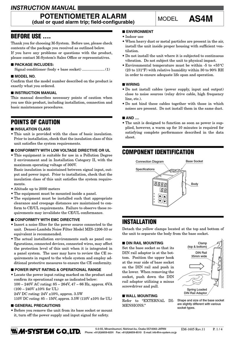
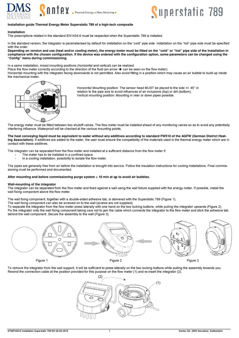
Gates FS 94 User manual

OPERATING MANUAL
TUBE END FORMING MACHINE
FS 94
GATES TUBE FITTINGS GMBH
MASCHINENANLEITUNG
MONTAGEMASCHINE
FS 94
GATES TUBE FITTINGS GMBH
MANUAL DE OPERACIÓN
MAQUINA DE FORMACIÓN DE TUBO
FS 94
GATES TUBE FITTINGS GMBH

2GATES.COM
TUBE END FORMING MACHINE FS 94
OPERATION MANUAL
CONTENTS PAGE
1. General information........................................... 4
2. Basic safety instructions.................................... 5
2.1 Obligations and liability............................... 5
2.2 Safety symbols ............................................ 5
2.3 Hazards when handling the machine ......... 5
2.4 Safety devices.............................................. 6
2.5 Intended use................................................ 6
2.6 Informal safety measures to be
performed by the operator................................. 6
2.7 Obligations of the operator/personnel....... 6
2.8 Training of personnel................................... 6
2.9 Workstation for the operating personnel.... 6
2.10 Hazards caused by electrical
and hydraulic energy.......................................... 6
2.11 Cleaning the machine ............................... 7
2.12 Structural changes to the assembly
machine FS 94................................................... 7
3. Transporting the assembly machine ................. 7
3.1 Transport...................................................... 7
3.2 Transport damages...................................... 7
4. Description of the assembly machine FS 94.... 8
4.1 Description................................................... 8
4.2 Overall view.................................................. 8
4.3 Operating and display elements ................. 8
4.4 Technical data ............................................. 9
4.5 Marking of the assembly machine FS 94... 9
5. Start-up............................................................. 10
5.1 Set-up......................................................... 10
5.2 Exchanging the screwed sealing plug....... 10
5.3 Tube quality................................................ 10
5.4 Tube machining ......................................... 10
5.5 Tool change................................................ 11
5.6 Operation ................................................... 12
Important instructions ..................................... 13
6. Shutdown, disposal.......................................... 14
6.1 Shutdown................................................... 14
6.2 Disposal ..................................................... 14
7. Maintenance .................................................... 15
7.1 Oil quality ................................................... 15
7.2 Oil change .................................................. 15
7.3 Cleaning the machine ............................... 15
7.4 Cleaning and care of the tools.................. 15
8. Inspection and maintenance list..................... 16
9. Error causes ..................................................... 17
10. Customer/aftersales service........................... 18
11. FS system ......................................................... 20
12. Machine and tools ........................................... 21
12.1. Technical data of machine..................... 21
12.2. Usable tube sizes – steel....................... 21
12.3. Usable tube sizes – high-grade steel
(1.4571) ........................................................... 22
MONTAGEMASCHINE FS 94
MASCHINENANLEITUNG
INHALTSVERZEICHNIS
1. Allgemeine Hinweise.......................................... 4
2. Grundlegende Sicherheitshinweise................... 5
2.1 Verpflichtung und Haftung........................... 5
2.2 Sicherheitssymbole .................................... 5
2.3 Gefahren im Umgang mit der Maschine..... 5
2.4 Sicherheitseinrichtungen ............................ 6
2.5 Bestimungsgemäße Verwendung ............... 6
2.6 Informelle Sicherheitsmaßnahmen
durch den Betreiber........................................... 6
2.7 Verpflichtung des Betreibers /
des Personals..................................................... 6
2.8 Ausbildung des Personals........................... 6
2.9 Arbeitsplatz für das Bedienungspersonal.... 6
2.10 Gefahren durch elektrische und
hydraulische Energie.......................................... 6
2.11 Reinigen der Montagemaschine............... 7
2.12 Bauliche Veränderungen an der
Montagemaschine FS 94................................... 7
3. Transport der Montagemaschine ...................... 7
3.1 Transport...................................................... 7
3.2 Transportschäden........................................ 7
4. Beschreibung der Montagemaschine FS 94..... 8
4.1 Beschreibung............................................... 8
4.2 Gesamtansicht ............................................ 8
4.3 Bedienungs- und Anzeigeelemente ............ 8
4.4 Technische Daten........................................ 9
4.5 Kennzeichnung der
Montagemaschine FS 94................................... 9
5. Inbetriebnahme................................................ 10
5.1 Aufstellung................................................. 10
5.2 Austausch der Verschlussschraube.......... 10
5.3 Rohrqualität ............................................... 10
5.4 Rohrbearbeitung........................................ 10
5.5 Werkzeugwechsel ...................................... 11
5.6 Bedienung.................................................. 12
Important instructions ..................................... 13
6. Außerbetriebnahme, Entsorgung .................... 14
6.1 Außerbetriebnahme................................... 14
6.2 Entsorgung................................................. 14
7. Wartung ............................................................ 15
7.1 Ölqualität ................................................... 15
7.2 Ölwechsel................................................... 15
7.3 Reinigung der Maschine............................ 15
7.4 Reinigung und Pflege der Werkzeuge ....... 15
8. Inspektions- und Wartungsliste....................... 16
9. ehlerursachen .................................................. 17
10. Kundendienst / Service................................... 18
11. FS system ......................................................... 20
12. Maschine und Werkzeuge................................ 21
12.1. Technische Daten Maschine.................. 21
12.2. Verwendbare Rohrgrößen Stahl............. 21
12.3. Verwendbare Rohrgrößen
Edelstahl (1.4571)........................................... 22
MAQUINA DE FORMACIÓN DE TUBO FS 94
MANUAL DE OPERACIONES
CONTENIDO
1. Información general........................................... 4
2. Instrucciones básicas de seguridad.................. 5
2.1 Obligaciones y responsabilidad .................. 5
2.2 Símbolos de seguridad ............................... 5
2.3 Peligros al manipular la máquina ............... 5
2.4 Dispositivos de seguridad ........................... 6
2.5 Uso previsto ................................................. 6
2.6 Medidas informales de seguridad
que debe adoptar el operador........................... 6
2.7 Obligaciones del operador/personal.......... 6
2.8 Capacitación del personal .......................... 6
2.9 Estación de trabajo para el
personal operativo ............................................. 6
2.10 Peligros causados por laenergía
eléctrica e hidráulica ......................................... 6
2.11 Limpieza de la máquina............................ 7
2.12 Cambios estructurales en la
máquina de montaje FS 94............................... 7
3. Transporte de la máquina de montaje.............. 7
3.1 Transporte.................................................... 7
3.2 Daños en el transporte................................ 7
4. Descripción de la máquina de
montaje FS 94 ................................................... 8
4.1 Descripción.................................................. 8
4.2 Vista general................................................ 8
4.3 Elementos de funcionamiento y
visualización....................................................... 8
4.4 Datos técnicos............................................. 9
4.5 Marcaje de la máquina de
montaje FS 94.................................................... 9
5. Empezar............................................................ 10
5.1 Configuración............................................. 10
5.2 Cambio del tapón de sellado atornillado.. 10
5.3 Calidad del tubo......................................... 10
5.4 Mecanizado de tubos................................ 10
5.5 Cambio de herramienta ............................ 11
5.6 Funcionamiento........................................ 12
Instrucciones importantes............................... 13
6. Cierre, eliminación ........................................... 14
6.1 Apagado..................................................... 14
6.2 Eliminación ................................................ 14
7. Mantenimiento................................................. 15
7.1 Calidad del aceite...................................... 15
7.2 Cambio de aceite....................................... 15
7.3 Limpieza de la máquina ............................ 15
7.4 Limpieza y cuidado de las herramientas.. 15
8. Lista de inspección y mantenimiento.............. 16
9. Causas de error................................................ 17
10. Servicio al cliente/postventa........................... 18
11. Sistema FS ....................................................... 20
12. Máquinas y herramientas................................ 21
12.1. Datos técnicos de la máquina ............... 21
12.2. Tamaños de tubo utilizables: Acero....... 21
12.3. Tamaños de tubo utilizables: Acero de alta
calidad (1.4571) .............................................. 22

3
GATES.COM
TUBE END FORMING MACHINE FS 94
OPERATION MANUAL
13. Tools.................................................................. 23
13.1. Clamping tools........................................ 23
13.2. Forming tools.......................................... 23
13.3. Tool list.................................................... 24
14. Accessories ...................................................... 25
14.1. Sealing and back-up rings – steel ......... 25
14.2. Sealing and back-up rings –
high-grade steel ............................................... 26
15. Forming............................................................. 27
15.1. Determining the tube length.................. 27
15.2. Sawing tubes .......................................... 27
15.3. Checking machine settings and tools ... 27
15.4. Sliding nut onto tube.............................. 27
15.5. Forming the tube.................................... 27
15.6. Inspecting the formed tube Visual
inspection......................................................... 28
16. Assembly with FSR ring in the fitting body...... 30
16.1. Pressing the FSR ring into the fitting
body .................................................................. 30
16.2. Pressing the tube against the 24°
inclination......................................................... 30
16.3. Tightening the nut finger-tight................ 30
16.4. Completing assembly............................. 30
17. Assembly with FSSR ring in the fitting body
(for thin tubes).................................................. 31
17.1. Sliding the FSSR ring onto the tube ...... 31
17.2 Pressing the tube into the 24°
connector ......................................................... 31
17.3. Tightening the nut finger-tight................ 31
17.3. Completing assembly............................. 31
18. Tube length shortening for steel...................... 32
19. Tube length shortening for high grade steel ... 33
20. Minimum straight tube length......................... 34
MONTAGEMASCHINE FS 94
MASCHINENANLEITUNG
13. Werkzeuge........................................................ 23
13.1. Spannwerkzeuge .................................... 23
13.2. Formwerkzeuge ...................................... 23
13.3. Werkzeugliste ......................................... 24
14. Zubehör ............................................................ 25
14.1. Dicht- und Stützringe Stahl.................... 25
14.2. Dicht- und Stützringe Edelstahl ............. 26
15. Umformung....................................................... 27
15.1. Rohrlänge ermitteln ............................... 27
15.2. Rohre absägen ....................................... 27
15.3. Maschineneinstellungen und
Werkzeuge prüfen ........................................... 27
15.4. Mutter auf Rohr schieben...................... 27
15.5. Rohr umformen ...................................... 27
15.6. Kontrolle des umgeformten Rohres
Sichtkontrolle ................................................... 28
16. Montage mit FSR - Ring im
Verschraubungskörper..................................... 30
16.1. FSR - Ring in Verschraubungskörper
eindrücken........................................................ 30
16.2. Rohr gegen 24° Schräge drücken......... 30
16.3. Mutter handfest anziehen ..................... 30
16.4. Fertigmontieren...................................... 30
17. Montage mit FSSR - Ring im
Verschraubungskörper (bei dünnen Rohren)..... 31
17.1. FSSR - Ring auf Rohr aufschieben ........ 31
17.2. Rohr in 24° - Stutzen drücken............... 31
17.3. Mutter handfest anzie............................ 31
17.3. Fertig montieren..................................... 31
18. Rohrlängenverkürzung für Stahl...................... 32
19. Rohrlängenverkürzung für Edelstahl ............... 33
20. Minimale gerade Rohrlänge ............................ 34
MAQUINA DE FORMACIÓN DE TUBO FS 94
MANUAL DE OPERACIONES
13. Herramientas ................................................... 23
13.1. Herramientas de sujeción...................... 23
13.2. Herramientas de formación................... 23
13.3. Lista de herramientas............................ 24
14. Accesorios ........................................................ 25
14.1. Anillos de sellado y respaldo de acero.. 25
14.2. Anillos de sellado y respaldo: Acero
de alta calidad.................................................. 26
15. Formado ........................................................... 27
15.1. Determinación de la longitud del tubo.. 27
15.2. Serrar tubos............................................ 27
15.3. Comprobación de ajustes y
herramientas de la máquina ........................... 27
15.4. Tuerca deslizante en el tubo.................. 27
15.5. Formando el tubo................................... 27
15.6. Inspección del tubo formado -
inspección visual.............................................. 28
16. Montaje con anillo fsr en el cuerpo del
accesorio.......................................................... 30
16.1. Presionar el anillo fsr en el cuerpo del
accesorio .......................................................... 30
16.2. Presionar el tubo contra la
inclinación de 24° ........................................... 30
16.3. Apriete la tuerca apretando el dedo...... 30
16.4. Finalización del montaje........................ 30
17. Montaje con anillo fssr en el cuerpo del
accesorio (para tubos delgados)..................... 31
17.1. Deslizamiento del anillo FSSR
sobre el tubo .................................................... 31
17.2 Presione el tubo en el conector
de 24°.............................................................. 31
17.3. Apriete la tuerca apretando el dedo...... 31
17.3. Finalización del montaje........................ 31
18. Acortamiento de longitud de tubo
para acero......................................................... 32
19. Acortamiento de longitud de tubo para
acero de alta calidad........................................ 33
20. Longitud mínima del tubo recto....................... 34

4GATES.COM
TUBE END FORMING MACHINE FS 94
OPERATION MANUAL
1. GENERAL INFORMATION
Identification data Type of machine
Model designation
Assembly machine
FS 94
Manufacturer address Company name
Street
Town
Telephone
Gates Tube Fittings GmbH
Kolumbusstrasse 54
D-53881 Euskirchen
0 22 51 / 12 56 - 0
Ordering of spare parts and customer service See address above
Document Version: 1.0
Date of creation: 04.02.2020
MONTAGEMASCHINE FS 94
MASCHINENANLEITUNG
1. ALLGEMEINE HINWEISE
Identifikation Maschinentyp
Modelbezeichnung
Seriennummer
Bestell Nummer
Baujahr
Montagemaschine
FS 94
FS 94
Kundeneintragung Inventar-Nr.
Standort
Herstelleranschrift Firmenname
Straße
Ort
Telefon
Gates Tube Fittings GmbH
Kolumbusstrasse 54
D-53881 Euskirchen
0 22 51 / 12 56 - 0
Ersatzteil-beschaffung und Kundendienst Anschrift wie oben
Dokument Version: 1.0
Date of creation: 04.02.2020
© Copyright 2021 - Gates Tube Fittings GmbH- technische Änderungen vorbehalten
MAQUINA DE FORMACIÓN DE TUBO FS 94
MANUAL DE OPERACIONES
1. INFORMACIÓN GENERAL
Datos de identificación Tipo de máquina
Designación del modelo
Máquina de montaje FS 94
Dirección del fabricante Razón social
Calle
Town
Teléfono
Kolumbusstrasse 54 D-53881
Euskirchen 0 22 51 / 12 56 - 0
Pedido de piezas de recambio y atención al cliente Ver dirección arriba
Documento Versión: 1.0 Fecha de
creación: 04.02.2020

5
GATES.COM
TUBE END FORMING MACHINE FS 94
OPERATION MANUAL
2. BASIC SAFETY INSTRUCTIONS
This operating manual contains important
instructions for operating the machine in a
safe manner.
2.1 OBLIGATIONS AND LIABILITY
Knowing the basic safety instructions and safety
regulations is a basic requirement for the safe
handling and smooth operation of this machine.
This operating manual, and in particular the safety
instructions contained in it, are to be complied
with by all persons who work on the machine.
In addition, the rules and regulations for accident
prevention that are applicable for the site of
operation are to be adhered to and the prescribed
inspection and maintenance work carried out.
Our general terms and conditions of sale and
delivery are generally applicable. These will be
made available to the operator no later than on
the date the contract is concluded. Guarantee
and liability claims for any personal injuries and
damage to property are excluded if they are
due to one or more of the following causes:
• The machine not being used in
accordance with its intended purpose
• Incorrect set-up, start-up, operation
and maintenance of the machine
• Operation of the machine with defective
safety devices or incorrectly attached
and non-functional safety devices
• Ignoring the instructions in this operating manual
• Unauthorised structural
modifications to the machine
• Poor monitoring of machine parts
that are subject to wear
• Improper performance of repairs
• Emergencies caused by external
influence or force majeure
2.2 SAFETY SYMBOLS
The following pages describe the safety instructions
and safety requirements.
Explanation of hazard and other symbols
In this operating manual, the following terms
and symbols are used to denote hazards and
instructions:
PROHIBITION SYMBOL
This prohibition symbol means that the activities or
things mentioned are to be strictly refrained from.
WARNING SYMBOL
This symbol means:
• An immediate and imminent danger to the
life and health of persons. Not adhering
to these instructions will result in severe
adverse health effects with the possibility of
lifethreatening injuries.
• A possible danger to the life and health of
persons. Not adhering to these instructions may
result in severe adverse health effects with the
possibility of lifethreatening injuries.
• A potentially dangerous situation. Not adhering to
these instructions may result in minor injuries or
damage to property.
2.3 HAZARDS WHEN HANDLING THE
MACHINE
The machine has been constructed in accordance
with state-of-the-art technology and the recognised
safety rules and regulations. Nevertheless, its
use may constitute a risk for the life and physical
condition of the user or of third parties, or cause
damage to the machine and to other property.
The machine must only be used
• For its intended purpose,
• In perfect working order with regard to safety.
Any malfunctions which may compromise safety
are to be immediately eliminated or reported to the
manufacturer.
MONTAGEMASCHINE FS 94
MASCHINENANLEITUNG
2. GRUNDLEGENDE
SICHERHEITSHINWEISE
Diese Betriebsanleitung enthält wichtige Hinweise,
um die Maschine sicherheitsgerecht zu bedienen.
2.1 VERPFLICHTUNG UND HAFTUNG
Grundvoraussetzung für den sicherheitsgerechten
Umgang und den störungsfreien Betrieb
dieser Maschine ist die Kenntnis der
grundlegenden Sicherheitshinweise
und der Sicherheitsvorschriften.
Diese Betriebsanleitung, insbesondere die
Sicherheitshinweise, sind von allen Personen
zu beachten, die an der Maschine arbeiten.
Darüber hinaus sind die für den Einsatzort
geltenden Regeln und Vorschriften zur
Unfallverhütung und die Einhaltung der
Inspektions- und Wartungsarbeiten zu beachten.
Grundsätzlich gelten unsere allgemeinen
Verkaufs- und Lieferbedingungen. Diese
stehen dem Betreiber spätestens seit
Vertragsabschlus zur Verfügung. Gewährleistungs-
und Haftungsansprüche bei Personen- und
Sachschäden sind ausgeschlossen, wenn
sie auf eine oder mehrere der folgenden
Ursachen zurückzuführen sind:
• Nicht bestimmungsgemäße Verwendung
der Maschine unsachgemäßes
Aufstellen, Inbetriebnehmen, Bedienen
und Warten der Maschine
• Betreiben der Maschine bei defekten
Sicherheitseinrichtungen oder nicht
ordnungsgemäß angebrachten, nicht
funktionsfähigen Sicherheitseinrichtungen
• Nichtbeachtung dieser Hinweise in der
Betriebsanleitung eigenmächtige bauliche
Veränderungen an der Maschine
• Mangelhafte Überwachung von Maschinenteilen,
die einem Verschleiß unterliegen
• Unsachgemäß durchgeführte Reparaturen
• Katastrophenfälle durch
Fremdkörpereinwirkung und höhere Gewalt
2.2 SICHERHEITSSYMBOLE
Die nachfolgenden Seiten beschreiben die
Sicherheitshinweise und Sicherheitsanforderungen.
Erklärungen der Gefahren- und Hinweissymbole
In dieser Betriebsanleitung werden folgende
Benennungen und Zeichen für Gefährdungen und
Hinweise verwendet:
VERBOTSZEICHEN
Dieses Verbotszeichen bedeutet, dass die
genannten Tätigkeiten bzw. Dinge unbedingt zu
unterlassen sind.
WARNZEICHEN
Dieses Symbol bedeutet:
• Eine unmittelbar drohende Gefahr für das Leben
und die Gesundheit von Personen.
Das Nichtbeachten dieser Hinweise hat schwere
gesundheitsschädliche Auswirkungen zur Folge bis
hin zu lebensgefährlichen Verletzungen.
• Eine möglicherweise drohende Gefahr für das
Leben und die Gesundheit von Personen.
Das Nichtbeachten dieser Hinweise kann schwere
gesundheitsschädliche Auswirkungen zur Folge
haben, bis hin zu lebensgefährlichen Verletzungen.
• Eine möglicherweise gefährliche Situation.
Das Nichtbeachten dieser Hinweise kann
leichte Verletzungen zur Folge haben oder zu
Sachbeschädigungen führen.
2.3 GEFAHREN IM UMGANG MIT DER
MASCHINE
Die Maschine ist nach dem Stand der Technik und
den anerkannten, sicherheitstechnischen Regeln
gebaut. Dennoch können bei ihrer Verwendung
Gefahren für Leib und Leben des Benutzers oder
Dritter bzw. Beeinträchtigungen an der Maschine
oder an anderen Sachwerten entstehen.
Die Maschine ist nur zu benutzen
• Ür die bestimmungsgemäße Verwendung,
• In sicherheitstechnisch einwandfreiem Zustand.
Störungen, die die Sicherheit beeinträchtigen
können, sind umgehend zu beseitigen
oder dem Hersteller zu melden.
MAQUINA DE FORMACIÓN DE TUBO FS 94
MANUAL DE OPERACIONES
2. INSTRUCCIONES BÁSICAS DE
SEGURIDAD
Este manual contiene instrucciones importantes
para operar la máquina de manera segura.
2.1 OBLIGACIONES Y RESPONSABILIDAD
Conocer las instrucciones básicas de
seguridad y las normas de seguridad es un
requisito básico para el manejo seguro y el
buen funcionamiento de esta máquina.
Este manual de instrucciones, y en particular
las instrucciones de seguridad contenidas
en él, deben ser cumplidas por todas las
personas que trabajan en la máquina.
Además, se respetarán las normas y reglamentos
de prevención de accidentes aplicables al lugar
de operación y se llevarán a cabo las labores
de inspección y mantenimiento prescritas.
Nuestros términos y condiciones generales de
venta y entrega son generalmente aplicables.
Estos se pondrán a disposición del operador
a más tardar en la fecha de celebración del
contrato. Se excluyen las reclamaciones
de garantía y responsabilidad por lesiones
personales y daños a la propiedad si se deben
a una o más de las siguientes causas:
• La máquina no se utiliza de acuerdo
con su propósito previsto
• Instalación, puesta en marcha, funcionamiento
y mantenimiento incorrectos de la máquina
• Manejo de la máquina con dispositivos
de seguridad defectuosos o dispositivos
de seguridad incorrectamente
conectados y no funcionales
• Ignorar las instrucciones de este manual
• Modificaciones estructurales no
autorizadas de la máquina
• Supervisión deficiente de las piezas de la
máquina que están sujetas a desgaste
• Realización incorrecta de las reparaciones
• Emergencias causadas por influencia
externa o fuerza mayor
2.2 SÍMBOLOS DE SEGURIDAD
Las siguientes páginas describen las instrucciones
de seguridad y los requisitos de seguridad.
Explicación del peligro y otros símbolos
En este manual de instrucciones, se utilizan los
siguientes términos y símbolos para indicar peligros
e instrucciones:
SÍMBOLO DE PROHIBICIÓN
Este símbolo de prohibición significa que las
actividades o cosas mencionadas deben abstenerse
estrictamente.
SÍMBOLO DE ADVERTENCIA
Este símbolo significa:
• Un peligro inmediato e inminente para la vida y la
salud de las personas. El incumplimiento de estas
instrucciones resultará en graves efectos adversos
para la salud con la posibilidad de lesiones
potencialmente mortales.
• Un posible peligro para la vida y la salud de
las personas. El incumplimiento de estas
instrucciones puede resultar en efectos adversos
severos para la salud con la posibilidad de
lesiones potencialmente mortales.
• Una situación potencialmente peligrosa. El
incumplimiento de estas instrucciones puede
resultar en lesiones menores o daños a
la propiedad.
2.3 PELIGROS AL MANIPULAR LA
MÁQUINA
La máquina ha sido construida de acuerdo
con la tecnología más avanzada y las normas y
reglamentos de seguridad reconocidos. No obstante,
su uso puede constituir un riesgo para la vida y el
estado físico del usuario o de terceros, o causar
daños a la máquina y a otros bienes.
La máquina solo debe utilizarse
• Para su propósito previsto,
• En perfecto estado de funcionamiento
con respecto a la seguridad.
Cualquier mal funcionamiento que pueda
comprometer la seguridad debe eliminarse
inmediatamente o notificarse al fabricante.

6GATES.COM
TUBE END FORMING MACHINE FS 94
OPERATION MANUAL
2.4 SAFETY DEVICES
The assembly machine FS 94 has the following
safety devices
Emergency stop switch
Bell with sensor and warning
Pressure limitation valve
Housing cover
Two-hand control
Before starting up the assembly machine,
all safety devices must always be
properly attached and functional.
Safety devices may be only removed
• After shutdown and
• Once the power supply plug has been pulled out.
All safety devices are to be checked on a
regular basis.
2.5 INTENDED USE
The machine may only be used for forming
contours on hydraulic tubes. The tubes approved
are steel tubes (E235+N, E355+N) in accordance
with DIN EN 10305-4 and high-grade steel tubes
(1.4571) in accordance with DIN 10216-5, min.
tolerances D4/T3.
2.6 INFORMAL SAFETY MEASURES TO BE
PERFORMED BY THE OPERATOR
The operating manual must always be kept
on the site where the machine is used.
In addition to the operating manual, the generally
applicable and local regulations for accident
prevention and environmental protection are
to be made available and complied with.
All notices affixed to the machine
must be kept legible.
2.7 OBLIGATIONS OF THE OPERATOR/
PERSONNEL
The operator/personnel commit themselves to only
allowing persons to work on the machine who
Are familiar with the fundamental regulations
on occupational health and safety and
accident prevention and have been instructed
regarding the handling of the machine.
Have read and understood the operating manual
read and/or have been introduced to the
machine, and confirmed with their signature.
2.8 TRAINING OF PERSONNEL
Only trained and instructed personnel
may work on the machine.
The responsibilities of personnel are to be
clearly specified for the putting out, selecting
and inserting of tools, for start-up, for operation
and for the performance of inspection and
maintenance work on the machine.
Trainee personnel may only work on the machine
when supervised by an experienced person.
2.9 WORKSTATION FOR THE OPERATING
PERSONNEL
The work area is located in front of the machine.
The workstation is to be kept clean and tidy
near and around the machine and regular
checks must be made to ensure this.
2.10 HAZARDS CAUSED BY ELECTRICAL
AND HYDRAULIC ENERGY
Work may only be carried out on the
electrical and hydraulic power supply
by a trained member of staff.
MONTAGEMASCHINE FS 94
MASCHINENANLEITUNG
2.4 SICHERHEITSEINRICHTUNGEN
Die Montagemaschine FS 94 verfügt über folgende
Sicherheitseinrichtungen
Not-Aus-Schalter
Glocke mit Sensor und Warnhinweis
Druckbegrenzungsventil
Gehäuseabdeckung
Zweihandbedienung
Vor jeder Inbetriebnahme der Montagemaschine
müssen alle Sicherheitseinrichtungen sachgerecht
angebracht und funktionsfähig sein.
Sicherheitseinrichtungen dürfen
nur entfernt werden
• Nach Stillstand und
• Nach Ziehen des Netzsteckers.
Alle vorhandenen Sicherheitseinrichtungen sind
regelmäßig zu überprüfen.
2.5 BESTIMUNGSGEMÄSSE VERWENDUNG
Die Maschine darf nur zum Anformen einer Kontur
an Hydraulikrohre verwendet werden. Zugelassen
sind Stahlrohre (E235+N, E355+N)nach DIN EN
10305-4 bzw. Edelstahlrohre (1.4571) nach DIN
10216-5, Toleranzen min. D4/T3.
2.6 INFORMELLE
SICHERHEITSMASSNAHMEN DURCH DEN
BETREIBER
Die Betriebsanleitung ist ständig am
Einsatzort der Maschine aufzubewahren.
Ergänzend zur Betriebsanleitung sind die
allgemein gültigen sowie die örtlichen
Regelungen zur Unfallverhütung und zum
Umweltschutz bereitzustellen und zu beachten.
Alle Hinweise an der Maschine sind
in lesbarem Zustand zu halten.
2.7 VERPFLICHTUNG DES BETREIBERS /
DES PERSONALS
Der Betreiber/ das Personal verpflichtet sich, nur
Personen an der Maschine arbeiten zu lassen, die
Mit den grundlegenden Vorschriften über
Arbeitssicherheit und Unfallverhütung
vertraut und in die Handhabung der
Maschine eingewiesen sind.
Die Betriebsanleitung gelesen bzw. an der
Maschineneinführung teilgenommen, verstanden
und durch ihre Unterschrift bestätigt haben.
2.8 AUSBILDUNG DES PERSONALS
Nur geschultes und eingewiesenes Personal
darf an der Maschine arbeiten.
Die Zuständigkeiten des Personals sind
klar festzulegen für das Ausstellen,
Auswählen und Einsetzen der Werkzeuge,
Inbetriebnehmen, Bedienen und für
die Durchführung von Inspektions- und
Wartungsarbeiten an der Maschine.
Anzulernendes Personal darf nur unter Aufsicht
einer erfahrenen Person an der Maschine arbeiten.
2.9 ARBEITSPLATZ FÜR DAS
BEDIENUNGSPERSONAL
Der Arbeitsbereich befindet sich vor der Maschine.
Die Sauberkeit und Übersichtlichkeit
des Arbeitsplatzes an und um die
Maschine ist zu gewährleisten und durch
regelmäßige Kontrollen zu prüfen.
2.10 GEFAHREN DURCH ELEKTRISCHE UND
HYDRAULISCHE ENERGIE
Arbeiten an der elektrischen und der
hydraulischen Versorgung sind nur von
einer geschulten Kraft auszuführen.
MAQUINA DE FORMACIÓN DE TUBO FS 94
MANUAL DE OPERACIONES
2.4 DISPOSITIVOS DE SEGURIDAD
La máquina de montaje FS 94 dispone de los
siguientes dispositivos de seguridad
Interruptor de parada de emergencia
Campana con sensor y advertencia
Válvula de limitación de presión
Cubierta del compartimiento
Control a dos manos
Antes de poner en marcha la máquina, todos los
dispositivos de seguridad deben estar siempre
correctamente conectados y funcionales.
Los dispositivos de seguridad
solo pueden retirarse
• Después del apagado y
• Una vez que se haya sacado el enchufe
de la fuente de alimentación.
Todos los dispositivos de seguridad deben
controlarse periódicamente.
2.5 USO PREVISTO
La máquina solo puede utilizarse para formar
contornos en tubos hidráulicos. Los tubos
homologados son tubos de acero (E235+N,
E355+N) según DIN EN 10305-4 y tubos de acero
de alta calidad (1.4571) según DIN 10216-5,
tolerancias mínimas D4/T3.
2.6 MEDIDAS INFORMALES DE SEGURIDAD
QUE DEBE ADOPTAR EL OPERADOR
El manual de instrucciones debe mantenerse
siempre en el lugar donde se utiliza la máquina.
Además del manual de funcionamiento,
se pondrán a disposición y cumplirán las
normas generales y locales de prevención de
accidentes y protección del medio ambiente.
Todos los avisos colocados en la máquina
deben mantenerse legibles.
2.7 OBLIGACIONES DEL OPERADOR/
PERSONAL
El operador/personal se compromete a permitir
únicamente trabajar en la máquina a personas que
Están familiarizados con las normas
fundamentales sobre salud y seguridad
en el trabajo y prevención de accidentes
y han recibido instrucciones sobre la
manipulación de la máquina.
Haber leído y comprendido el manual de
instrucciones leído y/o introducido en la
máquina, y confirmado con su firma.
2.8 CAPACITACIÓN DEL PERSONAL
Solo personal capacitado e instruido
puede trabajar en la máquina.
Las responsabilidades del personal se
especificarán claramente para la colocación,
selección e inserción de herramientas, para
el arranque, para el funcionamiento y para
la realización de trabajos de inspección
y mantenimiento en la máquina.
El personal en prácticas solo puede trabajar
en la máquina cuando está supervisado
por una persona experimentada.
2.9 ESTACIÓN DE TRABAJO PARA EL
PERSONAL OPERATIVO
El área de trabajo se encuentra
frente a la máquina.
La estación de trabajo debe mantenerse
limpia y ordenada cerca y alrededor de la
máquina y deben realizarse comprobaciones
periódicas para garantizarlo.
2.10 PELIGROS CAUSADOS POR LA
ENERGÍA ELÉCTRICA E HIDRÁULICA
Los trabajos relativos al suministro de
energía eléctrica e hidráulica sólo podrán
ser realizados por un agente cualificado.

7
GATES.COM
TUBE END FORMING MACHINE FS 94
OPERATION MANUAL
2.11 CLEANING THE MACHINE
Used substances and materials should be correctly
handled and disposed of, in particular
When working on the hydraulics and
When cleaning with solvents.
2.12 STRUCTURAL CHANGES TO THE
ASSEMBLY MACHINE FS 94
It is forbidden to make any changes, fittings
or modifications to the machine without the
manufacturer's consent. Machine parts that are
not in perfect working order are to be exchanged
immediately.
Only original spare and wear parts are to be used.
Spare parts from elsewhere cannot be guaranteed
to have been designed and manufactured in such
a way as to fulfil the operational stress and safety
requirements.
3. TRANSPORTING THE ASSEMBLY
MACHINE
3.1 TRANSPORT
The machine is only intended for transport using
forklifts and industrial trucks. The machine can be
lifted and transported using the forks beneath the
frame. Observe the relevant regulations.
3.2 TRANSPORT DAMAGES
Any transport damages determined must
be noted on the shipping documents.
The responsible supplier (normally the truck
driver) must confirm the determined damage on
the shipping documents by affixing his signature.
Transport damages are to be reported to
the manufacturer as soon as possible.
MONTAGEMASCHINE FS 94
MASCHINENANLEITUNG
2.11 REINIGEN DER MONTAGEMASCHINE
Verwendete Stoffe und Materialien sind sachgerecht
zu handhaben und zu entsorgen, insbesondere
Bei Arbeiten an der Hydraulik und
Beim Reinigen mit Lösungsmitteln.
2.12 BAULICHE VERÄNDERUNGEN AN DER
MONTAGEMASCHINE FS 94
Ohne Genehmigung des Herstellers sind
Veränderungen, An- oder Umbauten der
Maschine untersagt.
Maschinenteile in nicht einwandfreiem Zustand sind
sofort auszutauschen.
Nur Original Ersatz – und Verschleißteile sind
zu verwenden.
Bei nicht Original Ersatzteilen ist nicht gewährleistet,
dass sie beanspruchungs- und sicherheitsgerecht
konstruiert und gefertigt sind.
3. TRANSPORT DER
MONTAGEMASCHINE
3.1 TRANSPORT
Die Maschine ist nur für den Transport mit
Gabelstapler und Flurförderfahrzeugen vorgesehen.
Die Ma-schine kann mit den Gabeln unterhalb des
Rahmens angehoben und transportiert werden.
Beachten Sie die entsprechenden Vorschriften.
3.2 TRANSPORTSCHÄDEN
Festgestellte Transportschäden müssen auf
den Frachtpapieren festgehalten werden.
Der verantwortliche Zulieferer (im Normalfall
der LKW-Fahrer) muss die festgestellten
Schäden auf den Frachtpapieren durch
seine Unterschrift bestätigen.
Transportschäden sind so schnell wie
möglich dem Hersteller zu melden.
MAQUINA DE FORMACIÓN DE TUBO FS 94
MANUAL DE OPERACIONES
2.11 LIMPIEZA DE LA MÁQUINA
Las sustancias y materiales usados deben
manipularse y eliminarse correctamente,
en particular
Cuando se trabaja en la hidráulica y
Al limpiar con disolventes.
2.12 CAMBIOS ESTRUCTURALES EN LA
MÁQUINA DE MONTAJE FS 94
Queda prohibido realizar cambios, accesorios o
modificaciones en la máquina sin el consentimiento
del fabricante. Las piezas de la máquina que no
estén en perfecto estado de funcionamiento deben
cambiarse inmediatamente.
Solo se utilizarán piezas de repuesto y de desgaste
originales.
No puede garantizarse que las piezas de repuesto
de otros lugares hayan sido diseñadas y fabricadas
de tal manera que cumplan los requisitos de tensión
operativa y seguridad.
3. TRANSPORTE DE LA MÁQUINA
DE MONTAJE
3.1 TRANSPORTE
La máquina solo está destinada al transporte con
carretillas elevadoras y carretillas industriales. La
máquina se puede levantar y transportar utilizando
las horquillas debajo del cuadro. Observar las
normas pertinentes.
3.2 DAÑOS EN EL TRANSPORTE
Cualquier daño durante el transporte debe
anotarse en los documentos de envío.
El proveedor responsable (normalmente
el conductor del camión) debe confirmar
el daño determinado en los documentos
de envío colocando su firma.
Los daños en el transporte deben notificarse
al fabricante lo antes posible.

8GATES.COM
TUBE END FORMING MACHINE FS 94
OPERATION MANUAL
4. DESCRIPTION OF THE
ASSEMBLY MACHINE FS 94
4.1 DESCRIPTION
The machine is intended exclusively for
manufacturing the Gates-FSTM form on hydraulic
tubes sized 6-42 mm, for material see point 5.3.
The machine may only be used for the intended
operating conditions. The intended use
also includes:
The observance of all instructions
in the operating manual
The performance of prescribed
inspection and maintenance work.
Malfunction lamp
Emergency
stop switch
Plug for
network
cable
Main switch
Connection for
foot switch
Ready indicator
Emergency
stop switch
Reset button
Start button
4.2 OVERALL VIEW
4.3 OPERATING AND DISPLAY ELEMENTS
MONTAGEMASCHINE FS 94
MASCHINENANLEITUNG
4. BESCHREIBUNG DER
MONTAGEMASCHINE FS 94
4.1 BESCHREIBUNG
Die Maschine dient ausschließlich der Herstellung
der Gates-FSTM Form an Hydraulikrohren der Größe
6-42 mm, Material siehe Punkt 5.3.
Die Maschine darf nur für die vorgesehenen
Betriebsbedingungen eingesetzt werden.
Zur bestimmungsgemäßen Verwendung gehört auch:
Das Beachten aller Hinweise aus
der Bedienungsanleitung
Und die Einhaltung der Inspektions-
und Wartungsarbeiten.
Lampe Störung
Notaus-
Schalter
Plug for
network cable
Hauptschalter
Anschluss
Fussschalter
Anzeige
Betriebsbereit
Reset-Taste
Start-Taste
4.2 GESAMTANSICHT
4.3 BEDIENUNGS- UND ANZEIGEELEMENTE
MAQUINA DE FORMACIÓN DE TUBO FS 94
MANUAL DE OPERACIONES
4. DESCRIPCIÓN DE LA MÁQUINA
DE MONTAJE FS 94
4.1 DESCRIPCIÓN
La máquina está destinada exclusivamente a
la fabricación de la forma Gates-FS en tubos
hidráulicos de tamaño 6-42 mm, para el material
véase el punto 5.3.
La máquina solo puede utilizarse en las condiciones
de funcionamiento previstas. El uso previsto
también incluye:
La observancia de todas las instrucciones
del manual de instrucciones
La realización de los trabajos de inspección
y mantenimiento prescritos.
4.2 VISTA GENERAL
4.3 ELEMENTOS DE FUNCIONAMIENTO Y
VISUALIZACIÓN
Indicador de mal
funcionamiento
Interruptor
de parada de
emergencia
Enchufe para
cable de red
Interruptor principal
Conexión para
interruptor de pie
Indicador listo
Interruptor
de parada de
emergencia
Botón de reset
Botón Inicio

9
GATES.COM
TUBE END FORMING MACHINE FS 94
OPERATION MANUAL
4.4 TECHNICAL DATA
4.4.1 General data
Width 740 mm
Depth 860 mm
Height 350 mm
Weight 195 kg
(without tools)
4.4.2 Power supply
Voltage 400 V
Fuse protection 16 A
Operating pressure 600 bar max.
Power 3.5 kW
Voltage supply in accordance with IEC 60038
is required, since machine will not function
correctly otherwise.
4.4.3 Ambient conditions
Min. ambient temperature +5°C
Max. ambient temperature +35°C
Max. relative humidity 80%
If the machine is to be put into storage for more
than 6 months (for sea transit for example), please
consult the manufacturer. The machine must be
specially protected in this case.
4.4.4 Hydraulic oil
Oil type HLP 46
Oil quantity approx. 7 L
4.4.5 Noise level
Noise level ≤ 72 dB(A)
4.5 MARKING OF THE ASSEMBLY MACHINE
FS 94
The type plate and the CE marking can be found on
the front side of the machine.
MONTAGEMASCHINE FS 94
MASCHINENANLEITUNG
4.4 TECHNISCHE DATEN
4.4.1 Allgemeine Daten
Breite 740 mm
Tiefe 860 mm
Höhe 350 mm
Gewicht 195 kg
(ohne Werkzeuge)
4.4.2 Energieversorgung
Spannung 400 V
Absicherung 16 A
Betriebsdruck max. 600 bar
Leistung 3.5 kW
Spannungsversorgung muß gemäß IEC 60038
gegeben sein, da Maschine ansonsten nicht korrekt
funktioniert.
4.4.3 Umgebungsbedingungen
min. Umgebungstemperatur +5°C
max. Umgebungstemperatur +35°C
max. relative Luftfeuchte 80%
Bei Einlagerung von mehr als 6 Monaten, (z.B.
während Seetransport) halten Sie Rücksprache mit
dem Hersteller. Die Maschine muss in diesem Fall
besonders geschützt werden.
4.4.4 Hydrauliköl
Ölsorte HLP 46
Ölmenge ca. L
4.4.5 Geräuschpegel
Geräuschpegel ≤ 72 dB(A)
4.5 KENNZEICHNUNG DER
MONTAGEMASCHINE FS 94
Das Typenschild sowie die CE-Kennzeichnung
befinden sich auf der Vorderseite der Maschine.
MAQUINA DE FORMACIÓN DE TUBO FS 94
MANUAL DE OPERACIONES
4.4 DATOS TÉCNICOS
4.4.1 Datos generales
Anchura 740mm
Profundidad 860mm
Altura 350 mm
Peso 195 kg (sin
herramientas)
4.4.2 Fuente de alimentación
Voltaje 400 V
Protección de espoletas 16 A
Presión de funcionamiento 600 bar máx.
Potencia 3.5kW
El suministro de tensión de acuerdo con IEC 60038
es necesario, ya que la máquina no funcionará
correctamente de lo contrario.
4.4.3 Condiciones ambientales
Temperatura ambiental mínima +5°C
Temperatura ambiental máxima +35°C
Humedad relativa máxima 80%
Si la máquina se va a almacenar durante más de 6
meses (por ejemplo, para el transporte marítimo),
consulte al fabricante. La máquina debe estar
especialmente protegida en este caso.
4.4.4 Aceite hidráulico
Tipo de aceite HLP 46
Cantidad de aceite aprox. 7 L
4.4.5 Nivel de ruido
Nivel de ruido ≤ 72 dB(A)
4.5 MARCAJE DE LA MÁQUINA DE
MONTAJE FS 94
La placa de tipo y el marcaje CE se encuentran en la
parte delantera de la máquina.

10 GATES.COM
TUBE END FORMING MACHINE FS 94
OPERATION MANUAL
5. START-UP
5.1 SET-UP
The ground on which the machine is to be set up
must be adequate to bear the weight of the machine
and ensure its stability.
The assembly machine FS 94 is ready for operation:
Once the sealing plug has been exchanged
for the vent screw/ see point 5.2,
Once the machine has been properly
connected to the power supply 400 V/ 16 A,
Once the tool has been selected and inserted,
Once the bell has been closed
After the direction of rotation has been verified
IMPORTANT
The machine is to be protected against weathering.
IMPORTANT
When working on the electrics, mechanics and
hydraulics, the machine is to be shut off from the
electricity supply.
5.2 EXCHANGING THE SCREWED SEALING
PLUG
For transporting the machine, the tank is sealed with
a screwed sealing plug for reasons of safety.
For start-up, it is necessary to remove the screwed
sealing plug and to exchange it for the enclosed
ventilation connector.
To do so, remove the cover from the machine and
the screwed sealing plug. Now insert the ventilation
connector and fasten it finger-tight.
Keep the screwed sealing plug (VSCH) for possible
transportation.
IMPORTANT
For transporting the machine, the tank must be
sealed with a screwed sealing plug.
For operating the machine, the screwed sealing plug
must be exchanged for a ventilation connector.
5.3 TUBE QUALITY
Seamless, cold-bending and flangeable
tube materials in accordance with EN
10305-4 (EN235+N, EN355+N) or high-
grade steel tubes (1.4571) in accordance
with DIN 10216-5 are to be used.
The tube tolerances for high-grade steel tubes
(1.4571) must correspond to at least D4/
T3 for the outside and inside diameter.
A perfect condition of tube is to be used, and
the tube must show no signs of damage.
5.4 TUBE MACHINING
The tube ends
Must be deburred on the inside and
outside, chamfer of 0.2x45° maximum
Are to sawn off at right angles, without
using a tube cutter or cut-off wheel
Must be cleaned in the clamping and
deformation area and freed from paint,
grease, oil, dust and impurities.
MONTAGEMASCHINE FS 94
MASCHINENANLEITUNG
5. INBETRIEBNAHME
5.1 AUFSTELLUNG
Der Boden zur Aufstellung der Maschine muß
so beschaffen sein, dass das Maschinengewicht
aufge-nommen werden kann und ein sicherer Stand
gewährleistet ist.
Die Montagemaschine FS 94 ist,
Nach Auswechseln des
Verschlußstopfens gegen die
Entlüftungsschraube/ siehe Punkt 5.2,
Nach ordnungsgemäßen Anschluss an
die Netzversorgung 400 V/ 16 A, ∫ nach
Auswahl und Einsetzen des Werkzeuges,
Schließen der Glocke
Und nach Prüfung der Drehrichtung
ACHTUNG
Die Maschine ist vor Witterungseinflüssen
zu schützen.
ACHTUNG
Bei Arbeiten an der Elektrik, Mechanik und der
Hydraulik ist die Maschine von der Stromversorgung
zu trennen.
5.2 AUSTAUSCH DER
VERSCHLUSSSCHRAUBE
Für den Transport der Maschine ist der Tank aus
Sicherheitsgründen mit einer Verschlussschraube
ver-schlossen.
Für die Inbetriebnahme ist es notwendig, die
Verschlussschraube zu entfernen und gegen
den beiliegen-den Be- und Entlüftungsstutzen
auszutauschen.
Entfernen Sie dazu den Deckel auf der Maschine
und die Verschlussschraube. Setzen Sie nun den
Ein-füllstutzen ein und ziehen Sie ihn handfest an.
Verwahren Sie die Verschlussschraube (VSCH) für
eventuelle Transporte auf.
ACHTUNG
Für den Transport der Maschine muss der Tank mit
einer Verschlussschraube verschlossen werden.
Für das Betreiben der Maschine muss die
Verschlussschraube gegen einen Be- und
Entlüftungsstutzen ausgetauscht werden.
5.3 ROHRQUALITÄT
Es sind nahtlose kaltbiege- und bördelfähige
Rohrwerkstoffe nach EN 10305-4 (EN235+N,
EN355+N) bzw. Edelstahlrohre (1.4571)
nach DIN 10216-5 zu verwenden.
Die Rohrtoleranzen für Edelstahlrohre
(1.4571) müssen für den Aussen- und
Innendurchmesser min. D4/T3 entsprechen.
Es ist eine einwandfreie Rohrbeschaffenheit
zu verwenden, wobei das Rohr keine
Beschädigungen aufweisen darf.
5.4 ROHRBEARBEITUNG
Die Rohrenden
Müssen innen und Aussen entgratet
sein, Kantenbruch maximal 0,2x45°
Sind rechtwinklig abzusägen, keine
Rohrschneider oder Trennscheiben verwenden
Müssen im Spann- und Verformungsbereich
gesäubert und frei von Farbe, Fett, Öl,
Staub und Verunreinigungen sein.
MAQUINA DE FORMACIÓN DE TUBO FS 94
MANUAL DE OPERACIONES
5. EMPEZAR
5.1 CONFIGURACIÓN
El suelo sobre el que se instale la máquina deberá
ser adecuado para soportar el peso de la misma y
garantizar su estabilidad.
La máquina de montaje FS 94 está lista
para funcionar:
Una vez cambiado el tapón de sellado por el
tornillo de ventilación/véase el punto 5.2,
Una vez que la máquina se ha
conectado correctamente a la fuente
de alimentación 400 V/ 16 A,
Una vez seleccionada e insertada la herramienta,
Una vez cerrada la campana
Después de verificar el sentido de rotación
IMPORTANTE
La máquina debe estar protegida contra la
intemperie.
IMPORTANTE
Cuando se trabaja con electricidad, mecánica
e hidráulica, la máquina debe apagarse del
suministro eléctrico.
5.2 CAMBIO DEL TAPÓN DE SELLADO
ATORNILLADO
Para transportar la máquina, el depósito se sella
con un tapón de sellado roscado por razones
de seguridad.
Para el arranque, es necesario quitar el tapón de
sellado atornillado y cambiarlo por el conector de
ventilación cerrado.
Para ello, retire la tapa de la máquina y el tapón
de sellado atornillado. Ahora inserte el conector de
ventilación y sujételo con los dedos apretados.
Mantenga el tapón de sellado atornillado (VSCH)
para su posible transporte.
IMPORTANTE
Para transportar la máquina, el depósito debe
sellarse con un tapón de sellado atornillado.
Para operar la máquina, el tapón de sellado roscado
debe cambiarse por un conector de ventilación.
5.3 CALIDAD DEL TUBO
Se utilizarán materiales tubulares sin
costuras, doblables en frío y embridables
de acuerdo con EN 10305-4 (EN235+N,
EN355+N) o tubos de acero de alta calidad
(1.4571) de acuerdo con DIN 10216-5.
Las tolerancias de los tubos de acero de alta
calidad (1.4571) deben corresponder al menos
a D4/T3 para el diámetro exterior e interior.
Se debe usar un tubo en perfecto estado, y
el tubo no debe mostrar signos de daño.
5.4 MECANIZADO DE TUBOS
El tubo termina
Debe desbarbarse por dentro y por
fuera, chaflán de 0,2x45° máximo
Son para serrar en ángulo recto, sin utilizar
un cortador de tubo o rueda de corte
Debe limpiarse en el área de sujeción
y deformación y liberarse de pintura,
grasa, aceite, polvo e impurezas.

11
GATES.COM
TUBE END FORMING MACHINE FS 94
OPERATION MANUAL
5.5 TOOL CHANGE
FOW SPW92
1. Tools must be available for start-up.
2. Push back the tool flap.
3. Before inserting the tools it must be made sure that they
are free from shavings and impurities.
4. Worn or defective tools are to be exchanged immediately.
5. Forming connectors are to be inserted as shown in the
picture. (bayonet fixing)
6. Clamping jaws are to be inserted as shown in the picture.
The running surface of the tool flap must always be
slightly greased. After inserting, press the start button.
7. Close the tool flap.
IMPORTANT
Make sure that the tools fit the desired tube size.
MONTAGEMASCHINE FS 94
MASCHINENANLEITUNG
5.5 WERKZEUGWECHSEL
FOW SPW92 1. Zur Inbetriebnahme müssen Werkz veuge orhanden sein.
2. Werkzeugklappe zurückschieben.
3. Vor dem Einsetzen Wdes erkzeuges ist darauf zu achten,
dass diese vfrei on Spänen Vund erunreinigungen ist.
4. Verschlissene oder defekt We erkzeuge sind umgehend
austauschen.
5. Umformstutzen sind wie im Bild einzu setzen.
(Bajonettverschluß)
6. Spannbacken sind wie im Bild einzu etzen.
Die auffläche Wder erkzeug klappe muß immer
leicht eingefettet sein. Nach dem Einlegen die
Starttaste drücken.
7. Werkzeugklappe schließen.
ACHTUNG
Achten Sie darauf, das die Werkzeuge zur gewünschten Rohrgröße passen.
MAQUINA DE FORMACIÓN DE TUBO FS 94
MANUAL DE OPERACIONES
5.5 CAMBIO DE HERRAMIENTA
FOW SPW92 1. Las herramientas deben estar disponibles para la
puesta en marcha.
2. Empuje hacia atrás la solapa de la herramienta.
3. Antes de insertar las herramientas debe asegurarse de
que están libres de virutas e impurezas.
4. Las herramientas gastadas o defectuosas deben
intercambiarse inmediatamente.
5. Los conectores de formación se insertan como se
muestra en la imagen. (fijación de bayoneta)
6. Las mordazas de sujeción deben insertarse como se
muestra en la imagen. La superficie de rodadura de la
aleta de la herramienta debe estar siempre ligeramente
engrasada. Después de insertar, presione el botón Inicio.
7. Cierra la solapa de la herramienta.
IMPORTANTE
Asegúrese de que las herramientas se ajusten al tamaño deseado del tubo.

12 GATES.COM
TUBE END FORMING MACHINE FS 94
OPERATION MANUAL
5.6 OPERATION
5.6.1 General
The system has a user-friendly design. The functions and status indicators are very wideranging and
differentiated. Personnel should therefore be thoroughly informed before or while the system is started up for
the first time, or at least have read and understood the following information.
5.6.2Tube forming procedure
1. Plug in the power cable.
2. Switch on the main switch.
3. Unlock the emergency stop switch if necessary
4. Press reset
5. The machine will go into its default setting
6. Open the tool flap.
Werkzeugwechsel Schritt 7 7. "Tool change" will appear on the display.
8. Please make sure that the right tool has been inserted
To insert tool, press start button
9. Insert tool (refer to 5.5)
10. The display will show "to enter the tool, press the start
button". Please press the start button and then close
the tool flap.
Reference run Parameter 11. This will automatically appear after closing the tool flap.
Select Parameters first.
Material
1
Material
5
Material
2
Material
6
Material
3
Material
7
Material
4
Material
8
Material FS Stahi
6
16
28
10
20
32
8
18
30
12 14
22 24
34 36
Material
Tube Size
Material 1
18
1
3.5
2
5
1.5
4
2.5 3
6
Material
Tube Size
Wall thckn
Material 1
18
0.0
12. Select material, outer tube diameter and wall thickness.
Carry out reference run.
Keep Start and reference run
pressed!
Reference run Parameter 13. Perform a reference run. To do this, hold down
"reference run" on the display and the start button
both at once until the reference run is complete and the
machine has reached insertion position.
MONTAGEMASCHINE FS 94
MASCHINENANLEITUNG
5.6 BEDIENUNG
5.6.1 Allgemeines
Die Anlage ist anwenderfreundlich gestaltet. Die Funktionen und Zustandsanzeigen sind sehr umfang-reich
und differenziert. Deshalb sollte das Personal vor oder während der ersten Inbetriebnahme einge-hend
informiert werden, zumindest die nachfolgenden Hinweise gelesen und verstanden haben.
5.6.2 Ablauf Rohrumformung
1. Netzkabel einstecken.
2. Hauptschalter einschalten.
3. ggf Not-. Aus Schalter entriegeln
4. Reset drücken
5. Die Maschine fährt in die Grundeinstellung
6. Werkzeugklappe öffnen.
Werkzeugwechsel Schritt 7
7. Im Display erscheint „Werkzeugwechsel“.
8. Bitte sicherstellen, ob das korrekte Werkzeug
eingelegt ist
To insert tool, press start button
9. Werkzeug einsetzen siehe 5.5
10. Im Display erscheint „Zum Einfahren des Werkzeuges,
Starttaste betätigen“. Bitte die Starttaste betätigen und
danach Werkzeugklappe schließen.
Reference run Parameter 11. Dieses erBild scheint automatisch nach dem Schließen
Wder erkzeugklappe. Wählen Sie Parameter aus.
Material
1
Material
5
Material
2
Material
6
Material
3
Material
7
Material
4
Material
8
Material FS Stahi
6
16
28
10
20
32
8
18
30
12 14
22 24
34 36
Material
Tube Size
Material 1
18
1
3.5
2
5
1.5
4
2.5 3
6
Material
Tube Size
Wall thckn
Material 1
18
0.0
12. Wählen Sie Material, Rohrgröße und Wandstärke aus
und bestätigen Sie die Eingabe. Sollte eine Eingabe
nicht getätigt werden, kommt solange der Hinweis Bitte
Eingabe machen, bis alle Eingaben gemacht wurden.
Nach vollständiger Eingabe erscheint die Taste Enter
unten links.
Carry out reference run.
Keep Start and reference run
pressed!
Reference run Parameter 13. Referenzfahrt durchführen. Hier für „Referenzfahrt“ auf
dem Display und den Startknopf gleichzeitig gedrückt
halten bis die Referenzfahrt beendet ist und die
Maschine in der Einlegeposition angekommen ist.
MAQUINA DE FORMACIÓN DE TUBO FS 94
MANUAL DE OPERACIONES
5.6 FUNCIONAMIENTO
5.6.1 Generalidades
El sistema tiene un diseño fácil de usar. Las funciones y los indicadores de situación son muy amplios y
diferenciados. Por lo tanto, el personal debe ser informado exhaustivamente antes o durante el arranque del
sistema por primera vez, o al menos haber leído y comprendido la siguiente información.
5.6.2 Procedimiento de formación de tubos
1. Enchufe el cable de alimentación.
2. Encienda el interruptor principal.
3. Desbloquee el interruptor de parada de emergencia si
es necesario
4. Pulse reset
5. La máquina entrará en su configuración predeterminada
6. Abre la solapa de herramientas.
Cambio de la Herramienta paso 7
7. "Cambio de herramienta" aparecerá en la pantalla.
8. Por favor, asegúrese de que la herramienta correcta
se ha insertado
Para insertar la herramienta,
pulse el botón de inicio
9. Herramienta de inserción (consulte 5.5)
10. La pantalla mostrará "para entrar en la herramienta,
pulse el botón de inicio". Presione el botón de inicio y
luego cierre la solapa de herramientas.
Serie de referencia Parámetro
11. Esto aparecerá automáticamente después de
cerrar la solapa de la herramienta. Seleccione
Parámetros primero.
Material
1
Material
5
Material
2
Material
6
Material
3
Material
7
Material
4
Material
8
Material FS Stahi
6
16
28
10
20
32
8
18
30
12 14
22 24
34 36
Material
Tamaño del tubo
Material 1
18
1
3,5
2
5
1,5
4
2,5 3
6
Material
Tamaño del tubo
Pared thckn
Material 1
18
0.0
12. Seleccione el material, el diámetro del tubo exterior y el
grosor de la pared.
Llevar a cabo la serie de referencia.
Inicio y ejecución de referencia
presionado!
Serie de referencia Parámetro
13. Realice un ensayo de referencia. Para ello, mantenga
pulsado "referencia" en la pantalla y el botón
de inicio ambos a la vez hasta que se complete la
referencia y la máquina haya alcanzado la posición
de inserción.

13
GATES.COM
TUBE END FORMING MACHINE FS 94
OPERATION MANUAL
Parameter Settings
Material
Tube Size
Wall thckn
Material 1
18
1.5
14. Chance to check all inputs again.
15. Slip the nut over the tube before forming.
16. Push the prepared tube through the clamping jaws and
into the machine as far as it will go.
Never form a side of a tube twice or reach with
your hands into the tool.
17. Press the start key and hold the tube at a
sufficient distance.
18. The tube will be clamped and formed.
19. Once the forming process is complete, the clamping jaw
will automatically open. The tube can now be taken out.
Beware of falling workpieces.
20. Then examine the result and check after assembly that
the tube has no damages (cracks, chips, etc.). Gates FS
gauges can be used to check the contour.
IMPORTANT INSTRUCTIONS
IMPORTANT
Never form or clamp the same side of tube ore than once.
IMPORTANT
Never reach into the machine.
IMPORTANT
Beware of falling workpieces.
MONTAGEMASCHINE FS 94
MASCHINENANLEITUNG
Parameter Settings
Material
Tube Size
Wall thckn
Material 1
18
1.5
14. Möglichkeit zur erneuten Überprüfung aller Eingaben.
15. Schieben Sie das Rohr über die Mutter wie auf dem
Bild sichtlich.
16. Schieben Sie das vorbereitete Rohr durch die
Spannbacken bis zum Anschlag in die Maschine.
Spannbacken bis zum Anschlag in die Maschine.
Niemals eine Rohrseite zweimal Umformen oder in Wdas
erkzeug greifen.
17. Drücken Sie anschließend die Start Taste und halten Sie
Rdas ohr in ausreichendem Abstandfest.
18. Das Rohr wird gespannt und anschließend umgeformt.
19. Nach Beendigung des Umformvorganges, fährt die
Spannbacke automatisch auf. Das Rohr kann nun
entnommen werden.
Vorsicht vor herabfallenden Werkstücken.
20. Überprüfen Sie anschliessend das Ergebniss und
untersuchen Sie nach der Montage, ob das Rohr
frei von Beschädigungen (Risse, Abplatzer, etc.) ist.
Zur Kontrolle der Kontur können Gates FS-Lehren
benutzt werden
IMPORTANT INSTRUCTIONS
ACHTUNG
Niemals mehrmals dieselbe Rohrseite formen oder einspannen.
ACHTUNG
Niemals in die Maschine greifen
ACHTUNG
Vor Herunterfallendem Werkstück.
MAQUINA DE FORMACIÓN DE TUBO FS 94
MANUAL DE OPERACIONES
Parámetro Configuración
Material
Tamaño del tubo
Pared thckn
Material 1
18
1,5
14. Oportunidad para comprobar todas las
entradas de nuevo.
15. Deslice la tuerca sobre el tubo antes de formarla.
16. Empuje el tubo preparado a través de las mordazas de
sujeción y dentro de la máquina hasta donde llegue.
Nunca forme un lado de un tubo dos veces o alcance
con sus manos en la herramienta.
17. Pulse la tecla de inicio y mantenga el tubo a una
distancia suficiente.
18. El tubo se sujetará y formará.
19. Una vez completado el proceso de formación, la
mordaza de sujeción se abrirá automáticamente. Ahora
se puede sacar el tubo.
Cuidado con la caída de piezas.
20. Después examine el resultado y compruebe después
del montaje que el tubo no tiene daños (grietas, virutas,
etc.). Los medidores Gates FS se pueden utilizar para
comprobar el contorno.
INSTRUCCIONES IMPORTANTES
IMPORTANTE
Nunca forme o sujete el mismo lado del mineral tubular más de una vez.
IMPORTANTE
Nunca metas la mano en la máquina.
IMPORTANTE
Cuidado con las piezas caídas.

14 GATES.COM
TUBE END FORMING MACHINE FS 94
OPERATION MANUAL
6. SHUTDOWN, DISPOSAL
6.1 SHUTDOWN
Turn the main switch to 0. Inadvertent restarting
can be prevented by placing a padlock on the
main switch.
6.2 DISPOSAL
Dispose of machine parts by material.
Observe national regulations
Always dispose of machine parts in accordance
with local environmental conditions
Dispose of oil residue properly and in
an environmentally friendly manner
MONTAGEMASCHINE FS 94
MASCHINENANLEITUNG
6. AUSSERBETRIEBNAHME,
ENTSORGUNG
6.1 AUSSERBETRIEBNAHME
Stellen Sie den Hauptschalter auf 0. Eine ungewollte
Wieder-Inbetriebnahme kann durch ein Vorhänge-
schloß auf dem Hauptschalter erfolgen.
6.2 ENTSORGUNG
Maschinenteile nach Werkstoffen getrennt
entsorgen, nationale Vorschriften beachten
Entsorgung der Maschinenteile immer nach
den örtlich gültigen Umweltbedingungen
Ölrückstände fach- und umweltgerecht entsorgen
MAQUINA DE FORMACIÓN DE TUBO FS 94
MANUAL DE OPERACIONES
6. CIERRE, ELIMINACIÓN
6.1 APAGADO
Gire el interruptor principal a 0. El reinicio
involuntario se puede evitar colocando un candado
en el interruptor principal.
6.2 ELIMINACIÓN
Deseche las piezas de la máquina por
material. Observar las normas nacionales
Deseche siempre las piezas de la máquina de
acuerdo con las condiciones ambientales locales
Elimine los residuos de aceite adecuadamente y
de manera respetuosa con el medio ambiente

15
GATES.COM
TUBE END FORMING MACHINE FS 94
OPERATION MANUAL
7. MAINTENANCE
7.1 OIL QUALITY
Use hydraulic oil quality HLP 46 in accordance with
DIN 51524 part 2.
7.2 OIL CHANGE
Perform an oil change at least once a year.
IMPORTANT
The oil change may only be carried out by
instructed persons.
Keep a suitable collection receptacle ready (7 litres
approx.). Remove the ventilation connection at the
lateral upper edge of the oil tank. A suitable suction
device is needed to empty the oil tank.
Fill the oil tank with 7 litres of hydraulic oil (see
7.1). Use a funnel to do this and then turn the
ventilation connector to retighten it without exerting
undue force.
IMPORTANT
Ensure that the old oil is disposed of properly and
in an environmentally friendly manner. The national
regulations relevant in each case apply.
7.3 CLEANING THE MACHINE
The essential cleaning of the machine is limited to
the cleaning of the work area and the outer care of
the machine. Impurities, shavings, grease and oil are
to be wiped off with a dry cloth and removed.
Instructions regarding cleaning
When using halogenated hydrocarbon
based solvents and cleaning agents such
as trichloroethane and methylene chloride
(dichloromethane), chemical reactions can occur
on aluminium as well as on galvanised parts. This
can cause the components to oxidise. The reaction
may be explosive in extreme cases. Therefore only
cleaning agents may be used which do not contain
the ingredients mentioned. Fire and naked flames
are strictly forbidden.
7.4 CLEANING AND CARE OF THE TOOLS
Before inserting the tools it must be made sure
that they are free from shavings and impurities.
Exchange worn and defective tools immediately.
IMPORTANT
Risk of injury by small metal splinters. Wear
suitable personal protective equipment (gloves,
safety goggles)
MONTAGEMASCHINE FS 94
MASCHINENANLEITUNG
7. WARTUNG
7.1 ÖLQUALITÄT
Verwenden Sie Hydrauliköl der Ölqualität HLP 46
nach DIN 51524 Teil 2.
7.2 ÖLWECHSEL
Führen Sie mindestens jedes Jahr einen
Ölwechsel durch.
ACHTUNG
Der Ölwechsel darf nur durch unterwiesene
Personen erfolgen.
Halten Sie ein geeignetes Auffanggefäß bereit (ca.
7 Liter). Entfernen Sie den Be- und Entlüftungsstut-
zen an der seitlichen Oberkante des Öltankes. Zum
Leeren des Öltankes wird eine geeignete Absaugvor-
richtung benötigt.
Füllen Sie den Öltank mit 7 Litern Hydrauliköl auf
(siehe 7.1) Verwenden Sie hierzu einen Trichter
und drehen Sie den Be- und Entlüftungsstutzen im
Anschluß ohne erhöhten Kraftaufwand wieder fest.
ACHTUNG
Sorgen Sie für eine fach- und umweltgerechte
Entsorgung des alten Öles. Es gelten die jeweils
entsprechenden nationalen Vorschriften.
7.3 REINIGUNG DER MASCHINE
Die erforderliche Reinigung der Maschine
beschränkt sich auf die Säuberung des
Arbeitsbereiches und die äussere Pflege der
Maschine. Verunreinigungen, Späne, Fett und Öl
sind mit einem trockenen Tuch abzuwischen und
zu entfernen.
Hinweise für Reinigung
Bei Verwendung von Löse- und Reinigungsmitteln
auf der Basis halogenierter Kohlenwasserstoffe
wie z.B. Trichloräthan und Methylenchlorid
(Dichlormethane) können an Aluminium sowie
an galvanisierten Teilen chemische Reaktionen
auftreten. Die Bauteile können dadurch oxidieren.
In extremen Fällen kann die Reaktion
explosionsartig erfolgen. Es dürfen daher nur
Reinigungsmittel verwendet werden, die die
genannten Bestandteile nicht enthalten. Feuer und
offenes Licht sind streng untersagt.
7.4 REINIGUNG UND PFLEGE DER
WERKZEUGE
Vor dem Einsetzen der Werkzeuge ist
darauf zu achten, das diese Frei von
Spänen und Verunreinigungen sind.
Tauschen Sie verschlissene und
defekte Werkzeuge sofort aus.
ACHTUNG
Gefahr vor kleinen Metallsplittern.
Geeignete Persönliche Schutzausrüstung tragen
(Handschuhe, Schutzbrille)
MAQUINA DE FORMACIÓN DE TUBO FS 94
MANUAL DE OPERACIONES
7. MANTENIMIENTO
7.1 CALIDAD DEL ACEITE
Utilice aceite hidráulico de calidad HLP 46 de
acuerdo con la norma DIN 51524 parte 2.
7.2 CAMBIO DE ACEITE
Realiza un cambio de aceite al menos una
vez al año.
IMPORTANTE
El cambio de aceite solo podrá ser realizado por
personas indicadas.
Mantenga listo un recipiente de recogida adecuado
(7 litros aprox.). Retire la conexión de ventilación en
el borde superior lateral del tanque de aceite. Se
necesita un dispositivo de succión adecuado para
vaciar el tanque de aceite.
Llene el depósito de aceite con 7 litros de aceite
hidráulico (ver 7.1). Utilice un embudo para hacer
esto y luego gire el conector de ventilación para
volver a apretarlo sin ejercer una fuerza indebida.
IMPORTANTE
Asegurarse de que el aceite viejo se elimina
correctamente y de manera respetuosa con el
medio ambiente. Se aplican las normas nacionales
pertinentes en cada caso.
7.3 LIMPIEZA DE LA MÁQUINA
La limpieza esencial de la máquina se limita a la
limpieza del área de trabajo y el cuidado externo de
la máquina. Las impurezas, virutas, grasa y aceite
deben limpiarse con un paño seco y eliminarse.
Instrucciones relativas a la limpieza
Cuando se utilizan disolventes a base de
hidrocarburos halogenados y agentes de limpieza
como el tricloroetano y el cloruro de metileno
(diclorometano), pueden producirse reacciones
químicas tanto en el aluminio como en las
piezas galvanizadas. Esto puede hacer que los
componentes se oxiden. La reacción puede ser
explosiva en casos extremos. Por lo tanto, solo
pueden utilizarse agentes de limpieza que no
contengan los ingredientes mencionados. El
fuego y las llamas desnudas están estrictamente
prohibidos.
7.4 LIMPIEZA Y CUIDADO DE LAS
HERRAMIENTAS
Antes de insertar las herramientas
debe asegurarse de que están
libres de virutas e impurezas.
Intercambie herramientas desgastadas
y defectuosas inmediatamente.
IMPORTANTE
Riesgo de lesiones por pequeñas astillas metálicas.
Usar equipo de protección personal adecuado
(guantes, gafas de seguridad)

16 GATES.COM
TUBE END FORMING MACHINE FS 94
OPERATION MANUAL
8. INSPECTION AND MAINTENANCE LIST
IMPORTANT
The power plug is to be pulled out before working on
the mechanics and hydraulics.
WHEN SHOULD
THIS BE DONE?
WHAT
SHOULD BE DONE?
WHERE SHOULD
THIS BE DONE?
HOW THIS
SHOULD BE DONE
WHO IS AUTHORISED
TO DO THIS?
Daily Check for damage
visible on the outside
Entire machine Visual inspection Operator of
the machine
Daily Check that display
elements are
functioning
Visual inspection of
indicator lamps
Operator of
the machine
Daily Check tools for wear
and clean if necessary.
Visual inspection
No damages may be
visible in the profiling
of the clamping jaws.
Operator of
the machine
Monthly Check position
measuring system,
tightening torque.
Torque spanner
100 Nm +5%
Instructed
specialist
Monthly Lightly grease bell Operator
Every 3 months Check oil level Remove housing cover
and check oil level on
the inspection glass
Instructed
specialist
Annually Examine electrical
and hydraulic
equipment
Visual inspection
No electricity!
Padlock on
main switch
Instructed
specialist
Consider the
operating manual for
the hydraulic supply
Annually Examine electrical
connections and
retighten connection
if necessary.
Switch cabinet and
entire system
Check using
screwdriver
Electrical specialist
Annually. Earlier
where necessary.
If hydraulic oil shows
black colouring
Change hydraulic oil. Instructed specialist
Consider the
operating manual for
the hydraulic supply
MONTAGEMASCHINE FS 94
MASCHINENANLEITUNG
8. INSPEKTIONS- UND WARTUNGSLISTE
ACHTUNG
Bei Arbeiten an der Mechanik und der Hydraulik ist
der Netzstecker zu ziehen.
WANN DIESE
TÄTIGKEIT ZU
ERLEDIGEN IST?
WELCHE TÄTIGKEIT
SOLL DURCHGE-
FÜHRT WER-DEN?
WO SOLL DIE TÄ-
TIGKEIT DURCHGE-
FÜHRT WER-DEN?
WIE DIESE TÄTIGKEIT
ZU ERLEDIGEN IST.
WER DARF DIE-
SE TÄTIG-KEIT
DURCHFÜHREN?
Täglich Prüfung auf äusserlich
erkennbare Schäden
Gesamte Maschine Sichtkontrolle Bediener
der Maschine
Täglich Anzeigeelemente auf
Funktion überprüfen
Sichtkontrolle der
Leuchtmelder
Bediener
der Maschine
Täglich Werkzeuge auf Ver-sch-
leiß kontrollieren und
ggf. reinigen.
Sichtkontrolle Es
dürfen keine Beschä-
digungen in der Profi-
lierung der Spannbac-
ken sichtbar sein.
Bediener
der Maschine
Monatlich Wegmesssys-
tem, An-zugsmo-
ment prüfen.
Drehmomentschlüs-
sel 100 Nm +5%
Eingewiese-
ne Fach-kraft
Monatlich Glocke leicht einfetten Bediener
Alle 3 Monate Ölstand
überprüfen
Gehäuseabdec-
kung entfernen und
Ölstand am Schaug-
las kontrol-lieren
Eingewiese-
ne Fachkraft
Jährlich Elektrische bzw.
hyd-raulische Aus-
rüstung überprüfen
Sichtkontrolle Kein
Strom! Schloß auf
Haupt-schalter
Eingewiesene Fach-
kraft Beachten Sie die
Betriebsanleitung der
Hydraulikversorgung
Jährlich Elektrische Ver-
bin-dungen überprüfen
und ggf. Verbindung
nachziehen.
Schaltschrank und
Gesamte Anlage
Kontrolle mit
Schrau-bendreher
Elektro-Fachkraft
Jährlich, bei bedarf
schon früher, falls
Hydrauliköl schwarz-
färbung aufzeigt
Hydrauliköl
wechseln.
Eingewiesene Fach-
kraft Beachten Sie die
Betriebsanleitung der
Hydraulikversorgung
MAQUINA DE FORMACIÓN DE TUBO FS 94
MANUAL DE OPERACIONES
8. LISTA DE INSPECCIÓN Y MANTENIMIENTO
IMPORTANTE
El enchufe eléctrico debe ser retirado antes de
trabajar en la mecánica e hidráulica.
¿CUÁNDO
DEBERÍA HACERSE?
¿QUÉ SE
DEBE HACER?
¿DÓNDE SE DEBE
HACER ESTO?
CÓMO SE
DEBE HACER ESTO
¿QUIÉN ESTÁ
AUTORIZADO
A HACERLO?
Diariamente Compruebe si hay
daños visibles en
el exterior
Máquina entera Inspección visual Operador
de la máquina
Diariamente Compruebe que
los elementos de
visualización están
funcionando
Inspección visual
de las lámparas
indicadoras
Operador
de la máquina
Diariamente Revise las
herramientas para el
desgaste y limpie si
es necesario.
Inspección visual
No puede haber
daños visibles
en el perfilado
de las mordazas
de sujeción.
Operador
de la máquina
Mensualmente Compruebe el
sistema de medición
de posición,
apretando el par.
Llave de
par 100 km +5%
Especialista instruido
Mensualmente Campana de
grasa ligera
Operador
Cada 3 meses Comprobar el
nivel de aceite
Quite la cubierta de la
carcasa y compruebe
el nivel de aceite en el
vidrio de inspección
Especialista instruido
Anualmente Examinar equipos
eléctricos e
hidráulicos
Inspección visual
¡No hay electricidad!
Candado en el
interruptor principal
Especialista instruido
Considere el manual
de operación para el
suministro hidráulico
Anualmente Examine las
conexiones eléctricas
y vuelva a apretar
la conexión si
es necesario.
Gabinete de
conmutación y
sistema completo
Comprobar usando
destornillador
Especialista eléctrico
Anualmente.
Antes cuando sea
necesario.
Si el aceite
hidráulico muestra
coloración negra
Cambie el aceite
hidráulico.
Especialista instruido
Considere el manual
de operación para el
suministro hidráulico

17
GATES.COM
TUBE END FORMING MACHINE FS 94
OPERATION MANUAL
9. ERROR CAUSES
IMPORTANT
The liability and guarantee of Gates Tube Fittings
GmbH will expire in the event of unauthorised
disassembly of the machine or in the case of
changes being made to components or components
being exchanged for non-original components.
ERROR POSSIBLE CAUSE SOLUTION
Tube slips through the
clamping jaw
Wrong clamping jaw Clamping jaw dirty Insert the correct clamping jaw
Clean and degrease the
Clamping jaw worn Exchange the clamping
Wrong tube standard Use correct tube standard
Tube considerably
over-formed
Wrong size selected Select the correct size
Wrong material selected Select the correct material
Tube was inserted during the reference run Only insert the tube after the reference run
Tube was formed more than once Never form tubes more than once
Tube considerably
under-formed
Wrong size selected Select the correct size
Wrong material selected Select the correct material
Tube was not resting against the forming
connector before the clamping jaw
was closed.
Deburr tube and place tube against the
forming connector before the forming
process. IMPORTANT: Never form a side of
tube more than once.
The machine goes
sporadically into
power-up cycle
Reference run was not completed
due to the start or enabling key being
inadvertently released.
Repeat reference run.
Strong voltage fluctuations in the power
supply, rotation direction monitoring triggered
Disconnect machine from the power supply.
Error message "check
press switch"
One of the two press switches is defective.
(Check inputs E1.3 and E1.4)
Contact Gates Tube Fittings GmbH
Cable break or loose cable at one of the
press switches
Contact Gates Tube Fittings GmbH
Press switch incorrectly wired Contact Gates Tube Fittings GmbH
MONTAGEMASCHINE FS 94
MASCHINENANLEITUNG
9. EHLERURSACHEN
ACHTUNG
Die Haftung und die gewährleistung der Firma
Eifeler Maschinenbau GmbH erlischt bei unbefugter
Demontage der Maschine oder bei Änderung von
Bauteilen, Austausch gegen Nicht-Original-Bauteilen.
FEHLER MÖGLICHER GRUND LÖSUNG
Rohr rutscht durch die
Spann-backe
Falsche Spannbacke Spannbacke
verschmutzt
korrekte Spannbacke einlegen Spannbacke
reinigen und einfet-ten
Spannbacke verschlissen Spannbacke austauschen
Falsche Rohr-Norm Korrekte Rohr Norm verwenden
Rohr ist stark überformt Falsche Größe wurde ausgewählt Spannbacke austauschen
Falsches Material wurde ausge-wählt Korrektes Material auswählen
Rohr wurde während der Refe-
renzfahrt eingesetzt
Einlegen des Rohres erstnach der
Referenzfahrt
Rohr wurde mehr als einmal umgeformt Rohre nie mehrmals umformen
Rohr ist stark überformt Falsche Größe wurde angewählt Korrekte Größe auswählen
Falsches Material wurde angewählt Korrektes Material auswählen
Rohr lag vor dem Schließen der Spannbacke
nicht am Formstut-zen an.
Rohr entgraten und Rohr vor der Umformung
an den Formstutzen anlegen.
ACHTUNG: Niemals eine Rohrsei-te
mehrmals umformen.
Maschine geht
sporadisch in
Hochfahrzyklus
Referenzfahrt wurde nicht zu Ende gefahren
durch ersehent-liches Loslassen der Start-
bzw. Zustimmungstaste
Nochmals Referenzfahrt durchführen.
Starke Spannungsschwankun-
gen im Versorgungsnetz, Dreh-
richtungsüberwachung löst aus
Maschine vom Netz trennen.
Fehlermeldung „Druck-
schalter prüfen“
Einer der beiden Druckschalter ist defekt.
(Eingänge E1.3 und E1.4 prüfen)
Gates Tube Fittings GmbH kontaktieren
Kabelbruch oder loses Kabel an einem der
Druckschalter
Gates Tube Fittings GmbH kontaktieren
Druckschalter falsch verdrahtet Gates Tube Fittings GmbH kontaktieren
MAQUINA DE FORMACIÓN DE TUBO FS 94
MANUAL DE OPERACIONES
9. CAUSAS DE ERROR
IMPORTANTE
La responsabilidad y garantía de Gates Tube
Fittings GmbH expirará en caso de desmontaje no
autorizado de la máquina o en caso de cambios en
los componentes o componentes que se cambian
por componentes no originales.
ERROR POSIBLE CAUSA SOLUCIÓN
El tubo se desliza a
través de la mordaza
de sujeción
Mordaza de sujeción incorrecta Mandíbula de
sujeción sucia
Inserte la mordaza de sujeción correcta
Limpie y desengrase el
Mordaza de sujeción usada Cambiar la sujeción
Estándar de tubo incorrecto Utilice el estándar de tubo correcto
Tubo considerablemente
sobreformado
Tamaño incorrecto seleccionado Selecciona el tamaño correcto
Material incorrecto seleccionado Seleccione el material correcto
El tubo se insertó durante la ejecución
de referencia
Solo inserte el tubo después de la serie
de referencia
El tubo se formó más de una vez Nunca forme tubos más de una vez
Tubo
considerablemente
subformado
Tamaño incorrecto seleccionado Selecciona el tamaño correcto
Material incorrecto seleccionado Seleccione el material correcto
El tubo no descansaba contra el conector
de formación antes de cerrar la mordaza
de sujeción.
Desbarbar el tubo y colocar el tubo contra
el conector de formación antes del proceso
de formación. IMPORTANTE: Nunca forme un
lado del tubo más de una vez.
La máquina pasa
esporádicamente al ciclo
de encendido
La ejecución de referencia no se completó
debido a que la tecla de inicio o activación se
liberó inadvertidamente.
Repita la ejecución de referencia.
Fuertes fluctuaciones de voltaje en la fuente
de alimentación, control de dirección de
rotación activado
Desconecte la máquina de la fuente de
alimentación.
Mensaje de error "check
press switch"
Uno de los dos interruptores de presión
está defectuoso. (Compruebe las entradas
E1.3 y E1.4)
Contacto Gates Tube Fittings GmbH
Rotura del cable o cable suelto en uno de los
interruptores de presión
Contacto Gates Tube Fittings GmbH
Presione el interruptor
incorrectamente cableado
Contacto Gates Tube Fittings GmbH

18 GATES.COM
TUBE END FORMING MACHINE FS 94
OPERATION MANUAL
10. CUSTOMER/AFTERSALES
SERVICE
If none of the causes specified in chapter 9 can
have caused the malfunction, please contact our
customer service.
Before sending us the machine in the event of
malfunction or for maintenance, please make sure
you contact us by telephone first.
Telephone: 0 22 51 / 12 56 - 0
Please send to the following address:
Gates Tube Fittings GmbH
Street Kolumbusstrasse 54
Town D-53881 Euskirchen
Telephone 0 22 51 / 12 56 - 0
Please enclose the following information:
Description of the error symptoms
In the case of incorrect assembly, provide
an example where appropriate
Copy of the sale contract
Serial number
Name and telephone number of our contact
An appropriate form will be sent to you
before shipping.
MONTAGEMASCHINE FS 94
MASCHINENANLEITUNG
10. KUNDENDIENST / SERVICE
Falls keiner der in Kapitel 9 aufgeführten Ursachen
für die Störung in Frage kommen, setzen Sie sich
bitte mit unserem Kundendienst in Verbindung.
Bevor Sie uns die Maschine in einem Störungs- oder
Instandhaltungsfall zusenden, nehmen Sie bitte
unbedingt zunächst telefonisch Kontakt auf.
Telefon: 0 22 51 / 12 56 - 0
Bei Versand geben Sie bitte folgende Adresse an:
Gates Tube Fittings GmbH
Street Kolumbusstrasse 54
Town D-53881 Euskirchen
Telephone 0 22 51 / 12 56 - 0
Legen Sie bitte folgende Informationen bei:
Beschreibung der Störungssymptome
Bei Fehlmontagen ggf. ein Muster
Kopie des Kaufvertrages
Seriennummer
Name und Telefonnummer
unseres Ansprechpartners
Ein entsprechendes Formblatt wird ihnen vor dem
Versand zugeschickt.
MAQUINA DE FORMACIÓN DE TUBO FS 94
MANUAL DE OPERACIONES
10. SERVICIO AL CLIENTE/
POSTVENTA
Si ninguna de las causas especificadas en
el capítulo 9 puede haber causado el mal
funcionamiento, comuníquese con nuestro servicio
de atención al cliente.
Antes de enviarnos la máquina en caso de mal
funcionamiento o por mantenimiento, asegúrese
de ponerse en contacto con nosotros por
teléfono primero.
Teléfono: 0 22 51 / 12 56 - 0
Por favor envíe a la siguiente dirección:
Gates Tube Fittings GmbH
Calle Kolumbusstrasse 54
Town D-53881 Euskirchen
Teléfono 0 22 51 / 12 56 - 0
Adjunte la siguiente información:
Descripción de los síntomas de error
En caso de montaje incorrecto, proporcione
un ejemplo cuando corresponda
Copia del contrato de compraventa
Número de serie
Nombre y número de teléfono de nuestro contacto
Se le enviará un formulario apropiado
antes del envío.

19
GATES.COM
TUBE END FORMING MACHINE FS 94
OPERATION MANUAL
MONTAGEMASCHINE FS 94
MASCHINENANLEITUNG
MAQUINA DE FORMACIÓN DE TUBO FS 94
MANUAL DE OPERACIONES

20 GATES.COM
TUBE END FORMING MACHINE FS 94
OPERATION MANUAL
TECHNICAL DOCUMENTATION FOR GATES - FS®SYSTEM
11. FS SYSTEM
In industrial applications where welded and flanged connections are currently used, direct tube forming
offers an economical and technically reliable alternative.
With the Gates - FS system, a forming system with the entire range of sizes from 6-42 mm tube outside
diameter of the DIN fitting in steel and high-grade steel is now available to the user.
The tube forming requirements in terms of cost saving and reliability based on DIN 2353 (fittings) are
therefore consistently met by Gates FS.
Considerable cost saving thanks to reduction of the system/process costs
Simple and reliable assembly
Functional reliability and high performance in operation
Fitting body in
accordance with DIN
2353, ISO 8434-1
Function ring
with soft seal
Formed tube FS
(tube DIN 2391)
Union nut DIN
2353, ISO 8434-1
A non-cutting connection, the Gates FS system can also be used in safety-relevant areas where no cutting
connections may be used.
The Gates FS system is based on the existing welded socket fittings in terms of form and function. The
tube seat in the 24° inclination of the fitting body is known and established from the existing systems such
as cutting ring, welded sockets or flange adapters. A secondary metallic sealing effect is obtained in this
manner and above all a practical assembly.
The actual sealing function is assumed by a function ring on which a soft seal is vulcanised and which is
inserted at the tube stop of the fitting body. The function ring is designed in such a way that the gap between
the tube and the ring is closed if assembly is carried out correctly, thus creating a chamber for the soft seal.
The second function of the ring is to prevent overassembly.
MONTAGEMASCHINE FS 94
MASCHINENANLEITUNG
TECHNISCHE DOKUMENTATION GATES-FS-SYSTEM
11. FS SYSTEM
In Industrieanwendungen, bei denen heute Schweiß- und Bördelverbindungen zum Einsatz kommen, bietet
die direkte Rohrumformung eine wirtschaftliche und technisch zuverlässige Alternative.
Mit dem Gates-FS-System steht dem Anwender nun ein Umformsystem mit dem gesamten Größenspektrum
von 6-42 mm RAD der DIN Verschraubung in Stahl sowie Edelstahl zur Ver-fügung.
Die Anforderungen an eine Rohrumformung hinsichtlich Kosteneinsparung und Zuverlässigkeit auf Basis der
DIN 2353 Verschraubungen werden damit von Gates-FS.
Deutliche Kosteneinsparung durch Reduzierung der System- / Prozesskosten
Einfache und sichere Montage
Funktionssicherheit und hohe Leistung im Betrieb
Verschraubungskörper
DIN 2353, ISO 8434-1
Funktionsring mit
Weichdichtung
Umgeformtes Rohr FS
(Rohr DIN 2391)
Überwurfmutter
DIN 2353, ISO 8434-1
Als nicht schneidende Verbindung kann das Gates-FS-System auch in sicherheitsrelevanten Bereichen
eingesetzt werden, in welchen keine schneidenden Verbindungen verwendet werden dürfen.
Das Gates-FS-System lehnt sich in Form und Funktion an die bestehenden Schweißnippelverschraubungen
an. Der Rohrsitz in der 24°-Schräge des Verschraubungskörpers ist von den bestehenden Systemen
wie Schneidring, Schweißnippel oder Bördeladapter bekannt und bewährt. Dadurch wird eine sekundäre
metallische Dichtwirkung und vor allem eine praxisgerechte Montage erzielt.
Die eigentliche Dichtfunktion übernimmt ein am Rohranschlag des Verschraubungskörpers eingelegter
Funktionsring mit anvulkanisierter Weichdichtung. Der Funktionsring ist so ausgelegt, das bei
ordnungsgemäßer Montage der Spalt zwischen Rohr und Ring geschlossen wird und somit eine Kammer für
die Weichdichtung entsteht. Die zweite Funktion des Ringes ist das Verhindern einer Übermontage.
MAQUINA DE FORMACIÓN DE TUBO FS 94
MANUAL DE OPERACIONES
DOCUMENTACIÓN TÉCNICA PARA EL SISTEMA GATES - FS
11. SISTEMA FS
En aplicaciones industriales donde actualmente se utilizan conexiones soldadas y con bridas, la formación
directa de tubos ofrece una alternativa económica y técnicamente confiable.
Con el sistema Gates - FS, ahora está disponible para el usuario un sistema de formación con toda la
gama de tamaños desde el diámetro exterior del tubo de 6-42 mm del accesorio DIN en acero y acero de
alta calidad.
Por lo tanto, Gates FS cumple sistemáticamente los requisitos de formación de tubos en términos de ahorro
de costes y fiabilidad basados en DIN 2353 (accesorios).
Ahorro de costes considerable gracias a la reducción de los costes del sistema/proceso
Montaje sencillo y fiable
Fiabilidad funcional y alto rendimiento en operación
Cuerpo del racor DIN
conformidad con DIN
2353, ISO 8434-1
Anillo de función
Con sellado blando
Tubo formado FS
(tubo DIN 2391)
Tuerca de la Unión DIN
2353, ISO 8434-1
Como conexión sin corte, el sistema Gates FS también se puede usar en áreas relevantes para la seguridad
donde no se pueden usar conexiones de corte.
El sistema Gates FS se basa en los conectores de enchufe soldados existentes en términos de forma y
función. El asiento del tubo en la inclinación de 24° del cuerpo del accesorio es conocido y establecido a
partir de los sistemas existentes como anillo de corte, casquillos soldados o adaptadores de brida. De esta
manera se obtiene un efecto de sellado metálico secundario y sobre todo un montaje práctico.
La función de sellado real es asumida por un anillo funcional en el que se vulcaniza un sello blando y que se
inserta en el tope del tubo del cuerpo del accesorio. El anillo funcional está diseñado de tal manera que el
espacio entre el tubo y el anillo se cierra si el ensamblaje se realiza correctamente, creando así una cámara
para el sello blando. La segunda función del anillo es evitar el sobreensamblaje.
Table of contents
Other Gates Measuring Instrument manuals
