GATmatic TWC902 Instruction manual

0
INSTALLATION, OPEATION, MAINTENANCE MANUAL
TIRE CHANGER
ITEM NO:TWC902
KEEP THE MANUAL NEAR THE MACHINE ALL TIME
AND MAKE SURE ALL USERS HAVE READ THIS

1
FOLLOW THE INSTRUCTIONS CAREFULLY TO GRANT THE MACHINE A CORRECT
FUNCTION AND LONG SERVICE LIFE.
TABLE OF CONTENT
INTRODUCTION --------------------------------------------------------------------------- --- 3
Intended use-- ------------------------------------------------------------------------------------ 3
Technical data--------------------------------------------------------------------------------------- -4.
TRANSPORTATION---------------------------------------------------------------------------------4
UNPACKING ------------------------------------------------------------------------------------------5
INSTALLATION ------------------------------------------------------------------------------ - 5
TRIAL OPERATION---------------------------------------------------------------------------------6
OPERATION --------------------------------------------------------------------------------------- 7
Breaking the bead ------------------------------------------------------------------------------- 7
Tire Demounting -------- ----------------------------------------------------------------------- 8
Tire mounting------------------------------------------------------------------------------------------10
INFLATING -------------------------------------------------------------------------------------- 11
MAINTENANCE--------------------------------------------------------------------------------------12
TROUBLE SHOOTING----------------------------------------------------------------------------13
ELECTR. AND PNEUM. DIAGRAMS -------------------------------------------------------14
INTRODUCTION

2
Thank you for your purchase of this automatic tire changer.
This guide has been made in order to supply the owner as well the user with the basic instructions
for a correct use of the machine
Read this guide carefully before using the machine and follow the instructions given by this guide
carefully to grant the machine a correct function, efficiency and a long service life.
INTENDED USE: This tire changer has been designed and manufactured specially for mounting
and demounting tires onto/from rims.
Any other use is to be considered incorrect and unreasonable. HUTNG will not hold
responsibility for any damage caused from using of this tire changer for purposes other than
those specified in this manual and therefore inappropriate, incorrect and unreasonable.
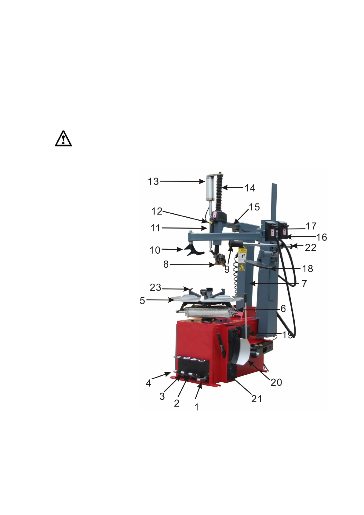
1.Rotation pedal
2.Bead breaker pedal
3.Rim clamp pedal
4.Tilt column pedal
5.trun table
6.Air Fiter
7.Tilt Column
8.Mount/ demount head
9.Bead press roller
10.Bead presser
11.Head lock handle
12.Head lock button
13.Mounting cylinder
14.Vertical bar
15.Horizontal bar
16.Mount/demount control
17.Assist arm control
18.Tire holder
19.Lubricant box
20.Bead breaker shovel
21.Bead breaker pad
22.Tire presser locker
23. Jaw
Fig.1
TECHNICAL DATA

3
External locking rim dimensions
10-20’’
Internal locking rim dimensions:
12- 24″
Max. tire diameter:
39’’(1000mm)
Max. tire width
410mm/16’’
Table top rotation speed
7/Min
Bead breaker Force (10bar)
2500kg/5500LBS
Working pressure
8-10 bar
Inflating pressure limiting device max.
3.5bar
Relief valve on inflating device
4 bar
Power supply voltage:
400v / 3phase
Motor power:
0.75 kW
Max rotation torque of turntable
1100 N.m
dimension
1370x1120x2020
Net weight:
280KG
Working noise:
<70 dB
TRANSPORTATION
The tire changer should be transported in its original packaging and kept
in the position shown on the package itself.
The packaged machine may be moved by means of a fork lift truck of
suitable capacity. Insert the forks at the points shown in figure 2
UNPACKING
Remove the protective cardboard and the plastic bag.
Check that the equipment is in perfect condition, making sure that no parts
damaged or missed. Use fig. 1 for reference.
If in doubt do not use the machine and contact your retailer.
Fig 2.
INSTALLATION
SPACE REQUIRED

4
•The tire changer must be connected to the mains electric power supply and the compressed air system.
It is therefore advisable to install the machine near these power sources.
•The place of installation must also provide at least the space shown in pictures 4 to ensure all parts of the
machine to operate correctly and without any restriction.
Fig 3.
POWER&AIR SOURCE CONNECTING
Even small jobs done on the electrical system must be carried out by professionally qualified personnel.
•Connect the machine to the compressed air system by means of the air connection that protrudes from the rear
section.
•Connect the machine to the electric network with the protection device of under-voltage, over-voltage, which must be
provided with line fuses, a good earth plate in compliance with regulations in force and it must be connected to an
automatic circuit breaker with RCD setting set at 30 mA.
Note: Should the tire-changer be lacking in electric plug, so the user must set one, which is at least 16 A
and which conforms to the voltage of the machine, in compliance with the regulations in force.
TRIAL OPERATION
The turntable should be turn clockwise when foot pedal K pressed down, while rotate anticlockwise when pulled

5
up.
Note: If the turntable turns in the opposite direction to that shown, reverse two of the wires in the
three-phase plug.
Make sure that you have known clearly the functions of every foot pedals and other important parts:
Pressing the pedal (4) to tilt the arm; when the pedal is pressed
again it returns to its normal position.
Pressing the pedal (3) to opens the four jaws, the jaw holders
will close again when pedal pressed again.
Pressing the bead breaker pedal (2) to operate bead breaker,
the breaker returns to its original position when pedal released.
Pressing foot pedal K to run the turntable clockwise, while pulling up to run anticlockwise. FIG 4
The mounting head positions itself automatically at the correct distance from the rim.
MOUNTING HELPER
Pneumatic mounting helper is used to mount/demont low profiled wheel.
conical tire demounting plate 18, tire pressing block 10,
Conical pressing roller 9, Tool cabin, and control valve 17
to control the whole helper go up and down
Fig 5.
INSTALLATION

6
Attention:1. The minimum space between the machine and the wall is 0.5 meter.
2. Always keep the machine indoor and dry place.
2.1. Position the machine over a solid concrete pedestal, and fix it with anchor bolt.
2.2 Connect compressed air with 8mm air hose to the Air Filter inlet, keep it tight and adjust the
air pressure to 0.6-1.0Mpa(6-10kg/cm), as shown in Fig. 2.
2.3 Electric power connection
● The job must be conducted by a trained person.
● Connect the proper power voltage in accordance with the rated voltage indicated on the plate.
● Make sure the machine is earthed properly.
● After the power connection, check the pedal 1, the rim clamp shall be rotating clockwise by pushing the pedal
and runs counterclockwise by lifting it. (for 3 phases model, rotation direction must be checked by swapping phase
line)
2.4 Trouble shooting during installation
Phenomenon
Causal reason
Solution
No rotation shows while pushing
the pedal
1.Power plug unconnected
2. Power plus cut off
3. Improper power source
Check the power input and rectify it
Rotating reversely by pushing the
pedal (for 3 phase model)
Phase sequence incorrect
Swap 2 of the phase lines.
Rotation speed too low
1. Power voltage is too low
2. Transmission belt wrong
1. Check power supply voltage
2. Fix the belt.
If the problem can not be solved, call your local distributor.
SYSTEM OVERVIEW
Fig.2

7
3.1 Mounting/demounting head and Assist Arm control system
3.1.1. Connect compressed air with 8mm air hose to the Air Filter inlet, keep it tight and adjust the air pressure to
0.6-1.0Mpa(6-10kg/cm).
3.1.2. Push the head lock button (12) to unlock the both vertical and horizontal bars for the mount head, and check
the movements on both axis, get ready for operation.
3.1.3. Push the assist arm control valve(17) to check the movement of the assist arm, pull out the bead roller (9)
to the wheel and keep 8mm space to the rim, lock the roller bar with the locker (22).
3.1.4.Lift the mounting control valve (16) and check the mounting hook move downward driving by the cylinder
(13) , push sown the control valve (16) to check the upward movement of the hook. This is the movement
the bead lifting.
3.1.5 The mounting head (8) mount the tire onto the rim or demount a tire from a rim , with the help of the assist
arm.
3.2 Rim center clamping system
The rim clamping table rotates through a gear box powered by the main motor, clockwise and
counterclockwise.
3.3 Pedal Control system
3.3.1 Push pedal 1 to rotate the clamping table clockwise, and lift the same pedal to rotate it counterclockwise.
3.3.2 Push pedal 2 to empower the bead breaker and release the pedal to reset it.
3.3.3 Push pedal 3 to lock and unlock rim clamp.
3.3.4 Push pedal 4 to control the tilt column in ether positions.
4. OPERATION
! IMPORTANT: Operators must be trained prior to operation.

8
4.1 Before demounting a tire
● Deflate the tire
● Undo the valve spindle
● Remove all balance weights applied on the rim, if any.
● Open the bead breaker shovel and position the tire into the space between the shovel
and the press pad, push the pedal 2 to break the bead, and repeat this step for other
positions of the bead, as shown in the Fig. 3.
4.1.1 Clamp the wheel
● Unlock the mounting tool bar before clamping the wheel onto the clamping table.
● Position the wheel on the clamping table, make sure the direction of tire mounting is
correct, center the rim into the clamp shaft, position one of the lug hole into the lock pin.
● Position the clamp shaft into the clamp centering hole, slide into the slot and hook up the
shaft by rotating 45 degrees.
● Push the pedal 3 to lock the rim , get ready for mount or demount a tire.
4.2 Positioning the mounting head
● Prior to mounting or demounting a tire, tilt back the tool column and keep the
mounting tool in the highest position.
● Keep the distance between the mounting/demounting head and rim to
ensure rim-tire from damaging during operation.
● Push the button to lock the tool bar vertically and horizontally, hold back the
button to unlock it, as shown in the Fig.5.
Attention! The plastic protection of the mounting head shall always keep away from the rim, to avoid
damaging.
4.3 Bead separation
4.3.1 Clamp the rim as per instruction described in section 4.1.1.
4.3.2 Move the tire pressing roller(9) towards the rim and keep a 1 cm distance , press the control valve 17 and
make the roller press the tire by 10-20mm, as shown in the Fig 6 and Fig.7.
Fig.4
Fig. 5
Fig. 3

9
4.3.3 Push the pedal 1 to rotate the tire by 1 to 2 circles until the upper bead separate from the rim, lift up the assist
arm control valve (17) to depress the press roller and release the locking nod and move the bar to the home
position
4.4 Demount a tire
4.4.1 Push the pedal 4 to reset the mounting tool in the position.
4.4.2 Rotate the tire and move the valve position away from the demounting head by
10 cm, put the mounting head in working condition.
4.4.3 Apply lubricant over the tire.
Note: proper lubricant must be applied, avoid using grease or oil to lubricate the tire. Fig. 8
4.4.4 Move the tire press roller (9) and press the tire by 2 cm, rotate until the bead is out of
the rim, push the hook control (16) and insert the hook into the gap between the bead and the
rim(Fig. 9). If the hook did not reach to the position of the tire, rotate the clamp table
counterclockwise to make the hook to the position.
4.4.5 Lift the press roller (9), unlock and move to home position.
4.4.6 Push the demounting head control valve(16) and lift
the demounting hook to lever up the bead over the demounting head(Fig.10). Press the pedal 1 to rotate the wheel
until the tire split from the rim.
Fig. 8
Fig. 6
Fig.7
Fig. 9
Fig.10

10
4.4.7 Demounting lower bead.
Move the tire holder 18 under the lower side of the tire, rotate the wheel and lift up the holder at the same time.
Stop rotation as soon as the lower bead lifted up to upper edge of the rim, control the hook to lift the lower bead
over the upper rim edge, rotate again the wheel until the complete tire is out of the rim(Fig. 11).
4.5 Mount a tire
ATTENTION!Make sure the tire size is matching with the rim
4.5.1 Clamp the rim and rotate the valve position across to the mounting
head by 180 degrees. Press the tire onto the rim, and apply lubricant on it.
4.5.2 Push pedal 4 to reset the mounting tool in position.
4.5.3 Set the mounting head in working position and put the tire bead over
the back side of the head. Push the pedal 1 to rotate the rim, until the lower
bead slide into the rim(Fig. 12).
4.5.4 For tire with tube, insert the tube before the upper bead is mounted.
To mount the upper bead, apply lubricant onto the tire and mounting head,
rotate the rim until the tire moved to the mounting head by 10 to 20 cm, put
the presser roller (9) and presser (10) on the tire , keep 1-2 cm space to the
edge of the rim, control the valve 17 to press the tire by 2-4 cm, rotate the
rim until the tire is completely mounted on to the rim(Fig. 13)
4.5.5 Release the assist arm by lift up the control valve 17, move the presser and roller to home position.
4.5.6 Unlock the mounting/demounting head and move it to home position , and lock it again. Push the pedal 4 to
tile the column.
4.5.7 Push pedal 3 to unclamp the rim, unlock the clamping shaft 5 and remove it from the center hole.
ATTENTION:
1. Incase the same sized tire and rim are applied, push the pedal 2 to keep same position
without repeating setting head position.
2. During clamping the rim on the table, DO NOT rotate the clamp table (DO NOT PUSH or LIFT
the Pedal 1)
Fig. 11
Fig.12
Fig 13

11
INFLATING
Pay utmost attention when inflating the tires. Keep strictly to the following instructions.
A burst tire can cause serious injury or even death of the operator.
• Check carefully that the wheel rim and the tire are of the same size.
• Check the state of wear of the tire and that it has no defects before beginning the inflation stage.
• Inflate the tire with brief jets of air, checking the pressure after every jet.
• All our tire changers are automatically limited to a maximum inflating pressure of 0.35 MPa (51 psi).
In any case NEVER EXCEED THE PRESSURE RECOMMENDED BY THE MANUFACTURER.
•Keep your hands and body as far away as possible from the tire.
INFLATION WITH AIRLINE GAUGE
In the standard version our tire changers are supplied with an airline
gauge. To inflate a tire proceed as follows: Fig 19
•Connect the airline gauge fitting to the tire valve.
• Make a last check to be certain that tire and rim diameter correspond.
•Check to be certain that rim and beads are sufficiently lubricated. If
necessary lubricate some more.
•Seat the beads with short jets of air. Between air jets, check the air pressure on the inflator gauge.
•Continue to inflate the tire with short jets of air and constantly checking
the pressure between air jets until the required pressure has been
reached.
INFLATION WITH AIR BOX
Take down the air inflator from the inflation box.
Press half down of the foot pedal G to inflate the tire, and constantly checking
pressure until the required pressure has been reached.
Fig 20
NOTE: the foot pedal of G has two functions: press half down to inflate tire and press completely down for
bead blasting.

12
MAINTENANCE
GENERAL WARNINGS:
Unauthorized personnel may not carry out maintenance work.
•Regular maintenance as described in the instructions is essential for correct operation and long lifetime of the tire
changer.
•If maintenance is not carried out regularly, the operation and reliability of the machine may be compromised, thus
placing the operator and anyone else in the vicinity at risk.
Before carrying out any maintenance work, disconnect the electric and pneumatic supplies.
Moreover, it is necessary to break the bead load less 3-4 times in order to let the air in pressure go out of
the circuit.
MAINTENANCE OPERATIONS
٠Make sure there is enough lubricate oil in the oil cup of Air Filter.
٠Usually Check the air filter, push the draining valve of water/oil separator to drain the water. and add lubricated oil
to protect cylinders on time.
٠Clean the mounting bar to ensure smooth operation.
٠Tighten the drive belt by means of the special adjusting screw X on the motor support .
Defective parts must be replaced exclusively by expert personnel using the manufacturer’s spare parts .

13
TROUBLE SHOOTING
Turntable rotates only in one direction
Reverse broken
Replace reverse
Turntable does not rotate
Belt broken
Replace belt
Reverse broken
Replace reverse
Check for loose wires in motor plug or
the socket replace motor
Turntable locks while removing /mounting tires
Belt loose
Adjust belt tension
Clamps slow to open/close
Silencer clogged
Clean or replace silencer
Turntable does not lock the wheel rim correctly
Clamps worn
Replace clamps
Turntable cylinder(s)defective
Replace cylinder gaskets
The tool touches the rim during the tire removing/mounting operations
Locking plate incorrectly adjusted or
defective
Adjust or replace locking plate
Turntable locking screw losses
Tighten screw
Bead breaker pedal and clamp opening/closing pedal lock out of position
Return spring broken
Replace spring
Bead breaking operation difficult
Silencer clogged
Clean or replace silencer
Bead breaker cylinder gaskets broaden
Replace gaskets

14
ELECTRICAL & PNEUM. DIAGRAMS
115/230V-1PH
230V/400V-3PH
Table of contents
Other GATmatic Automobile Accessories manuals
Popular Automobile Accessories manuals by other brands

Waeco
Waeco MagicComfort MSH100 Installation and operating instructions

Modifry Products
Modifry Products DCI-3 manual

Over Armour Offroad
Over Armour Offroad PO-10RANGER-DRW01 Instructions for Installation and Care

Paruzzi
Paruzzi VW 181 manual

PAC
PAC RP4.2-TY11 instructions

Axis
Axis TQC100 instruction manual

Thule
Thule 1768 instructions

Cycle Country
Cycle Country ATV PLOW MOUNT Assembly & owners manual

Kuda-Phonebase
Kuda-Phonebase 280130 Installation instruction

Kolpin Outdoors
Kolpin Outdoors FRONT-CONNECT PLOW MOUNT KIT Assembly & installation manual

Westfalia
Westfalia 305 221 Installation and operation instructions

bosal
bosal 043221 Fitting instructions