GATmatic TWC-562S Instruction manual

TWC562S TIRE CHANGER
INSTALLATION, OPERATION, MAINTENANCE MANUAL
TIRE CHANGER
ITEM NO:TWC-562S
FOLLOW THE INSTRUCTIONS CAREFULLY TO GRANT THE MACHINE A CORRECT FUNCTION AND
LONG SERVICE LIFE.
KEEP THE MANUAL NEAR THE MACHINE ALL TIME
AND MAKE SURE ALL USERS HAVE READ THIS

TWC562S TIRE CHANGER
1
TABLE OF CONTENT
INTRODUCTION ------------------------------------------------------------------------------2
TRANSPORTATION-------------------------------------------------------------------------------3
UNPACKING----------------------------------------------------------------------------------------3
INSTALLATION------------------------------------------------------------------------------------3
Space required-----------------------------------------------------------------------3
Parts assembling-------------------------------------------------------------------------------------4
Power& Air source connecting---------------------------------------------------------------------4
Technical data----------------------------------------------------------------------------------------5
OPRATION------------------------------------------------------------------------------------------6
Trial operation----------------------------------------------------------------------------------------6
Breaking the beads----------------------------------------------------------------------------------6
Tire Demounting-------------------------------------------------------------------------------------7
Tire mounting----------------------------------------------------------------------------------------8
INFLATING ------------------------------------------------------------------------------------------9
Inflating with airline gauge------------------------------------------------------------------------9
MAINTENANCE--------------------------------- -------------------------------------------------10
TROUBLE SHOOTING --------------------------------------------------------------------------11
ELECTRIC AND PNEUM. DIAGRAMS----------------------------------------------12
TWC562S TIRE CHANGER
2
INTRODUCTION
Thank you for your purchase of this full automatic tire changer.
This guide has been made in order to supply the owner as well the user with the basic instructions for a correct
use of the machine
Read this guide carefully before using the machine and follow the instructions given by this guide carefully to
grant the machine a correct function, efficiency and a long service life.
INTENDED USE: This automatic tire changer has been designed and manufactured specially for mounting and
demounting tires onto/from rims.
Any other use is to be considered incorrect and unreasonable. HUTNG will not hold responsibility for any
damage caused from using of this tire changer for purposes other than those specified in this manual and
therefore inappropriate, incorrect and unreasonable.
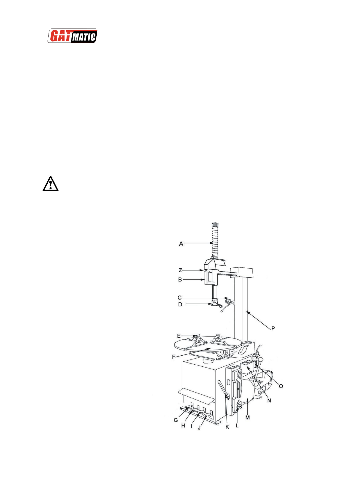
DESCRIPTION
A: Mounting bar
B: Locking handle
C: Air inflation
D: M/D head
E: Jaw
F: Turntable
G: Foot pedal, tilting arm
H: Foot pedal, jaw holder control
I: Foot pedal, bead breaker
J: Foot pedal, turntable control
K: Crowbar
L: Wheel support
M: Bead breaker
N: Soap reservoir
O: Water/oil separator
P: Tilting arm
Z:Locking push button
Fig.1
TWC562S TIRE CHANGER
3
TRANSPORTATION
The tire changer must be transported in its original packing and kept in the position shown on the package
itself.
The packaged machine may be moved by means of a forklift truck of suitable capacity.
UNPACKING
Remove the protective cardboard and the plastic bag.
Make sure that the equipment is in perfect condition, making sure that no parts damaged or missed.
Use fig. 1 for reference.
If in doubt, do not use the machine and contract your retailer,
INSTALLATION
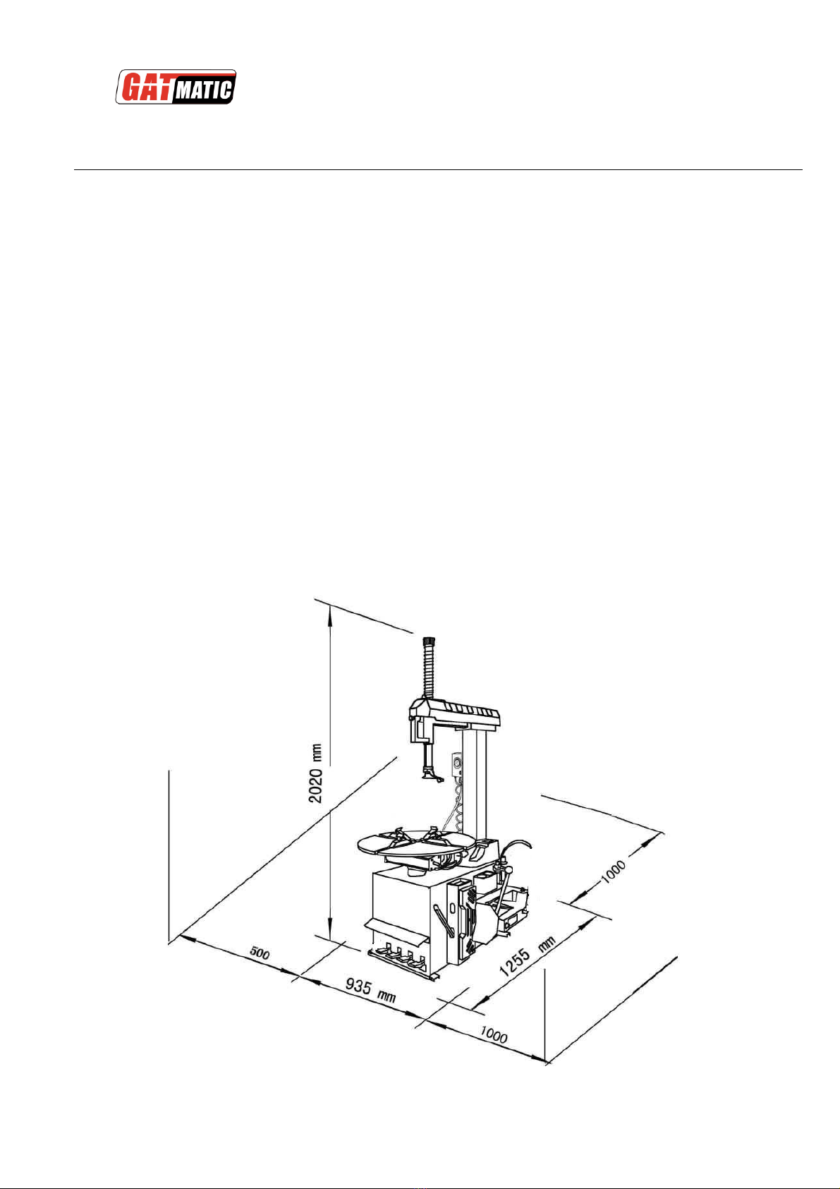
SPACE REQUIRED
When choosing the place of installation be sure that it complies with current safety at work regulations.
The tire changer must be connected to the electric power supply and the compressed air system.
The place of installation must also provide at least the space shown in figure 4 so as to allow all parts of the
machine to operate correctly and without any restriction.
Fig 2.

TWC562S TIRE CHANGER
4
PARTS ASSEMBLY
Unscrew the bolts on package and locate the tire changer in Suitable
place.
Assemble the changer as right pictures showing.
Fig 3.
POWER&AIR SOURCE CONNECTING
Before making the connections, check that the characteristics of
your systems correspond to those required by the machine
• Steady state voltage: 0,9-1,1 of nominal voltage.
Frequency: 0.99-1.01of nominal frequency continuously; 0.98-1.02 short time.
HVF:0.02.
Site Operating Conditions:
a. Altitude are not exceeding 1 000 m,
b. Maximum ambient air temperature is +40 C, minimum ambient air temperature is not less than 0 C,
c. Storage and transportation temperature range is -15C ~40C.
d. The relative humidity does not exceed 50% at a maximum temperature of +40 C, higher relative humidity may be permitted at
lower temperature (e.g. 90%@ 20C ).
e. The splitter can be stored or transported under ambient temperatures between –25C and +55C.
Even small jobs done on the electrical system must be carried out by professionally qualified personnel.
•Connect the machine to the electric network with the protection device of under-voltage, over-voltage, which must
be provided with line fuses, a good earth plate in compliance with regulations in force and it must be connected
to an automatic circuit breaker with RCD setting set at 30 mA.
•Connect the machine to the compressed air system by means of the air connection that protrudes from the
rear section as shown in the diagram 12.
Note: Should the tire-changer be lacking in electric plug, so the user must set one, which is at least 16 A and
conforms to the voltage of the machine, in compliance with the regulations in force.

TWC562S TIRE CHANGER
5
TECHNICAL DATA:
External locking rim dimensions
10-22’’
Internal locking rim dimensions:
12- 24″
Max. tire diameter:
1040mm/41’’
Max. tire width
410mm/16’’
Table top rotation speed
7r/Min
Bead breaker Force (10bar)
2500kg/5500LBS
Working pressure
0.8Mpa
Power supply voltage:
110V/60HZ, 220V/50HZ, 220V/60HZ
380V/50HZ
Motor power:
0.75 kW
Dimensions:
1150×1000×1170mm
Net weight:
220kg
Working noise:
<70 dB
Before connecting, make sure the power you will connect meets the machine requirement.
Check from the nameplate behind the machine.

TWC562S TIRE CHANGER
6
OPERATION
This part of the operating instructions shows basic operation and use of control. All operators should know clearly the
instruction before using the machine to prevent damaging machine and injured standby.
Before carrying out any operation, deflate the tire and take off all the wheel balancing weights.
The operation of the tire changer is divided into three parts:
a) BREAKING THE BEAD
b) TIRE DEMOUNTING
c) TIRE MOUNTING
The turntable should be turn clockwise when foot pedal J pressed down, while rotate anticlockwise when pulled up.
Note: If the turntable turns in the opposite direction to that shown, reverse two of the wires in the three-phase plug.
Make sure that you have known clearly the functions of every foot pedals and other important parts:
Pressing foot pedal J to run the turntable clockwise, while pulling up to run anticlockwise.
Pressing the pedal (G) to tilt the arm; when the pedal is pressed again it returns to its
normal position.
Pressing the pedal (H) to opens the four jaws, the jaw holders will close again when
pedal pressed again.
Pressing the bead breaker pedal (I) to operate bead breaker,
the breaker returns to its original position when pedal released. FIG 4
The mounting head positions itself automatically at the correct distance from the rim.
BREAKING THE BEAD
When the bead breaker pedal is operated, the bead breaker arm moves quickly and powerfully.
Anything within its range of action can be in danger of being crushed.
•Check that the tire is deflated. If not, deflate it.
•Close the turntable clamps completely
•Use the rubber bead breaker protection to protect the wheel rim.
Position the wheel against the rubber stops on the right side of the tire changer.
•Position the bead breaker blade against the tire bead at a distance of about
1 cm from the rim (fig.5). Pay attention to the blade, which must operate correctly
onto the tire and not onto the rim.
•Press down the pedal I to activate the bead breaker and release it when the blade
has reached the end of its travel or in any case when the bead is broken.
•Rotate the tire slightly and repeat the operation around the entire circumference of Fig 5
the rim and from both sides until the bead is completely detached from the rim
TWC562S TIRE CHANGER
7
TIRE DEMOUNTING
Before any operation remove the old wheel balancing weights and check that the tire is deflated.
Failure to use the grease supplied risks causing serious damage to the tire bead
•Press pedal H to tilt the arm thereby clearing the turntable
•Spread the supplied grease (or grease of a similar type) onto the tire bead.
During rim locking NEVER keep your hands under the tire. For a correct locking operation set the tire exactly in the
middle of turntable.
OUTER LOCKING
• Position the clamps according to the reference mark on the turntable by pressing pedal (I) down to its intermediate position.
• Place the tire on the clamps and, keeping the rim pressed down, press the pedal (I) as far as it will go.
INNER LOCKING
• Position the clamps so that they are completely closed.
• Place the tire on the clamps and press down the pedal(H)
•Return the arm by pressing the pedal (G).
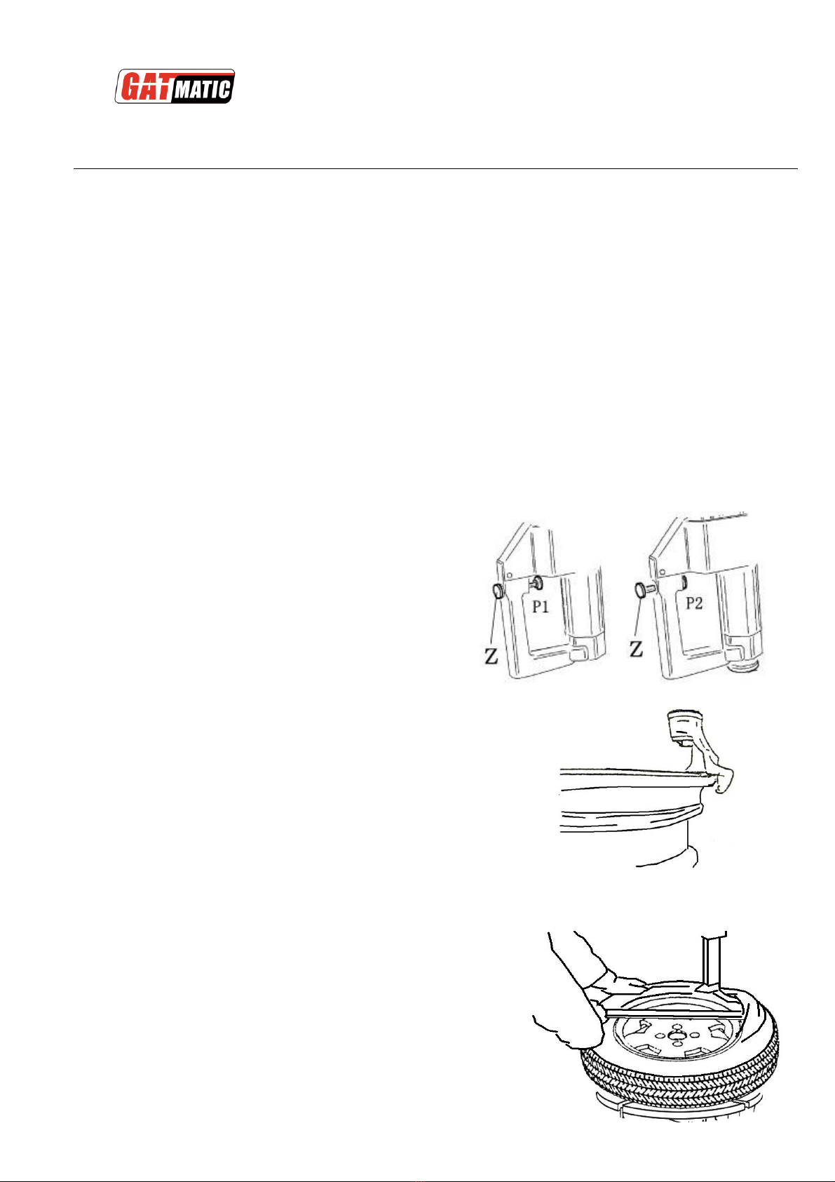
Position 1 of the locking button locks the mounting bar and arm.
Position 2 of the locking button unlocks the arms.
The mounting head positions itself automatically at the correct
distance from the rim.
Fig 6
-Lowering the mounting bar unit the mounting/demount head lean
against the rim edge.
-Lock the mounting arm with pushing locking button and now the
mounting/demounting head should be about 2 mm to rim edge.
Fig 7
NOTE: If it is tire with tube and in order to damage the tube, it is advisable to locate the tire valve about 10cm away with
the mounting/demounting head.
-Insert the crowbar into the tire as right picture showing. Fig 8
-Press foot pedal J to turn the turntable clockwise until the tire separated from the rim..
Withdraw the tube, if has, then repeat the operation with the other side.
-

TWC562S TIRE CHANGER
8
TIRE MOUNTING
This checking of tire and rim is of the utmost importance to prevent tire explosion during the inflating operations.
Before beginning mounting operation make sure that:
The tire and the cord fabric are not damaged.
The rim is without dents and is not warped.
Attention with alloy rims, dents cause internal micro-cracks not visible to naked eye.
This can compromise the rim and can also be a source of danger especially during inflation.
The diameter of the rim and tire are exactly the same. NEVER try to mount a tire on a rim if you cannot identify the
diameters of both.
Lubricate the tire beads with the special grease in order to avoid damaging them and to facilitate the mounting
operations.
-Press the foot pedal G to tilt back the arm about 300backward, operate it back after the rim locked on the turntable.
-Pushing the tire into the rim groove by hand, press the foot pedal J Fig 9
to turn the table clockwise, until the upper part of tire seated into the rim. (Fig9).
-Locate the M/D head at the rim edge.
-Place one end of tire over rear part of M/D head, while the other end on the M/D head.
-Press foot pedal J to make turntable run clockwise unit the lower part mounted onto the rim.
Repeat the above operation to mount the upper part of the tire. Fig 16
Mounting first the tube if has, then repeat the above operation if you are dealing with a tube tire.

TWC562S TIRE CHANGER
9
INFLATING
Pay utmost attention when inflating the tires. Keep strictly to the following instructions.
A burst tire can cause serious injury or even death of the operator.
• Check carefully that the wheel rim and the tire are of the same size.
• Check the state of wear of the tire and that it has no defects before beginning the inflation stage.
• Inflate the tire with brief jets of air, checking the pressure after every jet.
• All our tire changers are automatically limited to a maximum inflating pressure of 0.35 MPa (51 psi).
In any case NEVER EXCEED THE PRESSURE RECOMMENDED BY THE MANUFACTURER.
•Keep your hands and body as far away as possible from the tire.
INFLATION WITH AIRLINE GAUGE
In the standard version our tire changers are supplied with an airline
gauge. To inflate a tire proceed as follows: Fig 10
•Connect the airline gauge fitting to the tire valve.
• Make a last check to be certain that tire and rim diameter correspond.
•Check to be certain that rim and beads are sufficiently lubricated. If
necessary lubricate some more.
•Seat the beads with short jets of air. Between air jets, check the air pressure on the inflator gauge.
•Continue to inflate the tire with short jets of air and constantly checking
the pressure between air jets until the required pressure has been reached.
INFLATION WITH AIR BOX
Take down the air inflator from the arm.
Inflate the tire, and constantly checking pressure until the required pressure has been
reached.
Fig 11
TWC562S TIRE CHANGER
10
MAINTENANCE
GENERAL WARNINGS
Unauthorized personnel is not allowed to carry out maintenance work.
Before carrying out any maintenance work, disconnect the electric and pneumatic supplies. Moreover, it is necessary to break the
bead load less 3-4 times in order to let the air in pressure go out of the circuit.
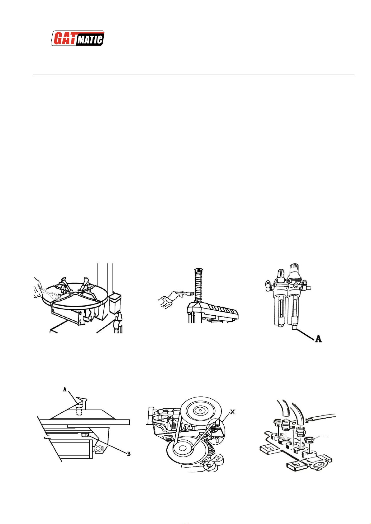
1.Clean the turntable every two weeks and lubricate the sliding groove of jaw holders. (Fig 12)
2.Clean the mounting bar to ensure smooth operation. (Fig 13)
3.Pull the draining valve of water/oil separator to drain the water. (Fig 14)
4.Replenish oil by checking the separator. Re-screw tightly the bolt A and B as Fig 15 instructing after the first 20 days using.
5.Check the tension of belt as following if the turntable is not powerful enough to run.
Unscrew the bolt from machine side, then dismount the board. Adjust the special bolt X to tight the belt. (Fig 16)
1. Clean or replace the foot pedal valve as Fig 17 showing.
.
Fig 12 Fig 13 Fig 14
Fig 15 Fig16 Fig 17

TWC562S TIRE CHANGER
11
TROUBLE SHOOTING
Turntable rotates only in one direction
Reverse broken
Replace reverse
Turntable does not rotate
Belt broken
Replace belt
Reverse broken
Replace reverse
Check for loose wires in motor plug or the socket
replace motor
Turntable locks while removing /mounting tires
Belt loose
Adjust belt tension
Clamps slow to open/close
Silencer clogged
Clean or replace silencer
Turntable does not lock the wheel rim correctly
Clamps worn
Replace clamps
Turntable cylinder(s)defective
Replace cylinder gaskets
The tool touches the rim during the tire removing/mounting operations
Locking plate incorrectly adjusted or
defective
Adjust or replace locking plate
Turntable locking screw losses
Tighten screw
Bead breaker pedal and clamp opening/closing pedal lock out of position
Return spring broken
Replace spring
Bead breaking operation difficult
Silencer clogged
Clean or replace silencer
Bead breaker cylinder gaskets
broaden
Replace gaskets
TWC562S TIRE CHANGER
12
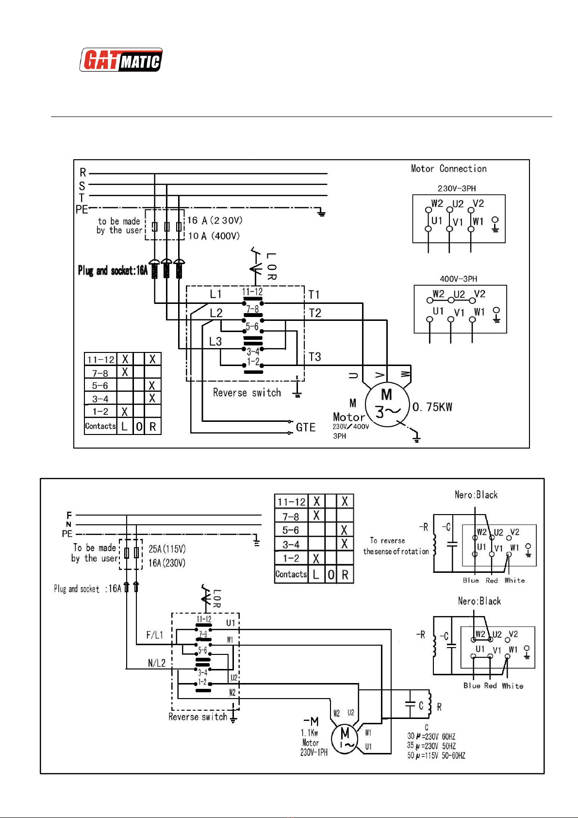
ELECTRICAL AND PNEUM. DIAGRAMS
115/230V-1PH
230V/400V-3PH
Table of contents
Other GATmatic Automobile Accessories manuals


