GAYLORD ClearAir RSPC-ESP SERIES User manual

TECHNICAL MANUAL
FOR
INSTALLATION, OPERATION
AND MAINTENANCE
OF
THE GAYLORD "ClearAirTM"
MODEL "RSPC-ESP" SERIES
POLLUTION CONTROL UNITS
WITH C-6000-ESP-S COMMAND CENTER
WARNING
Improper installation, adjustment, alteration service or
maintenance can cause property damage, injury or death.
Read the installation, operation and maintenance instruc-
tions thoroughly before installing or servicing this equipment.
Only trained and qualied service personnel should install
or service this equipment.
Effective Date: 12-12
10900 S.W. AVERY STREET • TUALATIN, OR 97062 USA
PHONE: 503-691-2010 • TOLL FREE: 800-547-9696 • FAX: 503-692-6048
email:[email protected] • www.gaylordusa.com
GAYLORD INDUSTRIES

2
GAYLORD INDUSTRIES
10900 SW Avery Street • Tualatin, OR 97062 U.S.A
www.gaylordusa.com • 800.547.9696
GAYLORD INDUSTRIES
GAYLORD INDUSTRIESGAYLORD INDUSTRIES
GAYLORD INDUSTRIES
Direct: 503.691.2010
Fax: 503.692.6048
Toll Free: 800.547.9696
Email: [email protected]
To Our Customers. . .
Congratulations on your recent purchase of a Gaylord ClearAirTM Pollution Control
Unit. We are proud to be able to provide you with a quality product that exemplifies
our long-standing dedication to quality engineering.
Your unit is assembled from some of the very finest components available and is
designed for years of efficient, effective, and trouble free operation. In addition, this
unit has undergone rigorous quality control inspections and was fully operationally
tested prior to shipment.
If you have further questions, please contact us toll free at 1-800-547-9696, or
Sincerely,
Gaylord Industries

TECHNICAL MANUAL
FOR
INSTALLATION, OPERATION
AND MAINTENANCE
OF
THE GAYLORD “ClearAirTM”
MODEL “RSPC-ESP” SERIES
POLLUTION CONTROL UNITS
WITH C-6000-ESP-S COMMAND CENTER
Published by:
GAYLORD INDUSTRIES
Tualatin, Oregon 97062
U.S.A.
First Printing: September, 2003
Second Printing: March, 2004
Third Printing: November 2012
The Gaylord ClearAirTM Unit is designed and engineered by
GAYLORD INDUSTRIES
10900 S.W. Avery Street
Tualatin, Oregon 97062
© Copyright 2003, Gaylord Industries
ALL RIGHTS RESERVED. NO PART OF THIS BOOK MAY BE REPRODUCED,
STORED IN A RETRIEVAL SYSTEM, OR TRANSMITTED IN ANY FORM BY
AN ELECTRONIC, MECHANICAL, PHOTOCOPYING, RECORDING MEANS
OR OTHERWISE WITHOUT THE WRITTEN PERMISSION OF GAYLORD
INDUSTRIES, INC. COPYRIGHT 2003.
The manufacturer reserves the right to modify the materials and specifications resulting from a continuing
program of product improvement or the availability of new materials.
Additional Copies $15.00

4
INTRODUCTION.....................................................................................................5
SPECIFICATIONS .............................................................................................. 6-7
MODEL NUMBER EXPLANATION .........................................................................8
TYPICAL INSTALLATION........................................................................................9
SAMPLE ClearAir TM CONFIGURATIONS ........................................................10-11
RECEIVING & INSTALLATION .............................................................................12
EQUIPMENT LIFTING PROCEDURE ..................................................................13
ASSEMBLING RSPC HOUSING ON UNITS SPLIT FOR SHIPMENT........... 14-15
SMOKE CONTROL...............................................................................................16
RSPC-ESP FIRE MODE ................................................................................. 17-18
DAILY OPERATION......................................................................................... 19-20
COMMAND CENTER INSTRUCTIONS.......................................................... 21-24
TIME CLOCK OPERATION...................................................................................25
DETERGENT PUMP OPERATION ................................................................. 26-27
PREVENTIVE MAINTENANCE....................................................................... 28-29
CELL CONFIGURATION.......................................................................................30
SPARE CELLS ......................................................................................................31
TROUBLE-SHOOTING – ESP SECTION....................................................... 32-33
ODOR CONTROL ........................................................................................... 34-37
EXHAUST FAN SECTION............................................................................... 38-39
RP DEVICE INITIAL START UP............................................................................40
TROUBLE-SHOOTING – GENERAL.............................................................. 41-44
DETERGENT PUMP PARTS ................................................................................45
CONTROL CABINET.............................................................................................46
SUB PANEL...........................................................................................................47
NAMEPLATE DATA ......................................................................................... 48-49
TERMINAL VOLTAGES................................................................................... 50-51
WIRING DIAGRAM ...............................................................................................52
OPTIONAL CONNECTION INSTRUCTIONS ........................................................ 53
PLC STATUS LIGHTS............................................................................................ 54
DRAIN .................................................................................................................... 55
SPRAY ODOR WIRING ......................................................................................... 56
SPRAY ODOR TERMINAL VOLTAGES ................................................................. 57
C-6000-ESP-S SERIES CONTROL.................................................................. 58,60
C-6000-ESP-S COMPONENT SCHEDULE...................................................... 59,61
POWER PACK PARTS........................................................................................... 62
CELL PARTS.......................................................................................................... 63
MISCELLANEOUS PARTS .................................................................................... 64
STARTUP INSTRUCTIONS ................................................................................... 65
INSPECTION REPORT.......................................................................................... 66
WARRANTY ..................................................................................Inside back cover
TABLE OF CONTENTS

5
Air quality is becoming a major concern in America’s large
cities and as a result, many commercial kitchens will
require pollution control equipment in their exhaust systems
to comply with the increasing demands of environmental con-
trol agencies. In addition, pollution control equipment is being
used for kitchens in high-rise buildings allowing the exhaust
to discharge out the side of the structure which saves the cost
of running the duct up many oors to the roof.
Pollution control in kitchen exhaust systems has typically been
accomplished by any one of the following methods - gas red
incinerators, scrubbers, ltration units or electrostatic precipita-
tors. Incinerators and afterburners literally burn the pollutants
and, while effective, can be very costly and hazardous to oper-
ate. Scrubbers consist of a water bath and extraction bafes
to remove the pollutants and though quite effective on grease
removal, they typically require the addition of high efciency
lters to abate smoke below control agencies’ standards. Fil-
tration units use a series of impingement lters to remove the
pollutants and if done properly can be quite effective on both
smoke and grease.
The Gaylord pollution control unit, trademarked “ClearAir”TM,
can be manufactured with either electrostatic precipitation
(ESP) or Filtration (TPF). Gaylord Industries has been manu-
facturing ESP’s specically designed for commercial kitchen
exhaust systems since the early 1970’s, longer than any
other manufacturer. However, when initial cost is a greater
concern the TPF unit is a sound alternative.
The ClearAirTM ESP unit is available in several congura-
tions, as illustrated on the following pages, ranging in ca-
pacity from 1000 to 32,000 CFM (472 to 15,102 L/s). Most
models can include an exhaust fan and odor abatement
equipment as an option.
Basic Facts About Smoke
Smoke particles are extremely small and not visible to the
human eye unless thousands of them are grouped together
to form what we see as smoke. Individual particles are
measured in units called microns and one micron equals
1/25,400 of an inch (1/64,516 of a cm).
Smoke generated by commercial cooking equipment has
a particulate size of 0.15 microns and it is these very small
particles that smoke abatement equipment must remove
from the airstream. The amount of smoke being discharged
from a kitchen exhaust duct is measured in terms of its den-
sity, referred to as opacity - the degree to which emissions
block light. A 100% opacity level would be solid black and
0% would be perfectly clear. Control agencies that have
adopted smoke pollution ordinances are requiring an opacity
level of no more than 20%, which is a very light blue smoke.
Typically, heavy smoke producing cooking such as charbroil-
ing, creates an opacity level of 60% to 70%. Opacity readings
are taken by the human eye by viewing the smoke being
discharged and then assigning a percentage of opacity to
what is seen. Though this method is quite subjective, it is
the method practiced by control agency inspectors who are
trained and certied in determining opacity percentages.
Other more technical methods of determining opacity or
particulate density are achieved through the use of opac-
ity meters and cascade impactors. This level of analysis
is usually referred to as source testing. Control agencies
occasionally require this type of analysis and if so, the test-
ing is conducted by state certied contractors which can
be quite costly and time-consuming. The efciency of an
TPF is based on how well it reduces the opacity level of a
given airstream.The Gaylord ClearAirTM unit will reduce the
opacity level below 20%, thereby meeting the requirements
of environmental control agencies.
Basic Facts About Odor
Cooking odors (molecules) generated by the combustion of
animal and vegetable matter result in an extremely complex
mixture of reactive organic gases (ROG’s). A small percentage
of these odors may be absorbed by the grease particles but
the vast majority exist separately in the airstream. The ROG
molecules are much too small to be removed by any type of
lter and therefore, other methods must be used. There are
several methods with which to manage the odor. One method
is to use a media bed. The three most popular types of media
bed are activated charcoal, which absorbs and retains the
odor molecules, the use of an odor-oxidant media (potassium
permanganate) which oxidizes the molecules to solids and
then retains them, and a blend of the two. Another method
involves the use of a liquid delivered with a nely atomized
spray. This spray performs a similar function to potassium
permanganate in that it adsorbs or chemically neutralizes
odors. This process has the benet of the end user being
able to adjust the amount of spray and thus the effective-
ness and cost of the odor control.
The life of the media bed type of odor control is dependent
upon several factors such as how much media is used, type
of odor, amount of odor molecules, grease loading and air
temperature. Typically, any of the above mentioned types of
media can remove 85% - 90% of the molecules. Determining
the efciency of odor control can be very subjective, as test-
ing is usually conducted by the human nose. More scientic
testing is available through ROG analysis, but this involves
considerable costs.
Grease Removal - The Important First Step
Grease particles are also measured in terms of microns and
grease generated by commercial cooking equipment has a
particulate size of 0.1 microns and up. Pollution control equip-
ment is not limited to removing smoke particles, but will also
remove a majority of the grease particles remaining in the
airstream. Therefore, the grease extraction efciency of the
exhaust hood plays an important role in the operation and
performance of pollution control equipment.
Removal of grease particles before they reach smoke
and odor control equipment will signicantly increase the
smoke abatement efciency and the life of the odor abate-
ment media.
INTRODUCTION

6
SPECIFICATIONS
General
Furnish one (1) Gaylord ClearAir Pollution Control Unit model
RSPC-ESP series as manufactured by Gaylord Industries
Inc. of Tualatin, Oregon in accordance with the following:
The pollution control unit shall consist of a smoke control sec-
tion, odor control section (optional) and an exhaust fan section
(optional) all built on a common base as an integral unit.
Smoke Control Section
The smoke control section shall contain one or more
electrostatic precipitator (ESP) cells to remove smoke
particles from the air stream to a level no higher than 20%
opacity when operated in accordance with the operation
and maintenance guidelines. The ESP cells shall be of a
oating plate design to eliminate plate warpage during high
heat operation. The cells shall be positioned on slide tracks
so that they may be easily removed through a hinged cell
access door(s). For ease of handling, individual cells shall
weigh less than 54 lbs. There shall be removable, cleanable
debris screens located immediately upstream of the ESP
cells and a moisture separator immediately downstream. An
electrical panel mounted on the unit shall contain the high
voltage power pack assembly, safety disconnect switch,
main disconnect switch, fuses and a magnetic starter for
the exhaust fan when fan is included. The safety discon-
nect switch shall interface with the electrical panel access
door such that when opened it will shut off service to the
power pack(s) and ground them to drain the residual elec-
trical charge from both the power pack(s) and ESP cells.
The ESP cell access door shall interface with the electrical
panel access door so that it cannot be opened without rst
opening the electrical panel access door. The high volt-
age power pack(s) shall be self-limiting type and shall be
self contained. The electrical panel shall include indicating
lights to monitor cell and transformer voltage. The main
disconnect switch for the exhaust fan and control circuits
shall lock the electrical panel access door closed when in
the “on” position. The unit shall contain one or more wash
manifold(s) with brass spray nozzles to wash the ESP cells
with hot detergent injected water each time the exhaust
fan is shut off.
Fire Detection
A thermostat, set at 250o F, shall also be located in the lter
section to shut down the exhaust fan in the event of a re.
Optional Fire Damper for use in Canada
The unit shall include a UL listed re damper, with a 280o
F fusible link, located downstream of the lters to prevent
passage of re to the duct downstream of the unit
Odor Control Options
Media bed of 50/50 Blend Potassium Permanganate and
Carbon Blend
The unit shall be provided with odor control utilizing a media
bed of 50% potassium permanganate 50% carbon blend.
There are two design methods of housing the media used
in the ClearAir unit. One is called the Loose Fill type and
the other is called the Media Panel type.
Loose Fill type – The odor control media shall be housed
in steel reusable Media Modules that can be replenished
with Loose Fill media. There shall be a 30% pleated media
After Filter located immediately downstream of the Media
Models. The Modules and After Filters shall be mounted
into slide tracks to prevent air bypass around the ends. The
Modules and After Filters shall be removable through side
access doors with lift and turn latches.
Media Panel type – The odor control media shall be com-
pressed into Media Panels that slide into Media Modules.
The Modules shall be mounted into slide tracks to prevent
air bypass around the ends. The Modules and shall be re-
movable through side access doors with lift and turn latches.
(optional) The unit shall be equipped with a 30% pleated
media After Filter located immediately downstream of the
Media Models.
The unit shall be equipped with a Single Pass Media Bed
The unit shall be equipped with a Double Pass Media Bed
The unit shall be equipped with a Triple Pass Media Bed
Spray Odor Control
The unit shall be provided with a spray odor control sys-
tem utilizing an odor neutralizer chemical. The odor spray
control cabinet shall be mounted on the side of the unit and
shall contain a liquid spray compressor piped to the spray
nozzle in the fan plenum, adjustable delay timers with fuse
protected circuitry factory wired to the unit electrical panel.
The cabinet shall include one 5 gallon container of Gaylord
Formula GS-710 Odor Neutralizer. The cabinet shall con-
tain a heater to prevent freezing of the odor neutralizer, if
mounted outdoors.
Exhaust Fan Options
Exhaust Fan (Standard Centrifugal Fan)
The unit shall include a centrifugal exhaust fan. The exhaust
fan shall be an SWSI upblast arrangement #9 or #10 with a
non-overloading BI or AF wheel. The motor, drives, bearings
and fan mounting base shall be located out of the exhaust
air stream as required by the IMC (International Mechanical
Code) and NFPA-96. The fan shall be AMCA certied and
bear the AMCA seal for performance. The fan housing shall
be constructed of heavy gauge steel. The fan bearings shall
be heavy duty self-aligning pillow block type rigidly mounted
on heavy structural steel supports. The motor shall be ODP
three phase mounted on a common base with the fan and
shall be pre-wired to the electrical cabinet located on the unit.
The electrical cabinet shall include a disconnect switch, motor
starter, overloads and fuses. The factory provided drive as-
sembly shall be adjustable pitch on 5 HP and smaller, xed
pitch on 7.5 HP and larger. It shall also be sized for a minimum
1.5 service factor. After nal system balancing, xed pitch
sheaves shall be provided and installed by the air balancing
contractor to provide proper ow at actual installed conditions.
Exhaust Fan (Optional Tubular Fan)
The unit shall include a tubular centrifugal exhaust fan. The ex-
haust fan shall be an arrangement #10 with a non-overloading
BI, AF wheel. The motor, drives, bearings and fan mounting
7
SPECIFICATIONS
base shall be located out of the exhaust air stream as required
by the IMC (International Mechanical Code) and NFPA-96.
The fan shall be AMCA certied and bear the AMCA seal for
performance. The fan housing shall be constructed of heavy
gauge steel. The fan bearings shall be heavy duty rigidly
mounted on heavy structural steel supports. The motor shall
be ODP three phase mounted on a common base with the fan
and shall be pre-wired to the electrical cabinet located on the
unit. The electrical cabinet shall include a disconnect switch,
motor starter, overloads and fuses. The factory provided drive
assembly shall be adjustable pitch on 5 HP and smaller and
xed pitch on 7.5 HP and larger. It shall also be sized for
a minimum 1.5 service factor. After nal system balancing,
xed pitch sheaves shall be provided and installed by the air
balancing contractor to provide proper ow at actual installed
conditions.
Exhaust Fan Housing
The exhaust fan section of the unit shall be enclosed with
the same material as the smoke control section. There shall
be a removable panel for access to the fan.
Unit Construction
The unit housing shall be constructed of a minimum of 16
gauge G90 bright galvanized steel. The perimeter base
shall be 12 gauge formed channel with lifting lugs at each
corner and along the length as required. The internal hous-
ing shall be externally welded liquid tight for compliance to
the International Mechanical Code and NFPA-96 grease
duct construction requirements.
Fire Extinguishing System Options
Specifier Note: NFPA-96 requires a fire extinguishing
system for protection of the smoke and odor control sec-
tions and protection of the duct down stream of any lters
or dampers. Not all authorities having jurisdiction require
protection. Check with your AHJ. If required, specify one
of the following systems.
Wet chemical system
Provide a complete factory mounted Ansul wet chemical
re extinguishing system, including nozzles piping and
detection runs. Pipe penetrating the unit cabinet shall use
a UL listed tting. System shall be installed in accordance
with the systems listing and NFPA-96. The Ansul Automan
cabinet shall be mounted on the side of the unit for easy
access, certication and service.
Water spray sprinkler re system
Specier Note: Units that are located indoors may be factory pre-
piped for a wet pipe building sprinkler system.
Provide a pre-piped water spray re system installed in ac-
cordance with NFPA-96. The unit shall be piped with one
pendent type sprinkler nozzle located in the smoke control
section, one in the odor control section, if equipped with 50/50
media bed, and one in the exhaust fan section for intercon-
nection to the building sprinkler system by the appropriate
trades. Pipe penetrating the unit cabinet shall use a UL listed
tting. Nozzles shall be the bulb type rated at 325o F.
ELECTROSTATIC CELL
ISOMETRIC VIEW SIDE VIEW
Check Out and Demonstration
Upon completion of installation, the entire pollution con-
trol system, including the kitchen exhaust hoods, shall
be commissioned by factory certied personnel. Start-up
shall include checking all lters, lter monitoring station,
odor control and exhaust fan. The appropriate mainte-
nance personnel shall be given a technical manual and a
complete demonstration of the system, including opera-
tion and maintenance procedures. Upon completion of the
commissioning, a detailed start-up report shall be made
available to the architect and owner certifying proper system
operation. Changes required in fan drive components shall
be performed by the air balancing contractor under the direc-
tion of the factory certied person(s) performing the start-up.
8
The assigned model number of a ClearAirTM RSPC-ESP unit will indicate the number of Cell Banks and if it has spray
odor control, single or double pass odor control, if it has an exhaust fan plus other data. The following example shows
the make-up of a model number.
The model number of your ClearAirTM unit along with other data can be found on the nameplate which is attached to the
electrical control panel on the ClearAirTM unit. Refer to page 49.
MODEL NUMBER EXPLANATION
RSPC - 1ESP - 3x2 - 500 - DW - DO - 9000 - EFN - C - 300 - 5 - R
Block 1 2 3 4 5 6 7 8 9 10 11
Standard Prex Series of ClearAir System (Remote Smoke Pollution Control)
1 ESP = Single Pass Electrostatic Cells
2 ESP = Double Pass Electrostatic Cells
ESP Cell Conguration (WxH) - 1x1, 2x1, 3x1, 2x2, 3x2, 4x2, 3x3, 4x3, 3x4, 4x4
Nominal FPM ESP Cell Velocity
250 FPM = Heavy and Extra Heavy Duty Cooking,
500 FPM = Light and Medium Duty Cooking
Number of Wash Banks
DW = Double Wash, Blank = Single Wash
Odor Control Option
SO = Single Pass Odor Control
DO = Double Pass Odor Control
SPO =Spray Odor
Total CFM
Exhaust Fan Option
EFS = Exhaust Fan, unhoused, spring isolated
EFN = Exhaust Fan, unhoused, not spring isolated
EFHS = Exhaust Fan, housed, spring isolated
EFHN = Exhaust Fan, housed, not spring isolated
(BLANK) = No Exhaust Fan
Fan Type - C = Centrifual, T = Tubular
Fan Size
Fan Motor H.P.
Hand - R = Right Hand
L = Left Hand
All Blank, if no exhaust fan
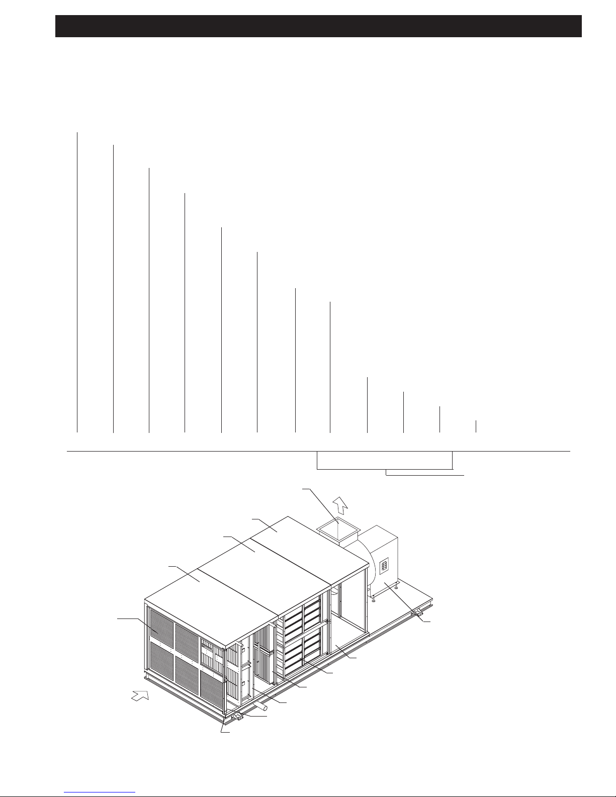
Exhaust Fan Section (EFN)
Plenum Section
Optional Spray Odor (SPO)
Odor Control (optional)
Section (SO, DO)
ESP section
ESP Cell
Conguration
(3 x 2)
Inlet Airow
Hand (Right Hand Access)
Access Side, R or L, Determined by Facing
Unit with Inlet Airow to back of head
Debris Screen
ESP Cells Single Pass (1ESP)
Moisture Separator
Odor Media (DO shown)
Plenum Access
Fan Type (Centrifual
or Tubular)
9
TYPICAL INSTALLATION
10
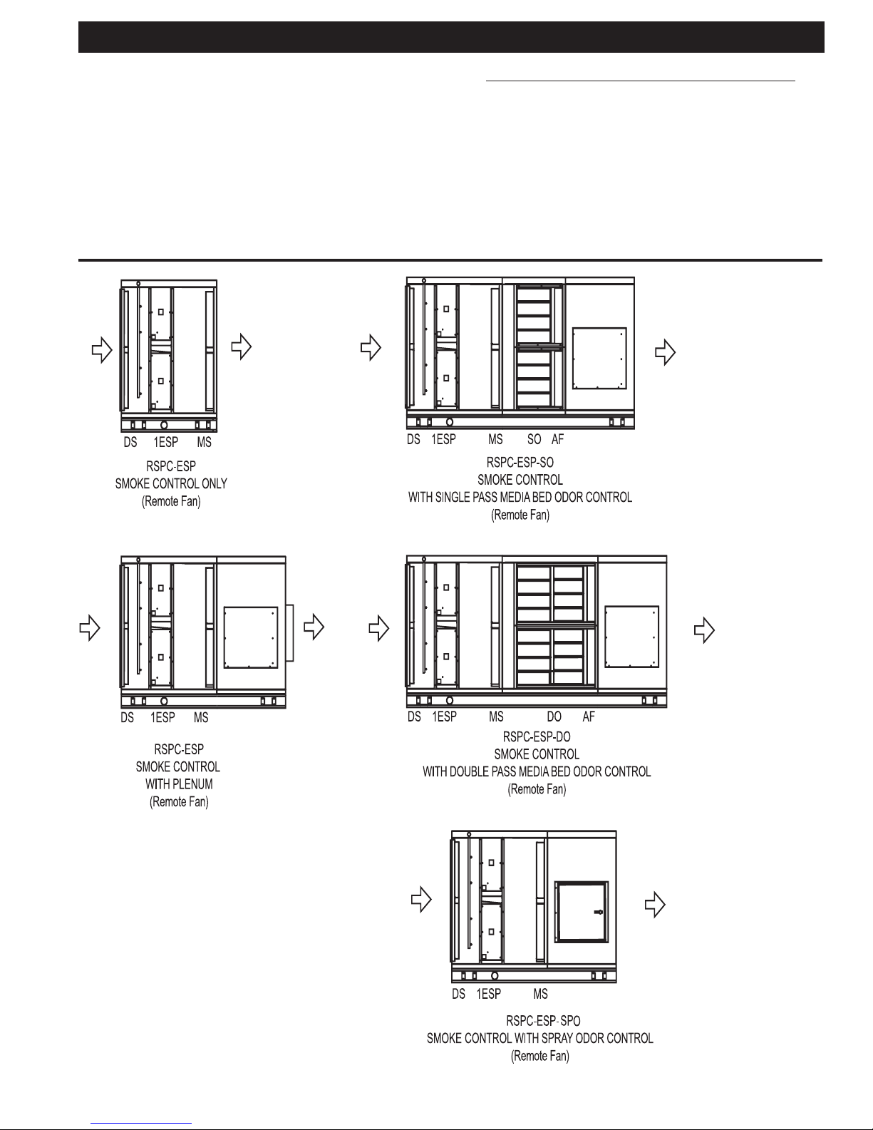
KEY
1ESP = Single Pass Electrostatic
Cells
2ESP = Double Pass Electrostatic
Cells
AF = 30% After Filter
DO = Double Pass Odor
Kor48/Carbon blend
DS = Debris Screen
EFS = Exhaust Fan, unhoused,
spring isolated
EFN = Exhaust Fan, unhoused,
not spring isolated
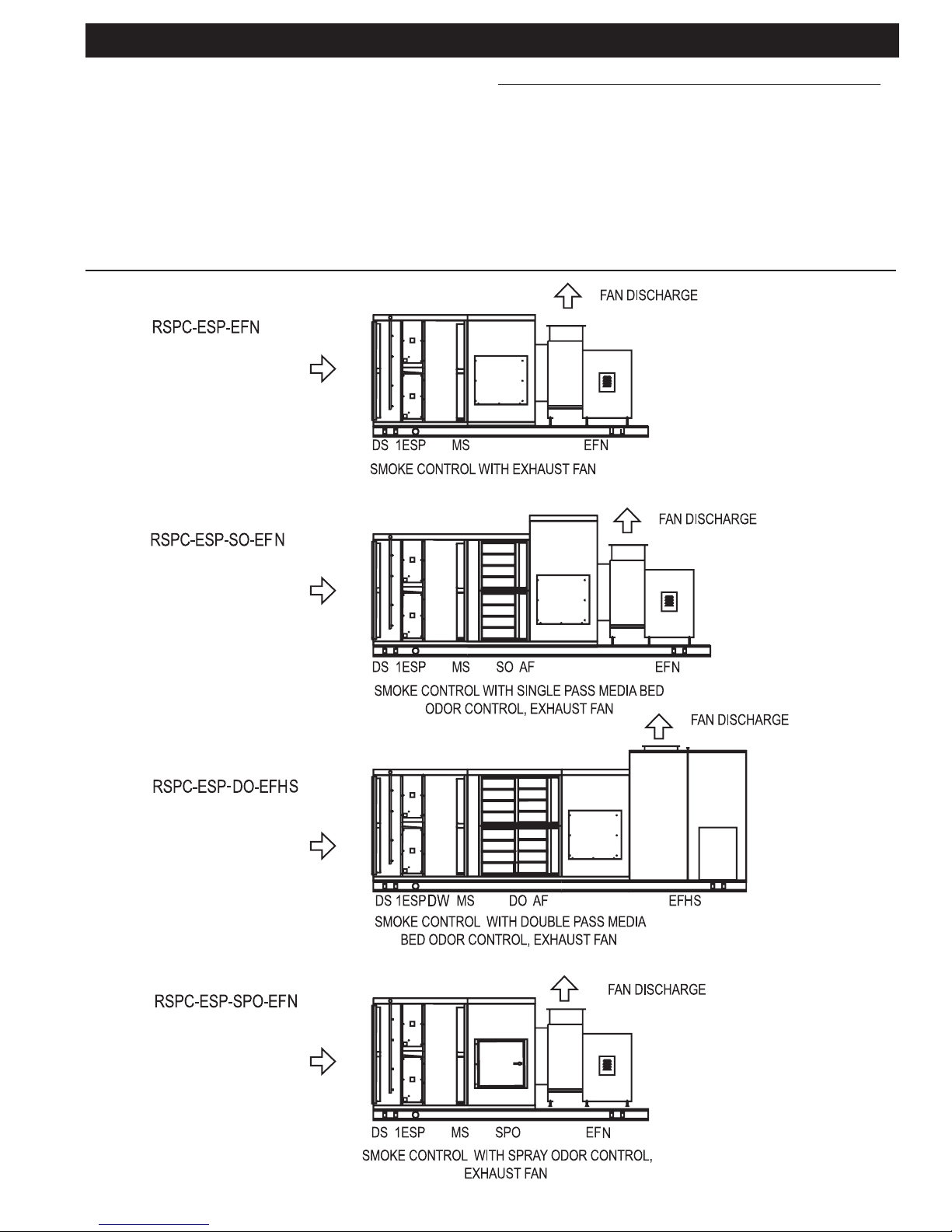
SAMPLE ClearAirTM RSPC-ESP CONFIGURATIONS
The ClearAirTM unit is available in sizes ranging in capacity
from 1000 to 32,000 CFM (472 to 15,102 L/s). Each unit is
equipped with Three Phase Filters for smoke control, and
may include an exhaust fan, odor abatement equipment
and Quencher System, or Ansul System as an option. The
following illustrations are examples of the most common
configurations.
EFHS = Exhaust Fan, housed,
spring isolated
EFHN = Exhaust Fan, housed, not
spring isolated
FD = Optional Curtain Fire
Damper
MS = Moisture Separator
SO = Single Pass Odor
Kor48/Carbon blend
SPO = Spray Odor Cabinet
11
SAMPLE ClearAirTM RSPC-ESP CONFIGURATIONS
KEY
1ESP = Single Pass Electrostatic Cells
2ESP = Double Pass Electrostatic Cells
DO = Double Pass Odor
Kor48/Carbon blend
DS = Debris Screen
DW = Dual Wash (2nd wash manifold)
EFS = Exhaust Fan, unhoused, spring
isolated
EFN = Exhaust Fan, unhoused, not
spring isolated
EFHS = Exhaust Fan, housed, spring
isolated
EFHN = Exhaust Fan, housed,
not spring isolated
FD = Optional Curtain Fire
Damper
MS = Moisture Separator
SO = Single Pass Odor
Kor48/Carbon blend
SPO = Spray Odor Cabinet

12
RECEIVING
Most ClearAirTM units are shipped in one piece. However,
some units, because of size or special jobsite conditions,
may be shipped in multiple sections. Follow the instruc-
tions provided with the unit to join sections back together.
If the unit includes media bed odor control, the KOR48/
carbon odor control media is packaged separately. Verify
against the shipping documents that you have received all
items and note any shipping damage, obvious or hidden, to
your carrier and on your Bill of Lading. If damage is found,
immediately le a claim with the transport company. All units
are thoroughly inspected and fully operation tested at the
factory prior to shipment.
Verify that the electrical and air ow ratings on the unit
nameplate agrees with jobsite requirements. If a contradiction
arises notify the factory prior to proceeding with installation.
SAFETY CONSIDERATIONS
Installing and servicing the ClearAirTM unit can be hazardous
due to the presence of electrical components. Only trained
and qualied service personnel should install or service
this equipment.
Untrained personnel can perform basic maintenance, such
as cleaning and replacing lters. All other operations should
be performed by trained service personnel. When installing
or servicing, observe precautions in literature and on tags
and labels attached to unit.
Follow all safety codes. Wear safety glasses and work
gloves. Use quenching cloth for brazing operations. Have
re extinguisher available. Read these instructions thor-
oughly.
WARNING
Before installing or servicing system, always turn off main
power to system. There may be more than one disconnect
switch. Electrical shock can cause personal injury or death.
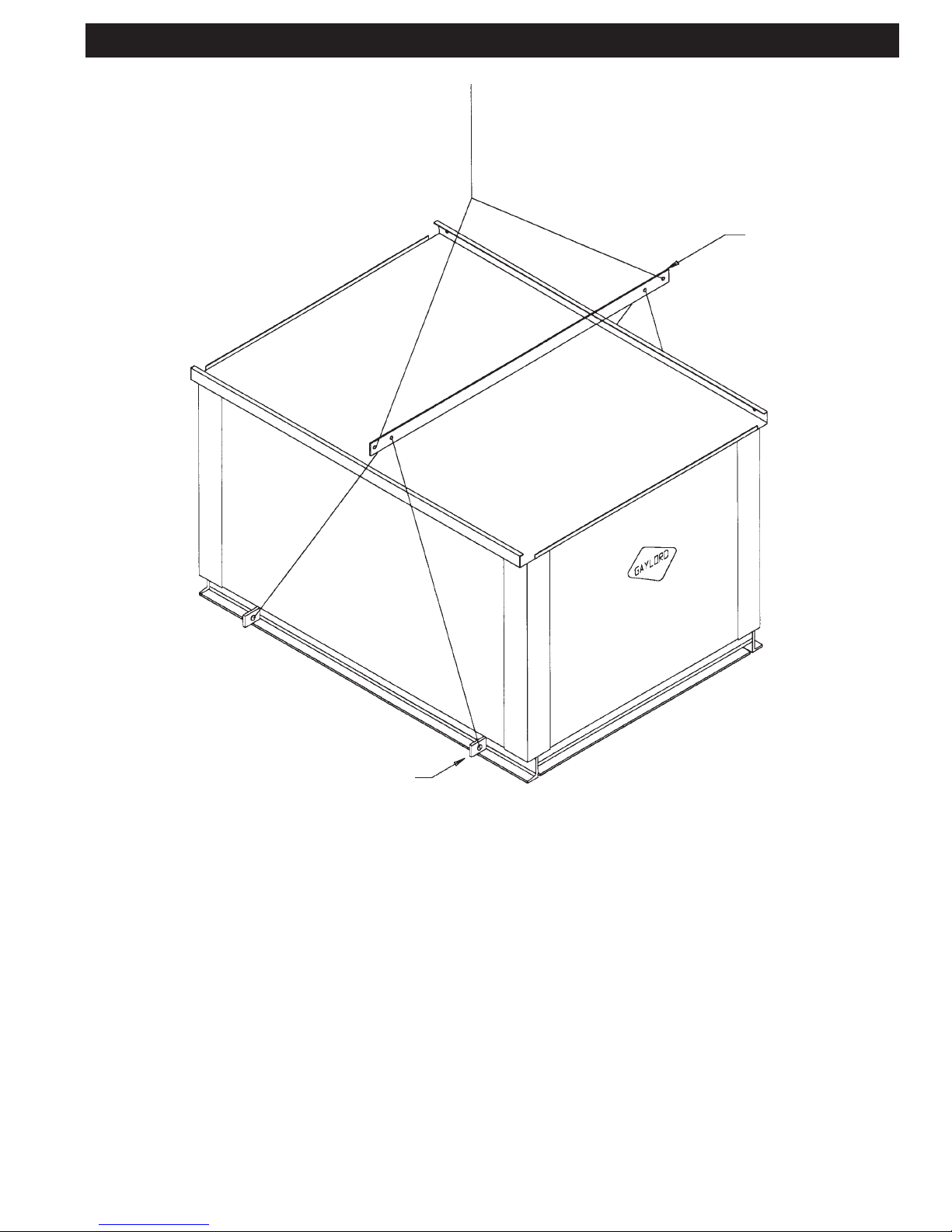
RIGGING
All units are provided with a minimum of four (4) lifting points
for rigging attachment. WARNING: Use all lifting points
provided. (Refer to Page 13) Spreader bars are mandatory
to prevent contact and damage to the unit by lifting hooks,
straps, cables, or chains. Consult the mechanical or struc-
tural engineer before moving the unit across the roof deck.
INSTALLATION CODES
This unit requires external plumbing and electrical connections
to be made in the eld. It is recommended that the Author-
ity Having Jurisdiction (AHJ) be consulted regarding local
codes and installation procedures. Gaylord Industries is not
responsible for obtaining necessary approvals and permits
which may be required for installation, nor is it responsible
for verifying that the unit has been installed in accordance
with national, state, and local codes. In the absence of locally
adopted codes use the current editions of the National Elec-
trical Code and the Uniform Mechanical Code. Connections
of the exhaust duct to the inlet and outlet of the ClearAirTM
unit must be fully welded to comply with NFPA-96.
INSTALLATION PRECAUTIONS
1. The services of qualied contractors are essential for
safe and proper installation of this equipment.
2. The air volumes and external static pressures that are
listed on the unit are for the middle of the operating range
of the lters. The initial air volume should be at least 10%
higher than the listed CFM. As the lters load up the air
volume will drop. This is inherent to this type of unit. If the
unit is set up at or below the design CFM, as the lters load
up, the kitchen hood may experience smoke loss problems.
Please consult the factory if you have questions.
3. The unit is designed for installation on a level surface.
4. When installed in an enclosed space a re rated enclo-
sure may be required for the unit and associated duct work.
Consult the Authority Having Jurisdiction.
5. Consult the Authority Having Jurisdiction regarding re-
quirements covering the point of termination of the exhaust
outlet of this unit. Minimum distances must usually be
maintained between the exhaust outlet and any outside air
intakes and/or adjacent structures or property lines.
6. Do not apply power to the unit until all electrical con-
nections have been made and a pre-start-up preliminary
inspection has been completed.
7. Allow a minimum of 36 inches clearance in front of the
lter access door and electrical compartment door for ser-
vice and routine maintenance per NEC.
SHORT TERM STORAGE
Units that include media bed odor control are provided with
KOR48/carbon media which is shipped separate from the
unit. KOR48/carbon media must be stored in a dry place
with less than 95% relative humidity.
EXHAUST FAN RECEIVING AND STORAGE
If the unit is equipped with an exhaust fan it must be re-
lubricated as soon as it arrives. To prevent corrosion all
bearings should receive grease and be rotated the rst of
every month. Rotate the wheel several revolutions every
three to ve days to keep a coating of grease on all internal
bearing parts. Turn the wheel by hand while greasing bear-
ings. A clean 1/16" bead of grease must appear on each
side of each bearing. Refer to specic bearing lubricating
instructions on the fan. Also, refer to bearing lubricating
instructions found in the exhaust fan section of this manual.
Bearings which are to be stored or idle for an extended
period of time should be wrapped in a neutral grease-proof
paper, foil, or plastic lm. Compounds can be recommended
by the bearing manufacturer to provide protection for sev-
eral months to several years.
After long-term storage, grease should be purged from the
bearings and fresh grease injected prior to start-up.
RECEIVING & INSTALLATION
13
EQUIPMENT LIFTING PROCEDURE
SPREADER
BAR
LIFTING
LUGS
1. All units are provided with a minimum of four lifting points for rigging attachment. All
lifting points must be used.
2. Spreader bars are mandatory to prevent contact and damage to the unit by lifting
hooks, straps, cables or chains.

14
1. Attach "ESP Section" to "Media Bed Odor Control
Section":
Bolt "Media Bed Odor Control Section" and "ESP Section"
bases together on outside of unit, using 3/4" holes. Tek
screw walls and roofs together, using 3/16" holes. Continu-
ously weld: oor, wall, and roof seams from inside of unit.
2. Attach "Media Bed Odor Control Section" to "Plenum
Section":
Bolt "Media Bed Odor Control Section" and "Plenum
Section" bases together on outside, using 3/4" holes.
From inside plenum, tek screw walls and roofs together,
using 3/16" holes. Continuously weld: oor, wall, and roof
seams from inside of unit.
3. Attach Fan Inlet to "Plenum Section" outlet:
Push "Exhaust Fan Section" about 7 inches from "Plenum
Section". Tek screw & caulk fan duradyne to plenum in-
terconnect ring, at 5 inch intervals (minimum). Duradyne
is pre-attached to fan inlet side.
4. Attach "Plenum Section" to "Exhaust Fan Section":
Bolt "Plenum Section" and "Exhaust Fan Section" bases
together on outside, using 3/4" holes. From inside of
plenum, tek screw walls and roofs together, using 3/16"
holes. Continuously weld oor seam from inside plenum.
"Exhaust Fan Section" walls and roof to remain removable
for exhaust fan replacement, tek screw and bolt only.
5. Assemble "Media Bed Odor Control Section":
Refer to "Media Bed Odor Control Section Assembly
Instructions" drawing.
6. Reconnect Electrical to Exhaust Fan
HOUSING ASSEMBLY INSTRUCTIONS
Typically, RSPC units are shipped as one piece. Sometimes for building accessibilty reasons a RSPC unit may be shipped
in multiple pieces. If this is the case, refer to the instruction below and on page 15.
15
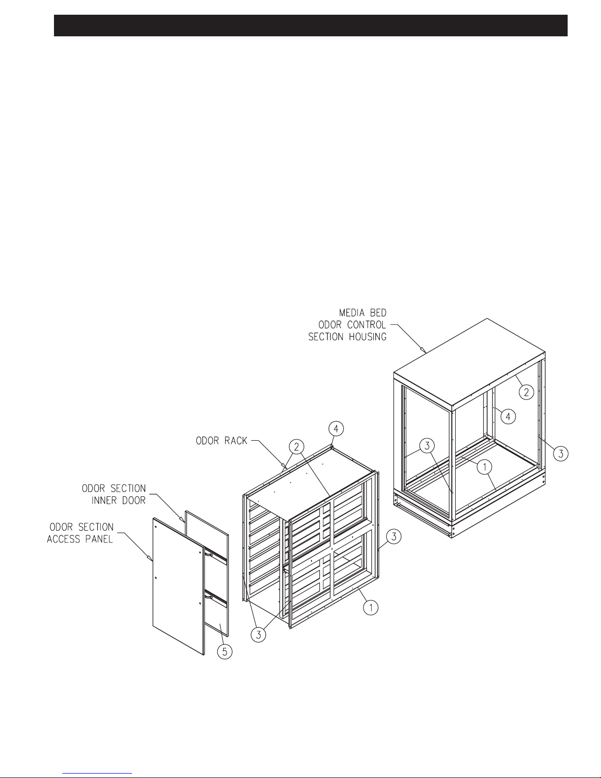
MEDIA BED ODOR CONTROL SECTION ASSEMBLY INSTRUCTIONS
NOTE: Assemble this section, only after the rest of
the unit has been assembled.
1.Slide odor rack into unit through door opening. Tek screw
rack to oor rails, using 3/16" holes.
2.Tek screw upper rack to both sides of roof rails.
3.Tek screw rst 3 sides to mouning rails from outside
of the unit.
4.Attach fourth side by entering odor rack to reach screw
holes.
5.Attach odor section inner door, ip latches to secure.
16
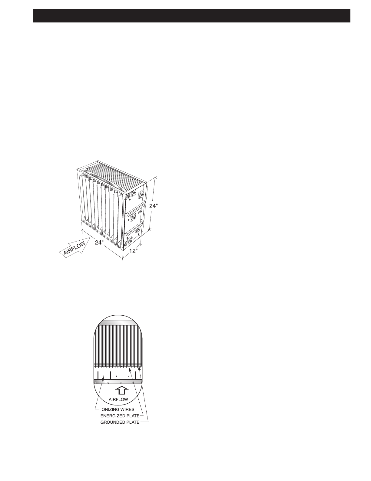
SMOKE CONTROL
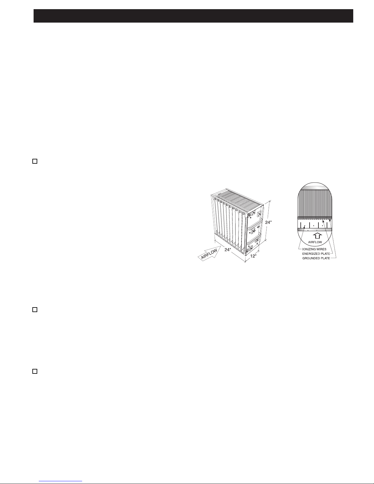
Principle of Operation
The ClearAirTM TM Pollution Control Unit removes smoke particles by
electrostatic precipitation. The principle of operation of electrostatic
precipitation is actually quite basic. The electrostatic cell is made up
of a series of aluminum plates spaced approximately 1/4” (6.35mm)
apart and the number of cells used is determined by the air volume
and the type of cooking equipment involved. Every other plate is
energized with 5000 volts of D.C. power and the alternating plates
are grounded. At the entry point of the cell is a series of thin wires
spaced approximately 4” (101.60mm) apart. These wires, referred
to as ionizing wires, are energized with 10,000 volts D.C. and as
the smoke particles enter the cell and pass over the wires they
receive a positive charge. As the charged particles continue through
the cell, the positive plate repels them and the negative or grounded
plate attracts them. Thus, the smoke particles are collected on the
negative plates. The action is efcient, safe and simple.
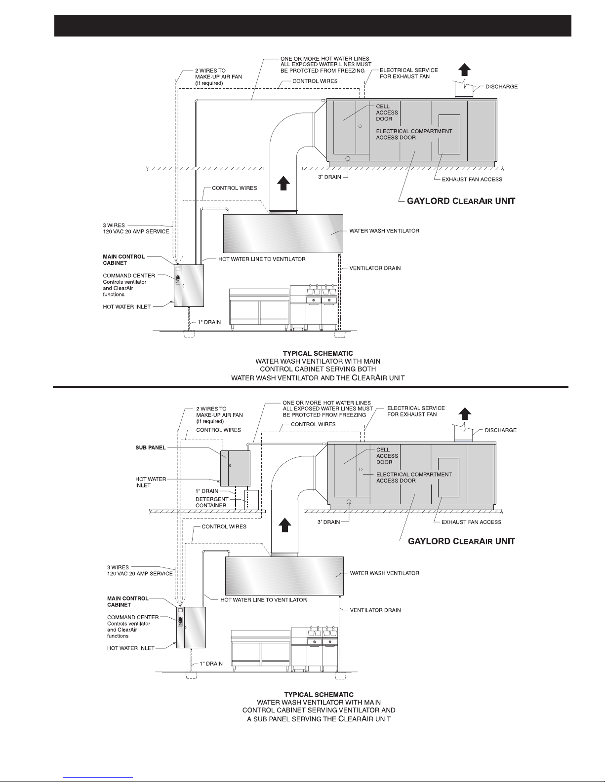
Wash Cycle
All Gaylord ClearAirTM units include, as standard equipment,
an internal washdown system and control cabinet which
when activated washes the unit with hot detergent injected
water to remove the daily accumulation of smoke and
grease particles. The washdown system and contols are
interfaced with the Gaylord Water Wash Ventilator. There
are two possible arrangements of controls for the opera-
tion of the Ventilator and the ClearAirTM Unit as illustrated
on page 9. In the rst arrangement the Control Cabinet in
the kitchen serves both the Ventilator and the ClearAirTM
Unit. The hot water solenoid valves and detergent pump
and container for both the Ventilator and ClearAirTM Unit are
located in this cabinet.In the second arrangement there is a
Control Cabinet for the ventilator electrically interfaced with
a Sub Panel that serves the ClearAirTM Unit. The hot water
solenoid valves and detergent pump for the ClearAirTM Unit
are housed in the Sub Panel and the detergent container
is located below or next to the panel. The detergent pump
and container for the Ventilator are both housed in the
main Control Cabinet located in the kitchen. In both ar-
rangements the Exhaust Fan, ESP, Wash Cycles and Fire
Cycle Functions are controlled by the Ventilator Control
Cabinet. The difference between the two is the location of
the plumbing components.
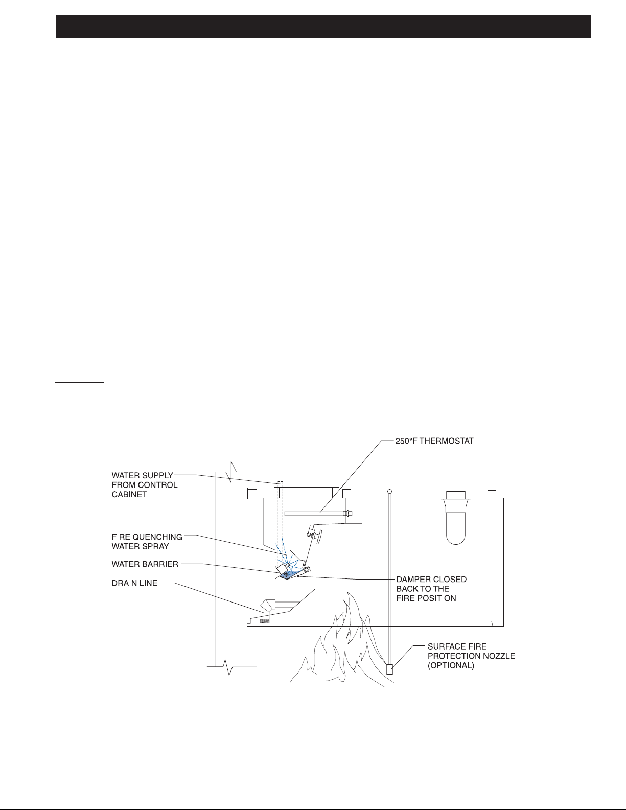
Fire Cycle
In the event of a re, a 250o F. thermostat, mounted in the
airstream, will activate shutting off the exhaust fan and ESP
cells, and turning on the water sprays within the ClearAirTM
Unit. The re cycle of the water wash ventilator will also
activate at this time. The water will run continually until the
thermostat cools below 250o F, and then run for another
2 minutes. At the conclusion of this cool down cycle the
exhaust fan may be started by pushing "Start Fan".
ISOMETRIC VIEW
SIDE VIEW
ELECTROSTATIC CELL
17
INTERNAL FIRE MODE
Automatic internal re protection is accomplished by the ac-
tion of the thermostat(s), which is located in the lter section
of the RSPC-ESP. When the temperature of the conveying
airstream, which must pass over the thermostats, reaches
250°F, the system is activated, and the following occurs:
1. The damper begins closing back to the re position, on
a Gaylord CG3 ventilator, if so equipped, position 3 as
shown in Fig.4—stopping the combustion-supporting,
natural draft through the ventilator and creating a re
barrier to contain the re in the kitchen.
2. The exhaust fan is shut off. The supply fan is also shut
off.
3. Fire-smothering water spray is released into the interior
of the RSPC-ESP through the spray nozzles.
4. The digital display reads "Fire In Hood, Fan Off, Wash
On" for approximately 5 seconds.
5. Then the digital display reads "Fire In Hood, Damper
Closing" for approximately 5 seconds.
6. Then the digital display reads "Fire In Hood, Notify Fire
Department". This display stays on until the thermostat
cools down below 250°F.
RSPC-ESP FIRE MODE
CAUTION:
In case of severe re the thermostats located in the lter
section will activate. As a precautionary measure, it is rec-
ommended that the thermostats be replaced.
FIRE CYCLE
7. A red light on the Command Center illuminates.
8. If the Command Center is intertied with a building alarm
or monitoring system, a re signal would be sent to that
system.
9. Upon cooling of the thermostat below 250oF, the Cool
Down Cycle starts. The water continues to spray during
the Cool Down Cycle (2 minutes). The damper moves
to the exhaust position, on a Gaylord CG3 Ventilator,
if so equipped.
10. While in the cool down cycle the digital display reads
"Cool Down Cycle, xxx sec. to end". xxx is the count-
down in seconds until the wash turns off.
11. At the end of the cool down cycle the water turns off and
the digital display reads "Fan Off 12:00 (actual time),
Start Fan>F1". The damper closes to the wash position
in a Gaylord CG3 Ventilator, if so equipped.
NOTE: The water may be shut off prior to the end of the 2
minute cool down cycle by pushing the “Exit” button on
the C-6000 Command Center. After the water has shut
off, the damper remains in the wash position on a Gaylord
CG3 Ventilator, if so equipped, until the “Start Fan” button
is pushed.
GAYLORD CG3 Ventilator
18
RSPC-ESP FIRE MODE
TESTING INTERNAL FIRE MODE
The internal re protection system may be tested periodi-
cally by pushing and holding for 20 seconds, the “Fire Test
Switch” located inside the electrical compartment of the
control cabinet. Pushing this switch duplicates thermostatic
action. CAUTION: Before pushing the “Fire Test Switch”,
check to see if the internal re protection system is tied to
the building alarm system.
TO RESUME NORMAL OPERATION
1. To discontinue the 2 minute cool down cycle at any
point during the cycle, push the “Exit” F5 button on
the C-6000 Command Center.
2. Push the “Start Fan” F1 button on the Command
Center.
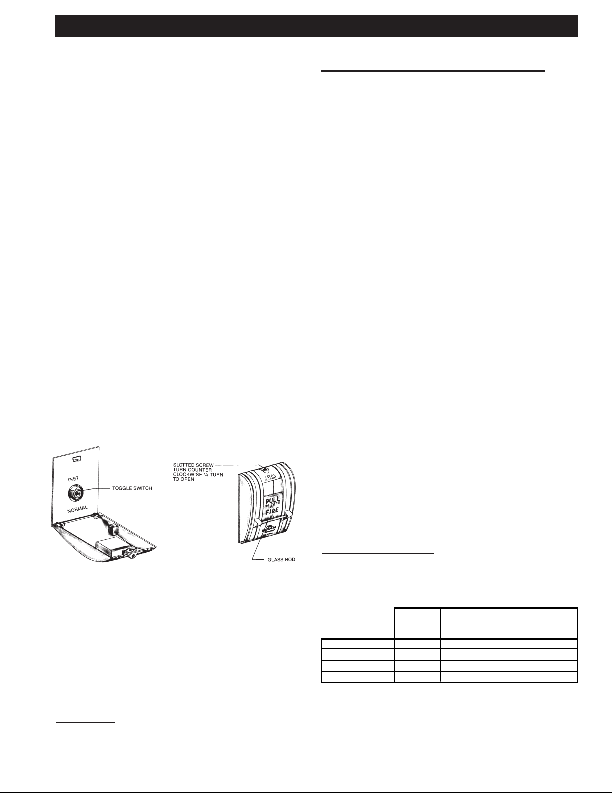
SURFACE FIRE PROTECTION
The National Fire Protection Association, NFPA-96 docu-
ment requires re extinguishing equipment over all grease
producing cooking equipment such as griddles, ranges,
fryers, broilers, and woks. In addition, the system must
protect the interior of the ventilator and the exhaust duct.
The most common re system is a wet chemical type. In the
event of a re this system would normally be activated and
discharged prior to the ventilator’s internal re protection.
If the re is unusually severe or the surface re protection
system malfunctions, the ventilator’s internal re protection
system would activate, thus providing a second level of
defense. These systems may be intertied with the ventilator
control cabinet to activate the External Fire Mode.
FIG. 5
BREAK GLASS FIRE SWITCH
C-1357A SERIES
EXTERNAL FIRE MODE
An External Fire Mode is activated by the Pollution Control
Units or Ventilator’s Fire Suppression (Duct, Plenum, Sur-
face/Appliance) system’s microswitch or contacts and/or an
optional break glass re switch (see Figure 5). Terminals
4 & FS are used for the External Fire Mode, refer to wiring
diagram for details. The break glass re switch, if used,
would normally be located at the exit of the kitchen. When
the External Fire Mode is activated, the following occurs:
1. The Exhaust Fan comes on immediately if it was off to
help remove smoke, heat, etc.
2. The Supply Fan shuts off immediately.
3. The digital display reads “Ext.FireActive” and alternates
between “Reset FireSwitch” and “Fan On, Wash On”.
4. A red light on the Command Center ashes.
5. After a 60-second delay, a re smothering water spray
is released into the interior of the RSPC-ESP and the
Gaylord CG3 ventilators, if so equipped, through the
spray nozzles.The 60-second delay allows the RSPC-
ESP's and ventilator’s re suppression system time to
put out the re, before starting the water spray.
If the re intensies and the thermostat reaches 250°F, the
re damper would then close on a Gaylord CG3 Ventilator,
if so equipped, and the exhaust fan would shut off. See
Internal Fire Mode.
To resume normal operations, open the re switch and ip
the toggle switch to the position marked “normal”. Replace
the glass rod and close the cover. Push either the “Start
Fan” or “Start Wash” button.
INTERNAL & EXTERNAL FIRE MODES AT THE SAME
TIME
It is possible that both the Internal and External Fire modes
can be activated at the same time. If this occurs, the Inter-
nal Fire Mode will override the External Fire mode until the
thermostat(s) cool below 250°F. At this point the Cool Down
Cycle will start counting down for 2 minutes. After the Cool
Down Cycle, the External Fire mode will start.
Special Note: If the control is in the Cool Down Cycle when
the External Fire mode is activated, the Cool Down Cycle
will nish counting down for 2 minutes, before switching to
the External Fire Mode.
FIRE MODE SUMMARY:
Note: The Damper Position applies to a Gaylord CG3 Ventilator,
if so equipped.
Summary of Both Fire Modes at the Same Time
1. Internal Fire Mode (until thermostat temperature
drops below 250°F)
2. Cool Down Cycle (for 2 minutes)
3. External Fire Mode (until the External Fire Switch
is reset)
18
RSPC-ESP FIRE MODE
TESTINGINTERNAL FIREMODE
The internal fire protection system may be tested periodi-
cally by pushing and holding for 20 seconds, the “Fire Test
Switch” located inside the electrical compartment of the
control cabinet. Pushing this switch duplicates thermostatic
action.
CAUTION: Before pushing the “Fire Test Switch”,
check to see if the internal fire protection system is tied to
the building alarm system.
TO RESUME NORMAL OPERATION
1. To discontinue the 2 minute cool down cycle at any point
during the cycle, push the “Exit” F5 button on the C-
6000 Command Center.
2. Push the “Start Fan” F1 button on the Command Center.
SURFACEFIREPROTECTION
The National Fire Protection Association, NFPA-96 docu-
ment requires fire extinguishing equipment over all grease
producing cooking equipment such as griddles, ranges, fry-
ers, broilers, and woks. In addition, the system must protect
the interior of the ventilator and the exhaust duct.
The most common fire system is a wet chemical type. In the
event of a fire this system would normally be activated and
discharged prior to the ventilator’s internal fire protection. If
the fire is unusually severe or the surface fire protection sys-
tem malfunctions, the ventilator’s internal fire protection sys-
tem would activate, thus providing a second level of defense.
These systems may be intertied with the ventilator control
cabinet to activate the External Fire Mode.
FIG. 5
BREAK GLASS FIRE SWITCH
C-1357A SERIES
EXTERNALFIREMODE
An External Fire Mode is activated by the Pollution Control
Units or Ventilator’s Fire Suppression (Duct, Plenum, Sur-
face/Appliance) system’s microswitch or contacts and/or an
optional break glass fire switch (see Figure 5). Terminals 4
& FS are used for the External Fire Mode, refer to wiring
diagram for details. The break glass fire switch, if used,
would normally be located at the exit of the kitchen. When
the External Fire Mode is activated, the following occurs:
1. The Exhaust Fan comes on immediately if it was off to
help remove smoke, heat, etc.
2. The Supply Fan shuts off immediately.
3. The digital display reads “Ext.FireActive” and alternates
between “Reset FireSwitch” and “Fan On, Wash On”.
4. A red light on the Command Center flashes.
5. After a 60-second delay, a fire smothering water spray
is released into the interior of the RSPC-ESP and the
Gaylord CG3 ventilators, if so equipped, through the spray
nozzles.The 60-second delay allows the RSPC-ESP's
and ventilator’s fire suppression system time to put out
the fire, before starting the water spray.
If the fire intensifies and the thermostat reaches 250°F, the
fire damper would then close on a Gaylord CG3 Ventilator, if
so equipped, and the exhaust fan would shut off. See Inter-
nal Fire Mode.
To resume normal operations, open the fire switch and flip the
toggle switch to the position marked “normal”. Replace the
glass rod and close the cover. Push either the “Start Fan”
or “Start Wash” button.
INTERNAL&EXTERNALFIREMODESAT THE SAMETIME
It is possible that both the Internal and External Fire modes
can be activated at the same time. If this occurs, the Internal
Fire Mode will override the External Fire mode until the
thermostat(s) cool below 250°F. At this point the Cool Down
Cycle will start counting down for 2 minutes. After the Cool
Down Cycle, the External Fire mode will start.
Special Note: If the control is in the Cool Down Cycle when
the External Fire mode is activated, the Cool Down Cycle
will finish counting down for 2 minutes, before switching to
the External Fire Mode.
FIREMODE SUMMARY:
Note: The Damper Position applies to a Gaylord CG3 Venti-
lator, if so equipped.
INTERNAL
FIRE
COOL DOWN CYCLE
(for Internal Fire
Mode onl
y
!)
EXTERNAL
FIRE
Exhaust Fan OFF OFF ON
Supply Fan OFF OFF OFF
Damper Position FIRE EXHAUST EXHAUST
Water Spray ON ON ON
Summary of Both Fire Modes at the Same Time
1. Internal Fire Mode (until thermostat temperature
drops below 250°F)
2. Cool Down Cycle (for 2 minutes)
3. External Fire Mode (until the External Fire Switch is
reset)
19
Starting the Exhaust Fan
To start the exhaust fan and ClearAirTM Unit push the “Start
Fan” button on the Command Center. If the Command Center
is programmed to start the fan automatically, then the start
button does not need to be pushed. It is important to start the
exhaust fan before turning on the cooking equipment.
When the exhaust fan is activated the following occurs:
1.The damper on Gaylord's CG3 Ventilator begins opening
to the exhaust position. (if applicable)
2.A green light on the Command Center illuminates.
3.The supply fan comes on.
4.The digital display reads "Starting Fan & Damper Opening"
for approximately 5 seconds. Then the digital display reads
"Starting Fan, xx Seconds to Fan On". xx is the coundown
in seconds until the exhaust fan comes on.
5. After the damper fully opens (elapsed time approximately
45 seconds) the ClearAirTM Unit exhaust fan starts.
6.The digital display then reads "Fan On 12:00" (current time)
and "Start Wash> F2".
7. The cell status light(s) will come on indicating that the ESP
cells are operating.
Stopping the Exhaust Fan and Starting the Wash Cycle
CAUTION: The cooking equipment must be shut off prior
to shutting off the exhaust fan. Failure to do this will cause
excessive heat buildup and could cause the surface re
protection system to discharge.
To start the wash cycle push the “Start Wash” button on the
Command Center. If the Command Center is programmed to
start the wash automatically, then the start button does not
need to be pushed. When the wash cycle is activated the
following occurs:
1.The exhaust and supply fans shut off.
2. The ESP cells shut off.
3.The damper begins closing forward to the wash position.
This action takes approximately 45 seconds.
4.The digital display reads "Starting Wash, Damper Clos-
ing" for approximately 45 seconds, then the digital display
reads "Starting Wash, Wash On in xx seconds". xx is the
countdown in seconds to until the wash starts.
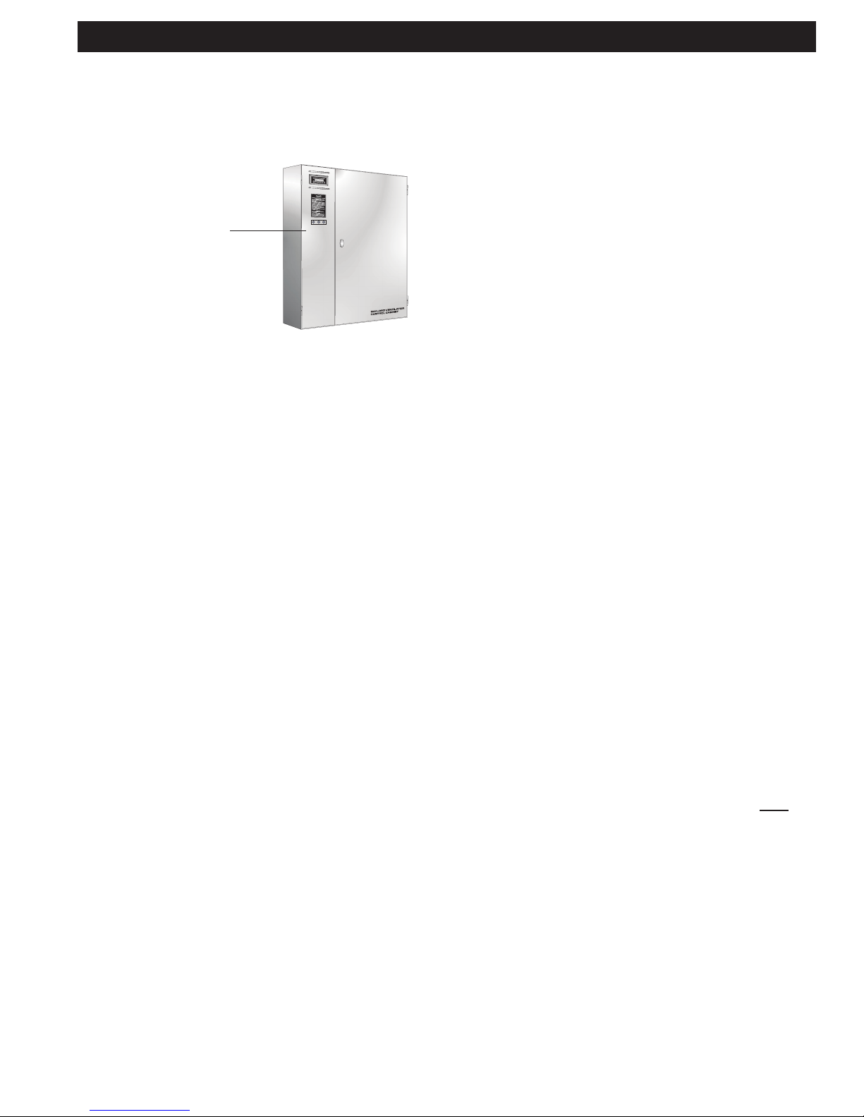
CONTROL CABINET
MODEL GPC-6000-ESP SERIES
DAILY OPERATION
5.After the damper in the ventilator closes to the wash position,
the hot detergent injected water sprays come on to wash away
the grease collected during the day's operation. The wash cycle
stays on for the length of time programmed in the Command
Center. The length of the wash cycle may be set between 3 and
9 minutes.Typical settings for the CG3 Ventilator are 3 minutes
for light-duty equipment, 5 minutes for medium-duty equip-
ment and 9 minutes for heavy-duty equipment. The typical
setting for the ClearAirTM RSPC-ESP unit is 5 minutes. Refer
to page 20 for details on setting the length of the wash.
6. During a Ventilator wash, the digital display reads "Hood
Wash, Wash #1 xxx seconds." xxx is the countdown in
seconds until this portion of the wash is completed.
7. During an ESP wash, the digital display reads:
"ESP Wash 1, Wash #2 xxx seconds"
"Hot Water Heating, Wash #2 xxx seconds"
"ESP Wash 2, Wash #2 xxx seconds."
"Hot Water Heating, Wash #2 xxx seconds"
"ESP Rinse, Wash #2 xxx seconds"
xxx is the countdown in seconds until this portion of the
wash is completed.
8.The digital display now reads "Fan Off 12:00" (current time)
and Start Fan>F1.
After the wash cycle is completed, wipe the exposed front
surface of the damper at the air inlet slot, as well as other
exposed exterior surfaces.
In very heavy cooking operations it may be necessary to
wash the equipment more than once a day. This can be done
manually by pushing the “Start Wash” button.
NOTE: For proper operation of the wash system there must
be adequate water pressure and temperature.There is a pres-
sure/temperature gauge inside the control cabinet.
Water Pressure 60 psi min. - 80 psi max.
Water temperature 160°F min. - 180°F max.
NOTE: Some control cabinets are equipped with a low
detergent switch. If so equipped, the green light will ash if
the detergent tank is empty or if the detergent pump is mal-
functioning and detergent is not pumping. The digital display
reads "Low Detergent" and the text alternates from "Fill Tank"
and "Check Pump". If the detergent tank is lled with water
the detergent switch will activate as if there is no detergent.
NOTE: The wash system is designed to remove daily ac-
cumulations of grease within the equipment. If the equip-
ment is not washed a minimum of once during a cooking
day, a grease buildup could accumulate which the wash
system cannot remove. If this occurs, it is recommended
that the equipment be put through several wash cycles by
pushing the “Start Wash” button on the Command Cen-
ter. If this does not remove the grease, it will be necessary
to remove the grease manually by using a scraping tool,
such as a putty knife, or retain the services of a commercial
hood cleaning service to steam clean or pressure wash
the system.
WARNING: Some commercial hood cleaning services blow a re
retardant chemical into hood and duct systems. Fire retardant chemi-
cals should never be applied to any portion of The Gaylord Ventilator
or ESP unit. If retardant is applied, it must be removed.
COMMAND CENTER
MODEL C-6000 SERIES
DAILY OPERATION
All functions of the Gaylord Ventilator and ClearAirTM Unit, such
as starting the exhaust fan, starting the wash cycle, etc., are
controlled by the Command Center located on the control
cabinet. Refer to Pages 21 through 25 for detailed instructions
on the operation of the Command Center.
20
DAILY OPERATION
Ventilator wash
The length of the ventilator wash is determined primarily by
the cooking equipment involved. Set the wash length from
3 – 9 minutes for light, medium or heavy duty equipment
as shown on the Recommended Ventilator Wash Time
Chart on this page. Adequate cleaning of the Ventilator is
dependent upon water pressure, water temperature, grease
accumulation and hours of operation. It may be necessary
to increase the wash cycle time above recommendations
depending upon these conditions.
ClearAirTM wash
The length of wash cycle time for the ClearAirTM Unit is
normally set for 5 minutes as shown on the "Wash Cycle
Sequence Charts". Set length of ESP washes to 5 minutes.
Delay
The "Wash Delay" is used to set the delay time between
each wash. A delay may be necessary to allow the hot water
system to recover. The Wash Delay may be set from 1 – 99
minutes as required.
Rinse cycle
A rinse cycle is a hot water wash only (no detergent), and
occurs at various times during the wash cycle as shown
on the "Wash Cycle Sequence Charts". The rinse cycle
time is 3 minutes.
TRAHCEMITHSAWROTALITNEVDEDNEMMOCER
TYPE OF COOKING RECOMMENDED WASH
EQUIPMENT TIMES (MINUTES)
LIGHT DUTY ........................................... 3
Ovens, steamers, and kettles
MEDIUM DUTY....................................... 5
Braising pans/Tilting skillets, fryers,
griddles, grooved griddles, open burner
ranges, hot top ranges, and
conveyor ovens
HEAVY DUTY .......................................... 9
Gas and electric char broilers, upright
broilers, woks and conveyor broilers,
Solid fuel broilers
20
DAILY OPERATION
Ventilator wash
The length of the ventilator wash is determined primarily by
the cooking equipment involved. Set the wash length from
3 – 9 minutes for light, medium or heavy duty equipment as
shown on the Recommended Ventilator Wash Time Chart
on this page. Adequate cleaning of the Ventilator is depen-
dent upon water pressure, water temperature, grease accu-
mulation and hours of operation. It may be necessary to
increase the wash cycle time above recommendations de-
pending upon these conditions.
ClearAirTM wash
The length of wash cycle time for the ClearAirTM Unit is nor-
mally set for 5 minutes as shown on the "Wash Cycle Se-
quence Charts". Set length of ESP washes to 5 minutes.
Delay
The "Wash Delay" is used to set the delay time between
each wash. A delay may be necessary to allow the hot wa-
ter system to recover. The Wash Delay may be set from 1 –
99 minutes as required.
Rinse cycle
A rinse cycle is a hot water wash only (no detergent), and
occurs at various times during the wash cycle as shown on
the "Wash Cycle Sequence Charts". The rinse cycle time is
3 minutes.
TRAHCEM I THSAWROT AL I TNEVDEDNEMMOCER
TYPE OF COOKING RECOMMENDED WASH
EQUIPMENT TIMES (MINUTES)
LIGHT DUTY ........................................... 3
Ovens, steamers, and kettles
MEDIUM DUTY ....................................... 5
Braising pans/Tilting skillets, fryers,
griddles, grooved griddles, open burner
ranges, hot top ranges, and
conveyor ovens
HEAVY DUTY .......................................... 9
Gas and electric char broilers, upright
broilers, woks and conveyor broilers,
Solid fuel broilers
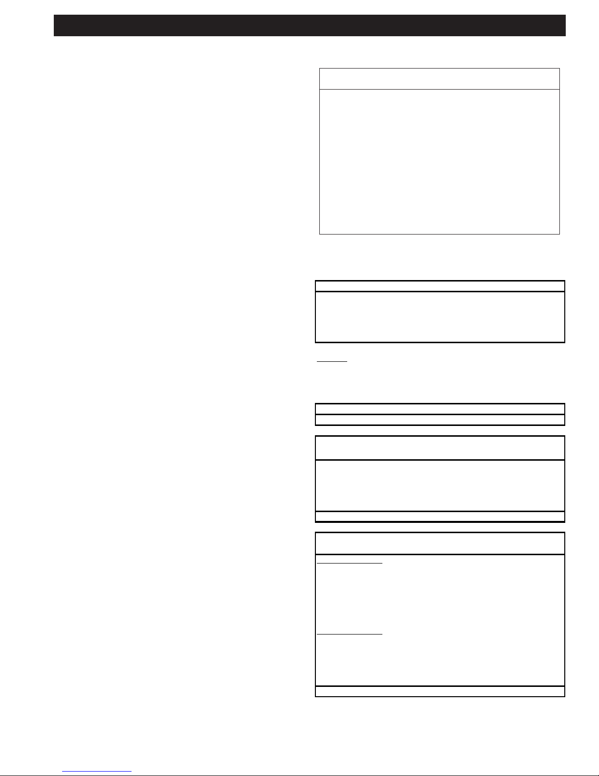
1. ESP Wash 1 (3-9 minutes)
2. Delay (1-99 minutes)
3. ESP Wash 2 (3-9 minutes)
4. Delay (1-99 minutes)
5. ESP Rinse (3 minutes)
NOTES:
* ESP Wash 2 length = ESP Wash 1 length (always)
* ESP Rinse length = 3 minutes (always)
* Please note ALL “Delay” times are the same
1. Hood Wash (3-9 minutes)
1. ESP Wash 1 (5 minutes)
2. Delay (1 minute)
3. ESP Wash 2 (5 minutes)
4. Delay (1 minute)
5. ESP Rinse (3 minutes)
Total Elapsed Time: 15 minutes
Wash Manifold #1
1. ESP Wash 1 (5 minutes)
2. Delay (1 minute)
3. ESP Wash 2 (5 minutes)
4. Delay (1 minute)
5. ESP Rinse (3 minutes)
6. Delay (1 minute)
Wash Manifold #2
7. ESP Wash 1 (5 minutes)
8. Delay (1 minute)
9. ESP Wash 2 (5 minutes)
10. Delay (1 minute)
11. ESP Rinse (3 minutes)
Total Elapsed Time: 31 minutes
Typical Wash Cycle for a Single Pass (1ESP) unit
with 2 Wash manifolds (DW):
All ESP Washes include the followin
g
ste
p
s:
WASH CYCLE SEQUENCE CHARTS
All Hood Washes include the followin
g
:
Typical Wash Cycle for a Single Pass (1ESP) unit
with 1 Wash manifold:
This manual suits for next models
1
Table of contents
Other GAYLORD Air Cleaner manuals


