AtmosAir AtmosSmart 500 Series Technical Document

OUR MISSION
To improve health and wellness by actively restoring indoor air
to its pure, natural state where no pollution or contaminants
exist, while reducing energy use and emissions in the process.
AtmosAir.com
CAG-06-21-003
IMPORTANT
Save this Document
for Future Reference &
Warranty Information
AtmosSmart
Installation, Operation
and Maintenance Guide

Installation, Operation & Maintenance Guide AtmosSmart 2
1-888-MY-AIR11 CAG-06-21-003 AtmosAir.com
Trademarks
Any brand names and product names included in this document are trademarks, registered trademarks, or trade names of their
respective holders.
To the Holder of this Document
The contents of this document are current as of the date of publication. AtmosAir® reserves the right to change the contents
without prior notice.
In no event will AtmosAir be liable for any special, incidental, or consequential damages or for commercial losses even if AtmosAir
has been advised thereof as a result of issue of this document.
WARNING
■Failure to follow this warning could result in personal injury or death.
■Disconnect all electrical power to the air handler before removing access panels or to perform any maintenance activities.
Disconnect power to the AtmosAir units.
■Before installing or servicing system, always turn off main power to system. There may be more than one disconnect switch.
■AtmosAir equipment must be installed with a proper ground. The electrical cable enclosed with your AtmosAir unit must be used
as it has a special plug which provides a ground circuit for the equipment.
■Always replace fuse with the same rating and type of fuse.
■Failure to follow this caution may result in personal injury or product and/or property damage.
■Although special care has been taken to minimize sharp edges in the construction of your unit, be extremely careful when handling
parts or reaching into the unit.
■Keep path clear near and in front of intake screen
■Do not block or obstruct the air ow over or around the ionizing tubes
■Do not touch ionizing tubes when power is on
■Do not operate outside of this range 30°F – 120 °F (-1°C – 49 °C).
■Tube cleaning should be performed only when the power is disconnected.
■The tubes require minimal cleaning with routine operation and maintenance. Longer operating cycles and reduced ionizing
efciency may indicate the need for cleaning or replacing tubes by your AtmosAir dealer or qualied installer.
How to Contact Us: If you need help, please contact an
AtmosAir Representative for technical assistance.
Commissioning Statement
Do not commission new airhandlers after installation. All duct cleaning must be performed before AtmosSmart is installed.

Installation, Operation & Maintenance Guide AtmosSmart 3
1-888-MY-AIR11 CAG-06-21-003 AtmosAir.com
Table of Contents
01 PRODUCT OVERVIEW 5
Bi-Polar Ionization Description 6
General Product Description 6
Mode of Operation 7
02 INSTALLATION 8
03 STEP BY STEP INSTALLATION INSTRUCTIONS 11
Installing AtmosAir 500 Series in a Duct 11
04 MONITORING DISPLAY INSTALLATION 12
05 ATMOSSMART CONNECTION POINTS 12
06 BMS CONNECTIVITY 13
07 ATMOSSMART/ATMOSCOMMS CONNECTIVITY & SEQUENCE 13
08 CONTROL SEQUENCE 14
09 MAINTENANCE REQUIREMENTS 14
10 PRODUCT WARRANTY 15

Installation, Operation & Maintenance Guide AtmosSmart 4
1-888-MY-AIR11 CAG-06-21-003 AtmosAir.com
01 PRODUCT OVERVIEW
APPLICATION
The AtmosSmart ionization system’s sensor head & controller
is intended to be mounted in the return duct or air handler
of a heating, cooling, or ventilating system. The standard unit
simplies monitoring and control of up to eight (8) AtmosAir™
Active Ionization Systems, using BACnet IP Communication.
AtmosSmart
PRODUCT SUBMITTAL
SPECIFICATIONS
Sensor Suite & Test Ranges Sensor Application
Air Quality Sensor 1
(50 - 550 ppm)
Integral - TVOC
(Total Volatile Organic
Compounds)
Air Quality Sensor 2
(0.01 - 4.0 ppm)
Integral - HCHO
(Formaldehyde
Concentration)
Air Quality Sensor 3
(0.5 - 250 µg/m3)
Integral - PM 2.5
(Particulate Matter 2.5)
Humidity Sensor 4
(5% - 95% RH) Integral
Temperature 5
(-10°C to 50°C) Integral
Ozone Sensor 6
(2 -50 ppb) 45 ppb Auto-Shutoff
Carbon Monoxide 7
(0.25 - 2.5 ppm) Integral
Carbon Dioxide 8
(100 - 2500 ppm) Integral
Air Flow Sensor Differential Pressure Switch*
(Optional: Must be Ordered)
Control Capacity
Up to 8 AtmosAir™ Ionization
Systems* Standard Unit (2) BPI
(Requires AtmosMultiplier (4)
with Optional AtmosEXTender)
AtmosAir Solutions™
CAG-05-21-002
1-888-MY-AIR11
AtmosAir.com
Product Ratings
Ambient Temperature -10°C to 50°C
Protection Class 0% - 99%
Non-Condensing
Humidity 0% - 99%
Non-Condensing
Ingress Protection IP4I (DIN EN 60529)
Electrical Safety
Compliance EN 60730-1
EMC Compliance EN 60730-1, EN 61000-6-1, EN
61000-6-3
Directives 2006/95/EC, 2004/108/EC,
2011/65/EU
Electrical Statistics
Rated Voltage 90 to 240 VAC (Auto Switching)
Frequency 50/60 Hz
Voltage Range Control - 5 VDC, Cat5e / Cat6
Power Consumption 12 Watts
Current Draw 2.4 Amps (2,400 mA)
Regulation of BPI Control Algorithm-Based Modulation
Output Current for Modules 5 VDC
Installation Statistics
Required Space [AA508FC]
(L/H/D)
704mm (~27.75”) x 273mm
(~10.75”) x 241mm (~9.5”)
Sensor Head Size
(L/W/D)
305mm (~12”) x 127mm (~5”) x
267mm (~10.5”)
Weight Installation Sensor 1.5kg (~3.3 lbm)
508FC 10.04kg (~22 lbm)
Internet Connection /
Interface
TCP/IP; Optional MSTP
Bacnet IP / BMS HDMI Monitor

Installation, Operation & Maintenance Guide AtmosSmart 5
1-888-MY-AIR11 CAG-06-21-003 AtmosAir.com
Bi-Polar Ionization Description
The internationally certied and patented AtmosAir™
System enables Bi-Polar Ionization at the AtmosAir Ionization
Tubes using controlled electronics. The surrounding oxygen
molecules are ionized, which aid in cleaning indoor air.
General Product Description
AtmosSmart™ is an integrated sensor array designed for
installation in the RETURN duct of a typical HVAC air handling
unit (AHU) system. This array senses air quality by sampling
8 different parameters (see below) in order to control the ion
intensity levels produced by the AtmosAir™ air purication
systems. The system is fully addressable and has two-way
data communication and control capabilities.

Installation, Operation & Maintenance Guide AtmosSmart 6
1-888-MY-AIR11 CAG-06-21-003 AtmosAir.com
Mode of Operation
The AtmosSmart™ Sensor array monitors 8 sensors in its standard conguration: Temperature in °F/°C, Humidity in RH%, TVOC
(total volatile organic compounds), CO (Carbon monoxide), CO2 (Carbon dioxide) which is helpful in determining occupancy, O3
(Ozone), HCHO (Formaldehyde), and PM (Particulate Matter). The IAQ readings can be output by attaching an HDMI capable
display. Display is accessible from a HDMI port located in the Sensor Array body. The display can be placed up to 35’ (10 meters)
away from the sensor array. The HDMI port can output to a Tablet or a remote display (as specied). Longer HDMI runs than 35’ are
achievable with an HDMI repeater. AtmosSmart™ is BMS compatible through BACnet IP and displays real-time Indoor Air Quality
data to BMS.

Installation, Operation & Maintenance Guide AtmosSmart 7
1-888-MY-AIR11 CAG-06-21-003 AtmosAir.com
The Sensor head should be mounted so that it is oriented on the centerline of the return duct with the impeller screen
DOWNSTREAM of the ambient airow, i.e., facing the lter, if present, or the AHU itself.
02 INSTALLATION
The Sensor Array is housed in a doubly insulated hi-impact plastic enclosure which is placed in the duct work or AHU. If placed in
the duct, a 3” × 8” (8 cm × 20.5 cm) rectangular cut-out is made in a typical sheet-metal return approximately 3-4 feet (1.0 – 1.2 m)
downstream from the return lter (if existing). It is recommended, but not required, that the cut-out is usually made in the bottom
of the duct for access/ wiring/ service.

Installation, Operation & Maintenance Guide AtmosSmart 8
1-888-MY-AIR11 CAG-06-21-003 AtmosAir.com
ATMOSSMART
INDOOR
SENSOR
5'(1.5m)
120 OR 240VAC
JCT. BOX
REQ'D
120 OR 240VAC
JCT. BOX
REQ'D
5'(1.5m)
10'(3m)
120 OR
240VAC
EACH
10'(3m)
10'(3m)
120 OR
240VAC
EACH
10'(3m)
10'(3m)
120 OR
240VAC
EACH
10'(3m)
120 OR
240VAC
EACH
35'(10m)
35'(10m)
35'(10m)
120 OR 240VAC
JCT. BOX
REQ'D
5'(1.5m)
AtmosEXTender
SIGNAL AMPLIFIER
35'(10m)
120 OR 240VAC
JCT. BOX
REQ'D
5'(1.5m)
120 OR 240VAC
JCT. BOX
REQ'D
5'(1.5m)
BPI 2
BPI 1
5VDC
10'(3m)
10'(3m)
ATMOSMULTIPLIER 4
508 BPI UNITS ATMOSSMART
CAPABLE CONFIGURATION (8 EXAMPLE)
DO NOT SCALE DRAWING
ATMOSSMART +
ATMOSMULTIPLIER 4 +
AtmosEXTender +
8 BPI EXAMPLE
SHEET 1 OF 1
3/12/21
3/12/21
HG
SB
UNLESS OTHERWISE SPECIFIED:
SCALE: 1:4
WEIGHT:
REV.
A
Created: 3/3/2021
A
SIZE
TITLE:
ATMOSAIR SOLUTIONS
NAME
DATE
PRODUCTION APPR.
ENG APPR.
CHECKED
DRAWN
FINISH
MATERIAL
INTERPRET GEOMETRIC
TOLERANCING PER:
DIMENSIONS ARE IN INCHES
TOLERANCES:
FRACTIONAL
.xxx
ANGULAR: MACH
.xxx BEND
TWO PLACE DECIMAL
.xxx
THREE PLACE DECIMAL
APPLICATION
USED ON
NEXT ASSY
PROPRIETARY AND CONFIDENTIAL
THE INFORMATION CONTAINED IN THIS
DRAWING IS THE SOLE PROPERTY OF
ATMOSAIR SOLUTIONS. ANY
REPRODUCTION IN PART OR AS A WHOLE
WITHOUT THE WRITTEN PERMISSION OF
ATMOSAIR SOLUTIONS IS PROHIBITED.
5
4
3
2
1
Last Saved: 3/12/2021
XXX
XXX
COMMENTS:
XXX
XXX
XXX
JS
As many as 8 AtmosAir BPI units (500 Series and/or Matterhorn Series) can be controlled and monitored via the AtmosSmart™
system. More than one BPI unit being controlled is considered a custom application. The AtmosSmart™ systems are available
in single BPI control or double (two-unit) control, as may be ordered. If more than one BPI unit control is required, then the
AtmosSmart™ must be ordered that way. If more than a two-unit AtmosSmart™ controller is ordered, and additional BPI units are
desired or specied, then a master control box is required which can accommodate up to 8 BPI units per AHU.
Each AtmosSmart™ equipped 508 series/ Matterhorn Series has attached to it a dedicated controller/ communication box (the
module is named ‘AtmosComms2’) that controls the BPI ionization intensity.

Installation, Operation & Maintenance Guide AtmosSmart 9
1-888-MY-AIR11 CAG-06-21-003 AtmosAir.com
The AtmosComms2 module is connected via Cat5e cable to the AtmosSmart™ sensor array.
Warning: Contractor must use the specied AtmosAir Cat5e cable. No substitutions are allowed.
Typically, the 500 Series or Matterhorn Series are either mounted in the supply duct, transition duct, or on racks or mounts
within the Air Handling Unit. Note: See AtmosAir 500 Series or Matterhorn Series IOM for detailed AtmosAir system installation
instructions.
Warning: Verify this is a well-grounded branch dedicated circuit.
All the 500 series BPI systems are wired to dedicated well-grounded 15-amp, 110-125 Vac 50 Hz or 120 Vac 60Hz service via a
dedicated, well-grounded junction box. This circuit should be electrically protected from oating grounds and erroneous voltage
spikes, such as surges and sags.
The AtmosSmart™ sensor array and AtmosComms2 control system derive their operational power from the same main eld wired
circuit providing power to the AtmosAir 500 Series or Matterhorn series. (Refer to warning note above).
The sensor head reads multiple indoor air quality (IAQ) data-sets in real time by sensing air properties in the Return Air system.
This conguration allows the sensor to adjust IAQ based on demand, observing contaminants, humidity, and occupancy every few
seconds.
The Bi-polar Ionization power, ionization output and duration are based on these readings and decisions made using AtmosAir
proprietary algorithms. Bandwidth decision time, algorithms and operational parameters are tailored and customized in AtmosAir
facilities to the nal customer’s application.
Typically, every 30 seconds, an average of readings is taken. As the AtmosSmart sensor is read, that value goes into an AtmosAir
proprietary algorithm. Every (2) minutes the ‘decision engine’ makes a go/no-go evaluation based on pre-programmed set points.
Three ‘decisions’ are made within one standard air exchange. Every 6 minutes, AtmosSmart performs an ‘air exchange calculation.’
A coarse debris screen is installed on the impeller sensor port. The internal fan in the AtmosSmart™ Sensor Array assures
continuous metering and sampling of the air and the space in front of the screen should not be obscured or restricted. The sensor
should not be subjected to condensing moisture nor temperatures exceeding the range of 30 °F to 120 °F (-1 °C to 49 °C).

Installation, Operation & Maintenance Guide AtmosSmart 10
1-888-MY-AIR11 CAG-06-21-003 AtmosAir.com
03 STEP BY STEP INSTALLATION
1. Determine centerline of return duct and or transition return duct, mark centerline.
2. Mounting locations shall be at least 4 feet or 1.25 m from lters, obstructions, re sensors, turning vanes or dampers.
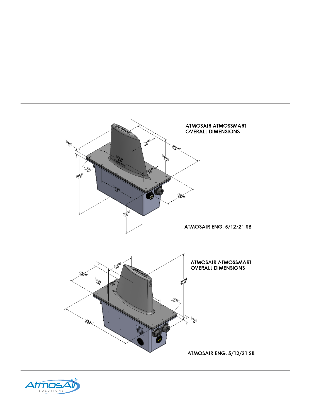
3. The AtmosSmart™ aerodynamically shaped sensor head is designed to protrude through any internal insulation typically
found in a HVAC system, and allow a clear unimpeded path so that air can ow to and inside the sensor head.
4. Cut a 3” wide by 8” long (8 cm × 20.5 cm) rectangular slot in the bottom of the duct centered along the duct centerline.
5. It is permissible to cut an 8” long slit in the Fiberglas insulation matting within the duct. Alternately, the full size 3” × 8” (8 cm ×
20.5 cm) rectangular slot can be cut in the insulation.
6. In an EXTERIOR insulated duct, the insulation must be removed from a 6” wide × 13” (15cm × 33cm) long area on the marked
installation centerline.
Warning: This insulation must not interfere with cabling, receptacles, and metering fan airow from Sensor.
7. Attach the Sensor array using the 6 self-tapping screws provided.
8. Assure that the sealing gasket provided is seated securely so that the space between the tower and the duct is sealed and not
leaking. Do not overtighten more than is necessary to seal the gasket.
9. If installing an outside air probe, the air inlet, pictured in the illustration must be facing in towards the incoming outside air.
The probe can also be placed within the outside air plenum if accessible.
Installing AtmosAir 500 Series in a Duct
Note: Refer to the 500 series (or Matterhorn Series) IOM Manual for typical installation recommendations.
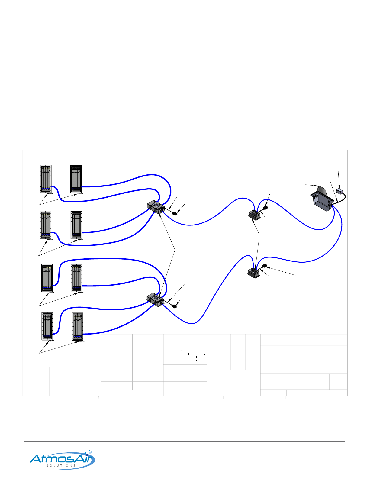
Each AtmosSmart™ enabled 500 series / Matterhorn Series unit has an AtmosComms2 controller module integrally installed. These
controller modules communicate with the sensor array and other 500 series units within the particular AHU in which they are
installed. To provide power to the BPI units as well as the sensor array, each 500 series and/or Matterhorn Series, unit has a 120 Vac /
240 Vac (nominal) power umbilical that should be connected to a dedicated 15-amp well- grounded service.
All AtmosSmart™ sensor arrays have a 120 V/ 240 V, 50/60 Hz small ‘brick-type’ transformer to provide stable, unuctuating power
to the unit’s internal computer. This transformer is provided with a standard plug suitable for the region/country in which the
AtmosAir system is to be installed. This can be dedicated to the same, well-grounded, 15-amp service to which the AtmosAir BPI
systems are connected.
Each 500 series/AtmosComms2 has a RJ-45/Cat5e receptacle in its casework; each unit shall be connected, using the cable
provided, to the input/output (I/O) connector for 1 and 2 BPI systems/arrays.
The I/O master controller module, Multiplier 4 (handling up to 8 BPI systems), may be mounted within the AHU, on its wall or
ceiling. The main Cat5e addressable cable will need to be run through the air handler wall; the wall is usually double thick 2” (5 cm)
and the hole can be formed utilizing a .75” (20 mm) drill. The pass-through hole should be sealed with a suitable sealant such as
silicone or mastic, at both walls of the AHU, running to the AtmosSmart™ Sensor.
The main addressable Cat5e cable from the I/O controller box, AtmosEXTender, may be no longer than 35’ (10.2 meters) and is to
be plugged into the port on the AtmosSmart™ sensor array. A run longer than 35’ requires am HMDI repeater for proper system
performance. It is recommended that that communication cable is secured via ‘P’ clips every 1 m.

Installation, Operation & Maintenance Guide AtmosSmart 11
1-888-MY-AIR11 CAG-06-21-003 AtmosAir.com
04 MONITORING DISPLAY INSTALLATION
AtmosSmart™ IAQ Data HDMI to Monitor Display Option: A 4” × 7” (10 cm ×
18 cm) optional remote display is supported (but not supplied). The Raspberry
Pi 4 can be mounted in close proximity to the AtmosSmart™ sensor array at the
bottom of the duct. A mounting bracket is optional. The display shows real-time
data and is read-only. It may be folded up out of the way. A HDMI port is also
provided in the Sensor Body. A large remote monitor can also be powered from
this HDMI receptacle. While there is no length dimension on this HDMI cable,
33’ (10 meters) is recommended. For longer cable routing, a HDMI repeater is
required. Below are the 8 data points that the AtmosSmart system records, that
can be displayed via an optional Monitor:
05 ATMOSSMART CONNECTION POINT
BACNET / NETWORK END
BPI END

Installation, Operation & Maintenance Guide AtmosSmart 12
1-888-MY-AIR11 CAG-06-21-003 AtmosAir.com
06 BMS CONNECTIVITY
AtmosSmart is BMS compatible through BACnet IP. Ethernet connection is made from the AtmosSmart system to the BMS using
RJ45/Cat5E cable. There are eight (8) BMS read points per AtmosSmart™ controller. (see list mentioned earlier) The AtmosSmart™
displays Real-Time IAQ Data to BMS. Optional AtmosAir also offer an optional outside air probe to read the incoming outside air.
This can be connected to BMS using RJ45/ Cat5E cable (not supplied) AtmosAir also offers an optional BMS Remote On/Off Control
of the AtmosAir BPI systems.
07 ATMOSSMART/ATMOSCOMMS CONNECTIVITY & SEQUENCE
NOTE: The two ends with receptacles of the AtmosSmart Sensor Probe are generally arranged as ‘network’ and ‘display’ on one
end, and output to AtmosAir BPI Systems and Micro-USB on the other. If the AtmosAir BPI control cable is plugged into the wrong
RJ-45 cable receptacle nothing will happen. Check for the correct RJ-45 receptacles.
Note/Warning: All power must be off to both ends of the AtmosSmart System and AtmosAir BPI System. Once the two ends of the
AtmosSmart/AtmosAir BPI system are installed/mounted, the installer should connect the following cables.
1. Main power Armorex shrouded umbilical to 120 VAC to 250 VAC 50/60 Hz 15-amp dedicated service with known good ground
via junction box. Umbilical is 10’ (3.05m) long. (Check to see main toggle switch is off).
2. Connect the supplied ethernet cable between the jack on the AtmosSmart unit to the AtmosComms2 controller.
Note: This is the only jack on the AtmosComms2 system mounted under the ionizer that could receive this cable.
3. If you are connecting a second AtmosAir/AtmosComms2 to a single AtmosSmart, there is another RJ-45 Cat5e cable to connect.
(See photos in AtmosSmart Capable Conguration Diagram).
4. Connect the Micro-USB ‘brick-type’ power supply to the same 15-amp dedicated as the AtmosAir system(s). This is to power the
AtmosSmart module.
5. Connect HDMI cable to display (optional).
6. Connect RJ-45 port to network/BMS. Cable not supplied.
Power-Up and Commissioning
AtmosSmart derives its power from the main Armorex umbilical. Assure there is power to the unit(s).
Switch on main power toggle switch on AtmosAir 500 Series BPI system and the AtmosSmart IAQ probe. The AtmosSmart will
automatically go into a 6-minute self-check and sensor warm up mode. The output display will indicate that it is self-checking and
warming up the sensors.
The display will start scrolling real time data after about 6 minutes. You may not see any indication of AtmosAir System operation
immediately.
Within 6 plus minutes the AtmosAir systems will start cycling and setting its parameters.
You will know the AtmosAir system is responding to AtmosSmart commands by the red function light on the AtmosAir BPI unit
which will periodically cycle on or off according to demand.
When AtmosSmart is sensing and making air quality ‘decisions’ it is possible that the AtmosAir system’s red light may remain off
for up to 30 seconds. The unit will self-start or re-start when the power is lost and regained.

Installation, Operation & Maintenance Guide AtmosSmart 13
1-888-MY-AIR11 CAG-06-21-003 AtmosAir.com
09 MAINTENANCE REQUIREMENTS
In addition to the routine maintenance that you perform, your AtmosAir system should be inspected regularly by a properly
trained service technician.
Your annual system inspection should include:
■Routine inspection of the ionizing tubes and clearance around the intake screen along with replacement or cleaning as required
■Inspection and cleaning of the AtmosAir ionizing tubes
■Removal of obstructions of loose materials in the ducts
■Check all electrical wiring and connections
■Check for secure physical connections of individual parts in each unit
■Operational check of the ionization system to determine actual working condition. Necessary repair and/or adjustment should be
performed at this time.
■The sensor array is designed to be maintenance-free for years and is calibrated at the factory.
■There are no user serviceable parts inside the sealed Sensor module.
■Sensors will need to be replaced & recalibrated generally after 2 calendar years.
■Certied AtmosAir dealers will coordinate sensor maintenance. AtmosAir dealers will provide temporary calibrated units while
AtmosSmart is being serviced at the AtmosAir factory. This is accomplished with a ‘hot-swap’ of AtmosSmart sensor heads while
units are being serviced.
■The only other maintenance required is assuring that the AtmosSmart™ sensor probe’s impeller screen is not obstructed, and that
the metering fan is running.
■AtmosDongle may be employed to provide BPI function during calibration of AtmosSmart.
08 CONTROL SEQUENCE
■Every 30 seconds, an average of readings is taken. As the AtmosSmart™ Ozone (O3) sensor is read. That value goes into a
proprietary algorithm.
■Every 2 minutes the ‘decision engine’ makes a go/no-go evaluation based on AtmosAir set-points. If the value is below that limit the
BPI unit will restart.
■Every 6 minutes, AtmosSmart™ performs an ‘air exchange calculation’. Should the limit be reached within that time frame, the BPI
unit(s) will go off again.

Installation, Operation & Maintenance Guide AtmosSmart 14
1-888-MY-AIR11 CAG-06-21-003 AtmosAir.com
y
y
CLEAN AIR GROUP, INC. – PRODUCT WARRANTY
Clean Air Group, Inc. d/b/a AtmosAir Solutions (“Clean Air Group”) warrants to the original purchaser of this product (“Customer”),
that should it prove to be defective by reason of improper materials or workmanship, for twenty-four (24) months from the date
of installation, or twenty-seven (27) months from the date of Clean Air Group’s delivery of the product, whichever occurs first,
Clean Air Group shall repair or replace the product without charge to the Customer. Proof of malfunction and return of the non-
working product must be presented by the Customer if submitting a warranty claim. This warranty is invalid if the factory applied
serial number has been altered or removed from the product. This warranty does not cover damage due to acts of God, misuse,
abuse, negligence, or modification of or to any part of the product. This warranty does not cover damage due to improper
installation, operation or maintenance, connection to improper voltage or electrical supply, or repair by anyone other than an
authorized Clean Air Group service provider. To obtain warranty service the Customer must: (1) provide proof of purchase in
the form of a Bill of Sale or receipted invoice, with evidence that the product is within the warranty period; (2) request a Return
Merchandise Authorization (“RMA”) from Clean Air Group prior to shipping; and (3) ship the product with the RMA to Clean Air
Group, freight prepaid, in either its original packaging or packaging affording an equal degree of protection. The product should
be delivered to AtmosAir, 2115 East Cedar Street, Suite 6, Tempe, AZ 85281. All transportation charges and shipping expenses
are the Customer’s responsibility. Clean Air Group will return the product by the same method it receives the product. A product
returned for repair after the warranty period, or that shows damage outside of the warranty coverage described herein, shall be
repaired for a reasonable charge as determined by Clean Air Group. The Customer will be advised of the cost of repair or
replacement before Clean Air Group proceeds.
THE OBLIGATIONS OF CLEAN AIR GROUP HERIN ARE EXPRESSLY GRANTED IN LIEU OF ALL WARRANTS, WHETHER
EXPRESS OR IMPLIED, INCLUDING BUT NOT LIMITED TO IMPLIED WARRANTIES OF MERCHANTABILITY AND FITNESS
FOR A PARTICULAR PURPOSE. ALL IMPLIED WARRANTIES INCLUDING WARRANTIES OF MERCHANTABILITY AND
FITNESS FOR PARTICULAR PURPOSE ARE LIMITED TO THE TERM OF THE EXPRESS WARRANTY GRANTED HEREIN.
Some states do not allow limitations on how long an implied warranty lasts, so the foregoing limitation or exclusion may not apply
to you.
With the exception of damages resulting from Clean Air Group’s failure to comply with any obligation under federal or state
warranty laws, Clean Air Group SHALL NOT BE LIABLE TO THE CUSTOMER OR ANY OTHER PERSON OR THIRD PARTY
FOR ANY DAMAGES, INCLUDING BUT NOT LIMITED TO CONSEQUENTIAL, SPECIAL, INDIRECT, INCIDENTAL AND
PUNITIVE DAMAGES AND/OR DAMAGES BY REASON OF INJURY TO ANY PERSON DUE TO ANY DEFECT OR
MALFUNCTION OF THE PRODUCT OR ANY PART OR PARTS THEREOF OR FOR ANY OTHER REASON. This warranty
gives you specific legal rights and you may have rights which vary from state to state. If your product is defective please contact
Clean Air Group or the dealer where you purchased the unit.
Disclaimer: The air purification technology provided by AtmosAir is intended to improve air quality. It is not intended to replace
reasonable precautions to prevent the transmission of airborne contaminants. Customer, its employees, invitees and all persons
having access to the serviced premises should comply with all applicable public health laws and guidelines issued by federal,
state and local governments and health authorities such as the Centers for Disease Control and Prevention (CDC). These
precautions include but are not limited to wearing face masks, social distancing, hand hygiene and appropriate sanitizing and
disinfecting. Clean Air Group does not assert that its products can protect people from viruses, bacteria or other airborne
contaminants, expressly excludes liability for loss or damage arising from any such claims, and does not assume any liability for
the consequences arising out of the application, use or misuse of its products, including any injury or damage to any person or
damage to any property as a matter of product liability, negligence, contract or otherwise.
Manufacturer,
Anthony M. Abate
Chief Technology Officer
Clean Air Group, Inc.
10 PRODUCT WARRANTY
This manual suits for next models
1
Table of contents
Other AtmosAir Air Cleaner manuals

AtmosAir
AtmosAir 700 series User manual

AtmosAir
AtmosAir 500 Series Technical Document

AtmosAir
AtmosAir T400 Guide

AtmosAir
AtmosAir 500 Series Technical Document

AtmosAir
AtmosAir Rainier Summit R1 Instruction manual

AtmosAir
AtmosAir Matterhorn 880 Technical Document

AtmosAir
AtmosAir FC-100 Series Technical Document

AtmosAir
AtmosAir P2000 User manual

AtmosAir
AtmosAir P2002 User manual

AtmosAir
AtmosAir FC-400 Series Technical Document