GBC Ricoh StreamPunch Pro User manual

Ricoh StreamPunch Pro, Pro EX & MP Installation Manual 1
Ricoh StreamPunch™Pro, Pro EX & MP
Installation Manual
Contents Page
1. Recommendations and Pre-requisites 2
2. Unpacking 2
3. Cable Connections 2
4. Installing the Sound Deadening Foam 5
5. Docking Bracket Installation 7
6. Leveling & Height Adjustment 8
7. FinalSteps 9
Part No. 7712832
Rev No. K1
1 Issue Date: April 11, 2014
ACCO Brands, Inc.
Four Corporate Drive
Lake Zurich, IL 60047
www.acco.com

Ricoh StreamPunch Pro, Pro EX & MP Installation Manual 2
1. Recommendations and Pre-requisites
•You will need the installation kit provided with the StreamPunch unit, which can be found in the
main carton.
•If installing the StreamPunch downstream from a BK5000 Booklet Maker, a cover kit is required.
(Part No US – 404282EDP, EU – 961462EDP, AUS – 7708997)
•Using a jogging unit on the finisher will improve the stack quality for binding purposes.
•If installing the StreamPunch directly downstream of Pro C900 series, Pro C651/C751 EX or Pro
C751, contact your local service representative to obtain the correct entrance guide.
2. Unpacking
•Inspect the outside of the package for shipping damage. If there is evidence of shipping damage,
contact the shipping carrier immediately.
•Remove the punch from its shipping carton. Three people are recommended, one lifting at the
casters while two lift at the top cover. DO NOT lift using the front door panel.
•Retain the smaller accessory box; it contains parts required for correct installation of the
StreamPunch.
•Inspect for any concealed damage to the unit. If there is evidence of concealed shipping damage,
contact the shipping carrier immediately.
•Remove all shipping tape from doors and levers.
3. Cable Connections
Review the table below to identify which section of the guide to refer to install the StreamPunch Pro/
Pro EX/ MP.
Section Printers Finisher
3.1 Pro C900 series, Pro C550/700 & MPC6501/7501 SR5000
3.2 MP6001/7001/8001/9001 SR4050
3.2 MP6002/7502/9002 SR4080
3.3 Pro 907/1107/1357EX SR5020
3.3 Pro C651 EX & Pro C751 EX SR5030/ SR5040
3.3 MP C8002/ C6502 & Pro C5100S/ C5110S SR4110
3.3 Pro 8100S/8110S/8120S SR5050/ SR5060
Refer to the following section when installing the SK5010 downstream of the StreamPunch Pro.
3.4 High Capacity Stacker SK5010
3.1 SR5000 Finisher
The cables below are required to attach the StreamPunch Pro to this type of finisher.
Finisher to StreamPunch cable Finisher to printer cable (longer version)
p/n VR340046 p/n VRC57001

Ricoh StreamPunch Pro, Pro EX & MP Installation Manual 3
a)
Remove the finisher rear
cover and plug the 7 pin
communication cable to
CN144 in the bottom left
corner of the SR5000
finisher board.
b)
Replace the finisher to
printer cable with the
longer cable provided.
Plug the 8 & 9 pin
connector’s into CN100 &
CN101 on the finisher
board. Replace the
finisher rear cover.
c)
Plug the free end of the
cable from step a) into the
right side of the
StreamPunch. Plug the
free end of the cable from
step b) into the connector
on the printer.
d) There are two entrance paper guides provided with the StreamPunch. Use the longer paper guide
measuring about 14” long when used in conjunction with the SR5000 finisher. Install the paper guide,
using the size #8 screws provided, to the lower entrance guide of the StreamPunch.
If installing the StreamPunch directly downstream from the printer, contact your local service
representative to obtain the correct entrance guide.
Go to Section 4 to complete the installation.

Ricoh StreamPunch Pro, Pro EX & MP Installation Manual 4
3.2 SR4050 & SR4080 Finisher
Follow the same steps as in 3.1 but in step a) connect the 7 pin connector into CN138 on the finisher
board.
d) There are two entrance paper guides provided
with the StreamPunch. Use the shorter paper
guide measuring about 12” long when used in
conjunction with the SR4050 finisher. Install the
paper guide, using the size #8 screws provided,
to the lower entrance guide of the StreamPunch.
Go to Section 4 to complete the installation.
3.3 SR5020, SR5030, SR5040, SR5050, SR5060 Finishers
Follow the same steps as in 3.1 but in step a) connect the 7 pin connector into CN110 on the finisher
board.
d) There are two entrance paper guides
provided with the StreamPunch. Use the
longer paper guide measuring about 14” long
when used in conjunction with the SR5020,
SR5030 or SR5040 finishers. Install the
paper guide, using the size #8 screws
provided, to the lower entrance guide of the
StreamPunch.
If installing the StreamPunch directly downstream from the Pro C651/C751 EX or Pro C751, contact
your local service representative to obtain the correct entrance guide.
Go to Section 4 to complete the installation.
3.4 SK5010 High Capacity Stacker
Follow the same steps as in 3.1 but in step a) connect the 7 pin connector into CN150 on the finisher
board and in step b) replace the shorter finisher to printer cable with the longer one provided,
plugging the 8 pin cable in to loose connector and the 9 pin into CN101 on the finisher board.
There are two lower exit guides that can be used with the StreamPunch. The standard 90 degree
bend is used for most configurations and comes ready installed. When the SK5010 is installed
directly downstream from the StreamPunch, the angled guide shown below should be fitted in place
of the 90 degree guide. The angled exit guide is provided with the installation kit.
Standard 90
degree exit guide
Angled
exit guide
Lower exit
guide

Ricoh StreamPunch Pro, Pro EX & MP Installation Manual 5
4. Installing the Sound Deadening Foam
Supplied with the StreamPunch, you will find six
strips of sound deadening foam are shipped loose
for field installation. These are not attached at the
factory to avoid compression and/or damage
during shipping.
To install, simply peal the back off to reveal the
adhesive using the following steps as a reference.
4.1 Paper Exit Side (Finisher Side)
Apply the wide strip to the right side as
shown.
Apply one of the two shorter pieces to the
side of the top cover as shown.

Ricoh StreamPunch Pro, Pro EX & MP Installation Manual 6
Apply one of the three longer strips to the left
rear panel as shown.
Exit side complete
4.2 Paper Entrance Side (Printer Side)
Apply one of the two remaining long strips to the
right side of the printer side of the StreamPunch
as shown.
Apply the last remaining short strip to the top
cover edge of the printer side of the StreamPunch
as shown.
Apply the last remaining long strip to the left side
of the printer side of the StreamPunch as shown.

Ricoh StreamPunch Pro, Pro EX & MP Installation Manual 7
5. Docking Bracket Installation
The docking brackets are shipped in a
separate bag along with size M4
mounting screws (not shown). There
are 2 lengths supplied. You may need
to use the longer screws for some
printers when installing without the
buffer pass unit. The brackets have a
number 2 stamped in the bottom
corner.
Install as shown with the bracket
marked “R” on the right side facing
you as you look at the exit side of the
upstream device. Install the bracket
marked “L” on the left side facing you.
Both brackets should be oriented with
the arrow facing up.
Before the system can be docked
correctly the paper guide on the
finisher needs to be removed. This is
not used on the finisher when in line
with the StreamPunch.
The docking bracket(s) provided with
the finisher should be attached to the
downstream side of the StreamPunch
with 4 size M4 screws.

Ricoh StreamPunch Pro, Pro EX & MP Installation Manual 8
6. Leveling & Height Adjustment
6.1 Height Setting
No height adjustment of the StreamPunch is required, for an installation site with a level floor, when
docking upstream of the SR4050, SR5020, SK5010 or SR5030. If the floor is uneven then it is
recommended to set the level of the StreamPunch using the downstream device as a reference. The exit
guide of the StreamPunch should be set as shown below for the various finisher types. When installing
the StreamPunch upstream of the SK5000, the StreamPunch will need to be lowered by approximately
5mm. Follow the same adjustment procedure as in Section 6.2 and use the table below for a reference
height.
Finisher Reference Height X Finisher Reference Height Y
SR5000 4mm SK5010 2.5mm
SR4050/SR4080 4mm
SR5020 3mm
SR5030/ SR5040 3mm
SK5000* 2.5mm
* Height adjustment required
6.2 Adjusting the Casters
a)
Using a 9/16” (15mm) open ended wrench, loosen
the jam nut(s) situated on the caster stud inside of
the machine.
b)
Using the 9/16” (15mm) wrench, rotate the caster
stems to change the height.
Re-tighten the jam nuts once the correct height is
achieved.
X
StreamPunch
Output
Downstream
Device Input Downstream
Device Input StreamPunch
Out
p
ut
Y

Ricoh StreamPunch Pro, Pro EX & MP Installation Manual 9
7. Final Steps
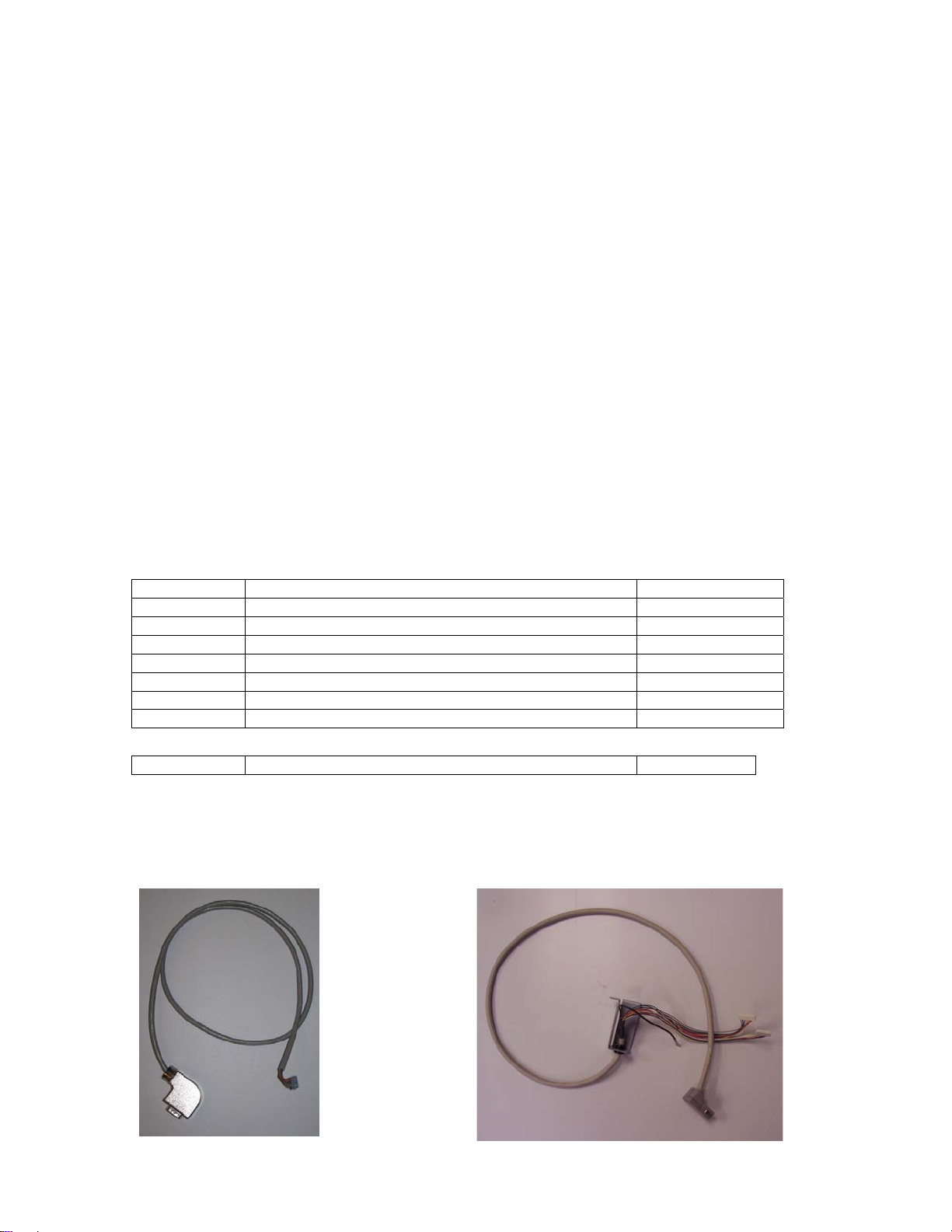
7.1 Printer & Finisher Firmware
Confirm that the printer and finisher have the latest firmware installed. Firmware is available for download
at www.tscweb.net (US) or www.ricoh-support.com/techuser/ (EU) or can be obtained by contacting
Ricoh service.
Special custom engine firmware must be installed if installing the StreamPunch with the Martini-C4 (MP
6001/7001/8001/9001).
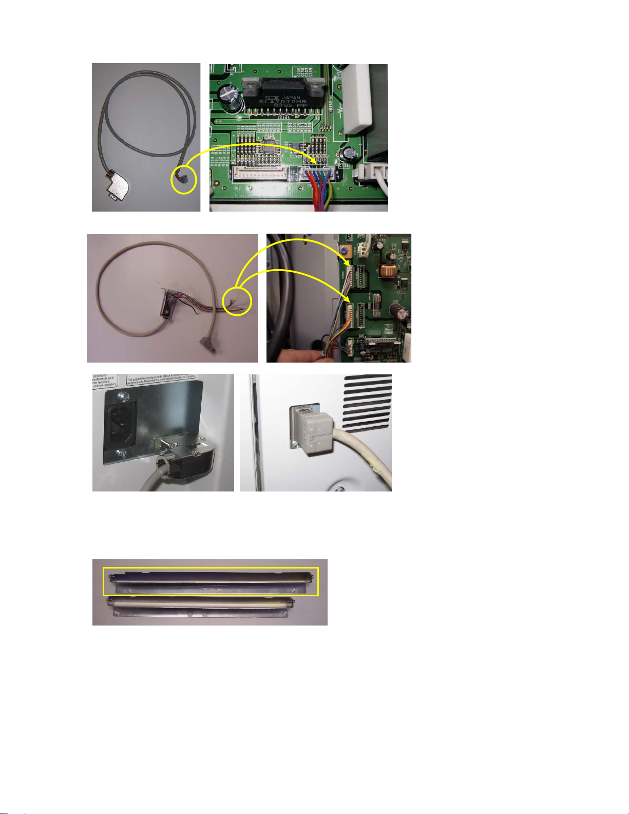
7.2 Setting the Dip Switch
If the unit is fitted with a dip-switch then the setting should be changed depending on the printer it is
attached to. If present, the dip-switch is located next to the firmware upload connector on the rear cover.
If the dip-switch is not present then no setting is required. Set the dip-switch per the table below.
Dip Switch Setting
Printe
r
1
2
3
45678
Pro 907/1107/1357EX OFFONONONONONONOFF
Pro C900 series OFF ON ON OFF OFF ON ON OFF
Pro C550/700, MPC6501/7501 OFF ON ON ON OFF ON ON OFF
MP6001/7001/8001/9001 OFF ON ON OFF ON ON ON OFF
Pro C651/751 EX, Pro C751 OFF ON ON ON ON OFF ON OFF
MP6002/7502/9002 OFF ON ON OFF ON ON OFF OFF
MP C8002/ Pro C5100s OFF ON ON OFF ON OFF ON OFF
Pro 8100S/8110S/8120S OFF ON ON OFF OFF OFF ON OFF
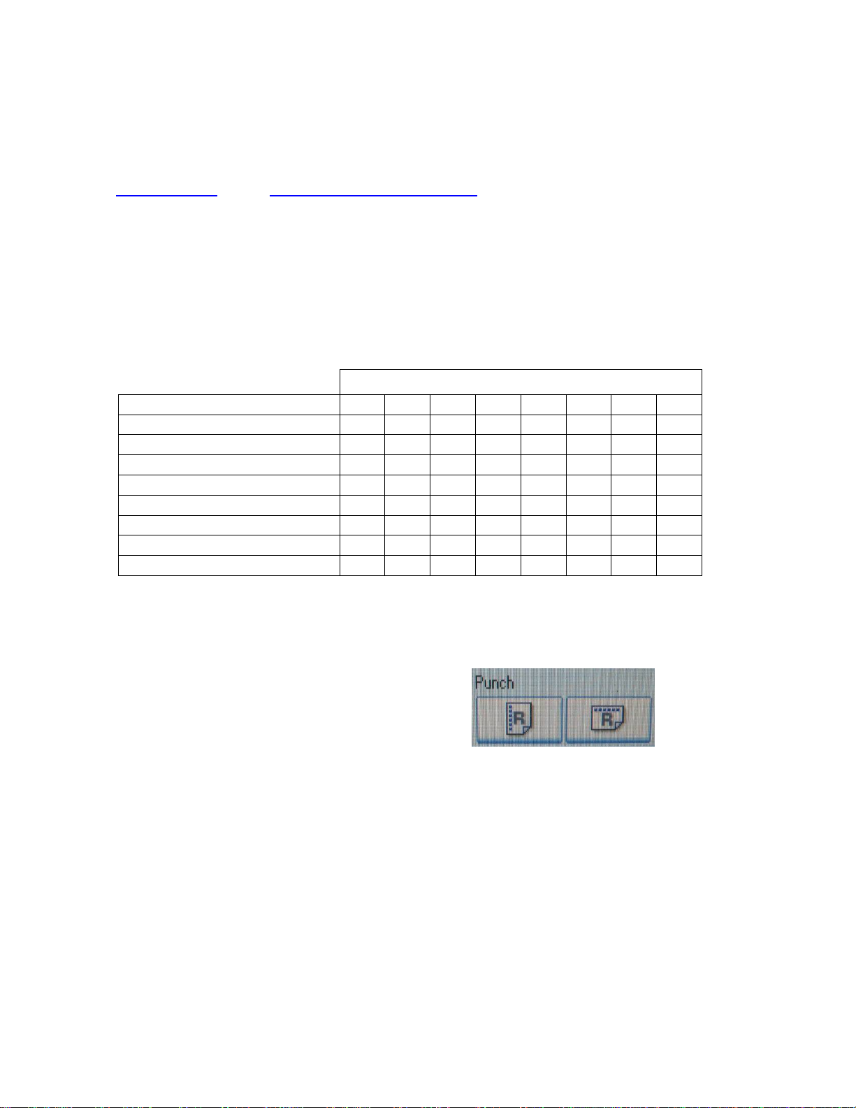
7.3 Enabling the Punch Icon
If the punch icon (shown below) for the Stream Punch option does not appear on the operation panel,
follow the procedure below:
a) Select User Tools
b) Select Copier/Document Server Features
c) Select Input/Output Tab
d) Select Punch Type-Top Option
e) Select Item-one on the left
f) Select Punch Type-Multiple Hole: Left
g) Exit
Note: If the punch option will not enable due to paper size or direction, change the Original Orientation
(lower left corner of the copier Operation Panel).
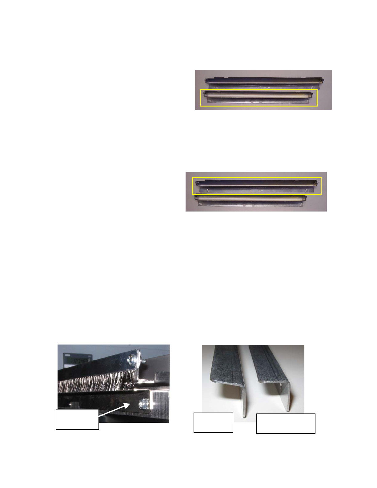
7.4 Functional Test
Functional test the StreamPunch system
a) Check to ensure that the paper chip tray is securely in place.
b) Check to ensure that a die set is installed properly and that any extra die sets are securely stored in
the die storage area.
c) Run a small test job in “Bypass” mode. Check to ensure that the job is not punched and bypasses
properly.
d) Run a small job with punch enabled. Check the punched holes of the job.
e) Run each die set to punch 100 sheets or until there is no oil residue around the holes.
This manual suits for next models
2
Table of contents
Other GBC Printer Accessories manuals