Casanoov RANGER B150 User manual

RANGER B150
INSTRUCTION MANUAL / NOTICE DE MONTAGE / MONTAGEANLEITUNG / MANUAL DE MONTAJE / MANUAL DE MONTAGEM / MANUALE DI MONTAGGIO / MONTAGEHANDLEIDING / INSTRUKCJA MONTAŻU
EN FR DE ES PT IT NL PL
STI-000022
STW-000022
EN
FR
DE
ES
PT
IT
NL
PL
The manual should be read prior to beginning installation and keep after
Le manuel doit être lu avant de commencer l’installation et conservé après
Das Handbuch sollte vor Beginn der Installation gelesen und nach der Installation aufbewahrt werden.
El manual debe ser leído antes de comenzar la instalación y mantenerlo después
O manual deve ser lido antes do início da instalação e mantido após
Il manuale deve essere letto prima di iniziare l’installazione e conservato dopo
De handleiding moet voor het begin van de installatie worden gelezen en na de installatie worden bewaard
Instrukcję należy przeczytać przed rozpoczęciem instalacji i zachować ją po
CAUTION / ATTENTION / ACHTUNG / ATENCIÓN / ATTENZIONE / AANDACHT / UWAGA
!

EN
FR
DE
ES
PT
IT
NL
PL
3
20
37
54
71
88
105
122
Manual translated from English version using automatic translator. In case of question please refer to english version.

EN
3
CAUTION
• This product must be installed by well-trained skilled personnel in compliance with the safety
regulations the field of residential and commercial swing gate opener devices.
Unqualified personnel may damage the instruments and cause harm to the public.
• Electric Power must be disconnected prior to installation, or performing any maintenance.
• Please read the manual carefully before installation. Incorrect installation or misuse of product
may cause seriously damage to users and property.
• If the electric cable is damaged or broken, it must be replaced by a whole and properly insulated
wires, to avoid electric shock or any hazardous environments.
• Keep the wireless transmitters out of children reach.
• Do not allow children or other individuals to stand by the path of the motor arms or the path
of the gates while in operation.
• Do not use the remote wireless transmitters when the gates are out of sight.
• Do not install the products in corrosive, inflammable, and/or explosive environments.
• Avoid installing the motor arm where the override manual release key is exposed to the public.
!

EN
4
x2 x1 x1 x4 x2
x2 x2 x2 x8 x2
x2 x4 x2 x4 x4
(Required) (Required) (Required) (Required) (Required)
(Required) (Required) (Required) (Recommended)
Tools Required
K L M N O
A B C D
F G H I J
E

EN
5
Serial Number

EN
6
Product overview
Max single vent weight : 150 KG
Environment Temperature : -45°C ~ +50°C
Protection Class : IP55
Max gate open angle : 110 degree
Rated capacity : 2090N
Maximum rated capacity : 2190N
Dual Swing Gate automation’s Gross weight : 13KG
Motor voltage : 24VDC 40W
Input power : 220VAC±10%/110VAC±10%
Rotational speed : 200 RPM
Arm’s extended speed : 1.6 cm/s
Arm’s max travel : 300 mm
Continue running time : 5 minutes
Max single vent length : 2 meters
44 mm33 mm
58 mm
33 mm
90 mm
800 mm
350 mm 455 mm 255 mm
1060 mm
Technical specifications

EN
7
1
33
44
6
2x1,5mm2
RX - 4x0,5mm2
2x1,5mm2
TX - 4x0,5mm2
2x1,5mm2
3x1,5mm2
Open the gate manually : Release by spanner then lift it.
Gate
Manually spanner
Release by spanner then lift it and separate the motor from gate
1
2
3
Manual unlocking
Swing Gate automation Features & Options
Flash lamp
Control box
Photo cells
1
2
3
4
5
6
1
2
3
2
3
Swing gate opener motor
Remove auto-close and keep the central stop
Remote control
2
F
C
5

EN
8
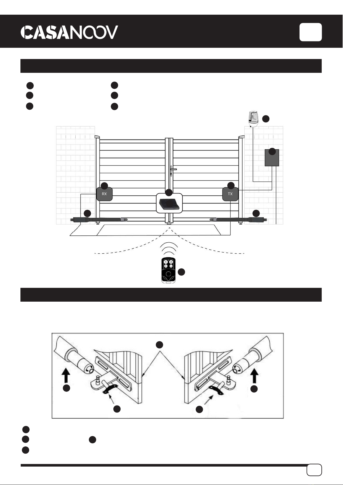
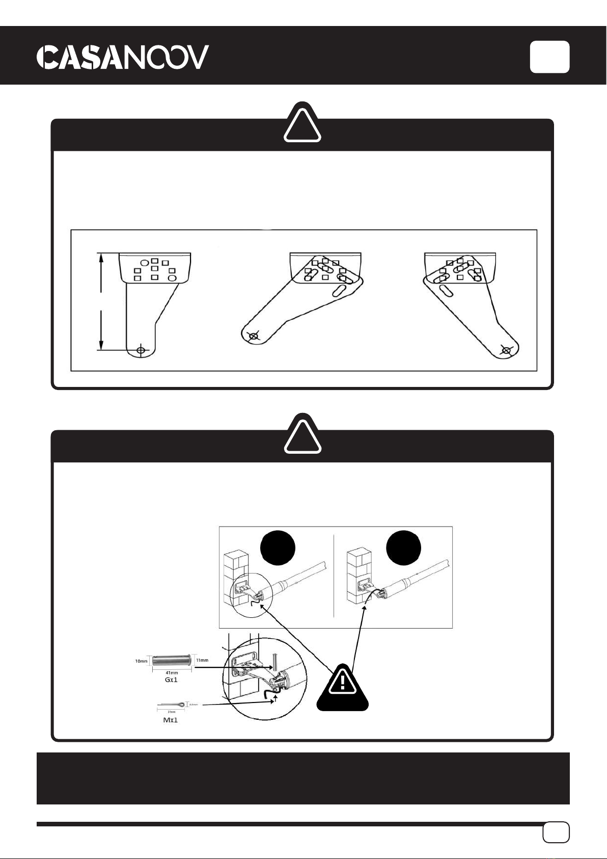
Drill 4 Holes of 8mm Diameter.
Insert the 4 Provided Bolts for
concrete or brick and Tighten
Properly (Do not over tighten as
you may strip the bolt out of the
concrete or the brick). Rref I x 4.
Place the Motor Connecting
Bracket and Tighten with the
Provided Screws. Ref. O x 2.
A
B
C
•When Gate is Obstructed : Gate stops.
•Optional : The Gate Opener Controller can be connected to a solar system, a Flash light warning, a photocell, back up battery, keypad
and other access control devices.
•Speed Control : Gate opening and closing speed can be adjusted.
•Gentle Start : The Gate Opener is equipped with a soft start function.
•Auto Close : The Gate Opener System is equipped with Auto close function with adjustable closing time delay.
•Single or Dual Gate : Either Single or Dual Swing Gate can be opened.
•Multiple Remote Transmitters : The Controller can easily accommodate several unique extra remotes to control the swing gate opener.
•Battery Back Up : DC 24V back up battery can be incorporated
•Optional Devices : DC 24V Gate Lock, photocell ,keypad , photocell, push button, large size or small size control box.
The Gate Opener can be configured to allow smooth noiseless operation.
The Gate Opener can be configured to enable open condition as default, or close condition as default depending on the placement of the
provided hardware brackets.
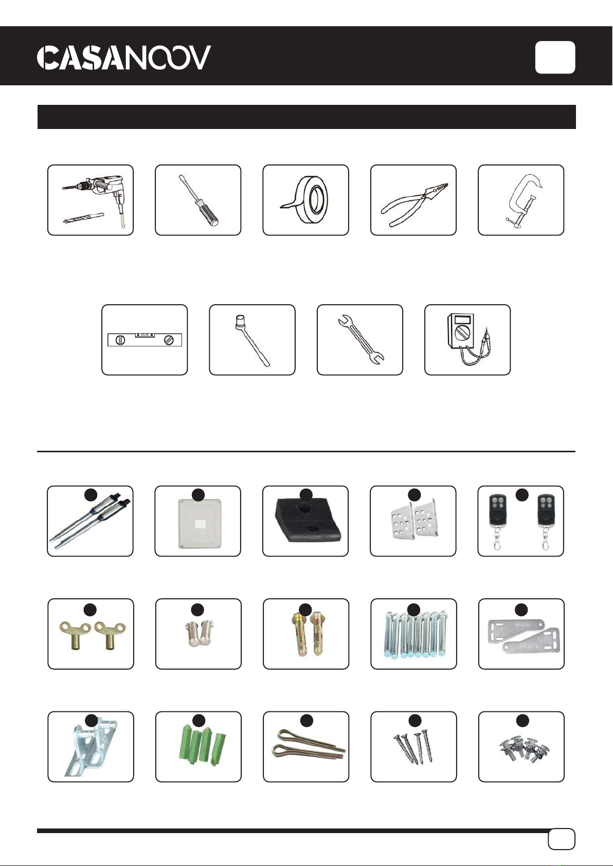
General options and accessories
Construction Drill and Bolts
Dx2
0x2
Jx1
Ix4

EN
9
CABLE MUST NOT BE INSTALLED ABOVE THE MOTOR ARM.
IT MAY PINCH AND STRIP THE CABLE AND CAUSES ELECTRIC SHOCK.
WARNING
Adjusting different angles of Rear Bracket Fixed Plate to fit different Installing condition.
WARNING
Fixing motor on bracket. Watch that the electric cable is in the proper position !
181.5mm
!
!
OK KO
WARNING

EN
10
Installation of Extended End Motor Arms to Gates
Before installing : extend the motor’s arm to its maximum size then retract inside
around 1cm.
Ensure that the Post bracket height is in the same exact level with the gate bracket
height.
Failing to ensure accurate common heights will cause the motor arm to bend leading to
failure. Also, the force to push or pull the gate will be reduced causing the motor to open
or close the gates with difficulty or may not operate successfully at all. Severe different
in height will damage the motor and the motor arm.
USE BUBBLE LEVEL
K
D
Extended arm - 1 cm
!

EN
11
Drill 2 Holes of 10.2mm Diameter With Space 68 to 77 mm Between 2 holes.
Locate the 2 Slotted Holes Gate Bracket above the Drilled Holes.
Place the End Motor Bracket to the Gate Bracket using the Appropriate Bolts and Tighten Properly.
Please note these bolts used to fixed front bracket to the gate are not provided due to the thickness
of each gate is different.
Insert the Lock Pin and Clamping Washers ref. F
A
B
C
D
Installation size : you can adjustment the gate degree according to these numbers
Installation of Motor’s Arms to Gates

EN
12
1
2
3
4
5
6
7
8
9
10
11
12
13
14
15
16
17
18
19
21
23
24
25
26
27
28
29
SIDE terminal is used for connecting any external device that operates double gate.
COM terminal is COMMON used for connecting the “ground” of external devices.
SIDE terminal is used for connecting any external device that operates single gate.
Swipe Card terminal is used for connecting any external devices that will operate to
open the gate.
COM terminal is COMMON used for connecting the “ground” of external devices.
Infrared terminal is used for connecting photo electric sensor.
12V DC output is used for connecting photo electric sensor (Continuous output cur-
rent <=200mA).
24V battery output is used for connecting the back up battery +.
24V battery output is used for connecting the back up battery -.
24V DC output is used for connecting external device. (such as photo electric sensor,
max current output 1A).
GND is used for connecting the “ground” of external devices.
24V DC lamp output is used for connecting flash light +.
24V DC lamp output is used for connecting flash light -.
24V DC lock output—the NF terminal which used for connecting the electric lock.
COM is COMMON used for connecting the “ground” of lock.
24V DC lock output—the NA terminal which used for
connecting the magnetic lock.
24V DC alarm output.
Motor1 terminal is used for connecting the motor 1 installed
on the gate that opens later and close first. This terminal
connect 1st red wire (from your left hand side to right hand
side).
Motor2 Delay terminal is used for connecting the motor 2
installed on the gate that opens first and close later. This ter-
minal connect 1st blue wire ( from your left hand side to right
hand side). NOTE! If for single gate, the gate motor just can
connect the Motor2 Delay terminal.
AC24V input is used for connecting the transformer.
Digital display is used for showing you the setting data.
INC+ is used for figure increase when setting the data.
FUN is used for recorde the data.
DEC- is used for figure decrease when setting the data.
Learning button is used for program/remove remote.
Control board wiring diagram
1 2 3 4 5 6 7 8 9 10 11 12 13 14 15 16 17 18
19
20
20 21
22
22
2324
25
26 27 28
29

EN
13
TURN OFF ELECTRICY BEFORE CONNECTING THE CONTROL BOARD
TO THE 230V AND TO ACCESSORIES.
123 4 5 6 7 8 9 10 11 12 13 14 15 16 17 18 19 21
20 22
25 26
2 side and 1 side are for connect
open device, such as push but-
ton, wired keypad, camera video,
GSM controller etc...
!

EN
14
-
+
IR
+-
+
-
IR
--
+
+
+
+-

EN
15
Button “1” depressed to operate single gate;
Button “2” depressed to operate double gate;
Button “3” depressed for alarm output
Program new remote control:
> First step
Press the LEARN button on the control board [29] for about 1 second, the indicator LED would turn off,
then now means have already enter learning Second step:
Press any button of the new remote control for about 2 second, then digital display would show the
remote number while indicator LED on board starts flash four times with one buzzer sound then now
means the learning successfully.
Note! After you press LEARN button, if not receive the new remote signal within 5s, indicator LED would
turn on and exit learning. Remove remote control:
Press and hold the LEARN button for about 5 second, if with one buzzer sound and indicator LED light
on, then now means remove remote successfully.
After power on, digital display will self-check from 00-99 with buzzer sound. If indicator LED light on,
buzzer stop sound, it means the system is normal.
Basic operation method:
Press and hold the [ FUN] button until the digital display shows PO. Now you enter the menu setting.
You could through adjust the [INC+] [DEC-] to increase or decrease the serial number or numerical
value. After data adjust well then press [ FUN] to store the data. With one sound of buzzer, the store
successfully.
After store the data, the digital display would still on the menu number you just set, if you need to enter
next menu setting, please press [INC+] or [DEC-] to choose and confirm with [FUN] to enter the menu
number you want to set. Such as after you store the P0 value and press [FUN] to store it, then now the
digital display would still show the number P0, and if you want go further to adjust P1, please press one
[INC+], then digital display show P1, later press [FUN] to enter the P1 setting.
If you not need to enter next menu setting, you could press [LEARN] button to exit the menu setting.
Remote control
Setting of the control board

EN
16
MANUAL
SETTING
FUN RANGE
SETING
P0 Soft start time setting 0-6 s 2 s SOFT START
P1 Motor 1 low speed running stall
force adjustment.
0-20Level 6th Level Ml LOW OVER
LOAD
P2 Motor 1 high speed running stall
force adjustment.
0-20Level 10th Level M1 HI OVER
LOAD
P3 Motor 2 low speed running stall
force adjustment.
6th Level 10th Level M2 LOW OVER
LOAD
P4 Motor 2 high speed running stall
force adjustment.
0-20Level 10th Level M2 HI OVER LOAD
P5 To set the high speed running time 0-33s 5s HI-SPEED
P6 To set the auto close time after
swipe card
0-99s 10s CARD-CLOSE
AUTO CLOSE
P7 To set the Interval time on opening
the door
0-10s 0(close) OPEN DELAY
P8 To set the Interval time on closing
the door
0-10s 0(close) CLOSE DELAY
P9 To set auto close time 0-99s 0(close) AUTO CLOSE
PA To set lamp alarm output control 0
PB To set lock 0-2s
PC Button of remote selection 0-3 3
PD To choose photocell work en NC or
NO
0-1 1(NC)
PE To choose single/double gate open 0-1 0(Double)
PO RESET 0-1 0(Double) RESET

EN
17
1. To set the soft start time:
When digital display indicate P0, the gate opener
is on the soft start time setting. The soft start time
adjustable from 0-6s, 0s means close the soft start
time, max soft start time 6s. Each time you press and
release the [INC+] button, the figure increase by 1;
each time you press and release the [DEC-] button,
the figure decrease by 1. Press the [FUN] button to
store the data when the soft start time chosen, then
the soft start time setting finished (Factory set 2s).
2. To set the level of stall force:
When digital display indicate P1, the gate
opener is on Motor 1 low speed running stall force
adjustment. There is 0-20 levels for optional, each
time you press and release the [INC+] button, the
figure increase by 1; each time you press and release
the [DEC-] button, the figure decrease by 1. Press the
[FUN] button to store the data when the stall force
level chosen, then the stall force of Motor 1 low speed
running stall force adjustment finished. (factory set 6
level)
When digital display indicate P2, the gate ope-
ner is on Motor 1 high speed running stall force ad-
justment. There is 0-20 levels for optional. Each time
you press and release the [INC+] button, the figure
increase by 1; each time you press and release the
[DEC-] button, the figure decrease by 1. Press the
[FUN] button to store the data when the stall force
level chosen, then the stall force of Motor 1 high
speed running stall force adjustment finished. (fac-
tory set 10 level)
When digital display indicate P3, the gate
opener is on Motor 2 low speed running stall force
adjustment. There is 0-20 levels for optional. Each
time you press and release the [INC+] button, the
figure increase by 1; each time you press and release
the [DEC-] button, the figure decrease by 1. Press
the [FUN] button to store the data when the stall
force level chosen, then the stall force of Motor 2 low
speed running stall
force adjustment finished. (factory set 6 level)
When digital display indicate P4, the gate ope-
ner is on Motor 2 high speed running stall force ad-
justment. There is 0-20 levels for optional. Each time
you press and release the [INC+] button, the figure
increase by 1; each time you press and release the
[DEC-] button, the figure decrease by 1. Press the
[FUN] button to store the data when the stall force
level chosen, then the stall force of Motor 2 high
speed running stall force adjustment finished. (fac-
tory set 10 level)
3. To set the high speed running time: 11
When digital display indicate P5, the gate opener is
on high speed running time setting. There is 0-33s
for optional. 0s means without high speed running,
gate opener would keep running in slow speed. Max
high speed running time 33s. Each time you press
and release the [INC+] button, the figure increase by
1; each time you press and release the [DEC-] but-
ton, the figure decrease by 1. Press the [FUN] button
to store the data when the high speed running time
chosen, then the high speed running time setting fi-
nished. (factory set 5s)
4. To set the auto close time after swipe card:
When digital display indicate P6, the gate opener is
on auto close time setting ( NOTE! this auto close
time just means the auto close function which realize
through external device-). There is 0-99s for optio-
nal. 0 means the gate opener would not auto close
after swipe card. Max auto close time after swipe
card 99s. Each time you press and release the [INC+]
button, the figure increase by 1; each time you press
and release the [DEC-] button, the figure decrease
by 1. Press the [FUN] button to store the data when
the auto close time after swipe card chosen, then the
auto close time after swipe card finished. (factory set
10s)
5. To set the interval time:
5a. When digital display indicate P7, the gate ope-
ner is on open interval time setting. There is 0-10s
for optional. 0s means double gates open simul-
taneously. “1” means the Motor 1 start to open 1 se-
cond before Motor 2 start to open. Max open interval
time 10s. Each time you press and release the [INC+]
Setting of the control board

EN
18
button, the figure increase by 1; each time you press
and release the [DEC-] button, the figure decrease
by 1. Press the [FUN] button to store the data when
the open interval time chosen, then the open interval
time setting finished. (factory set 0s)
5b. When digital display indicate P8, the gate opener
is on close interval time setting. There is 0-10s for
optional. 0s mean double gates close simultaneously.
“1” means the Motor 2 start to close 1 second before
Motor 1 start to close. Max close interval time 10s.
Each time you press and release the [INC+] button,
the figure increase by 1; each time you press and
release the [DEC-] button, the figure decrease by 1.
Press the [FUN] button to store the data when the
close interval time chosen, then the close interval
time setting finished. (factory set 0s)
6. To set auto close time:
When digital display indicate P9, the gate opener is
on auto close time setting. There is 0-99s for optio-
nal. 0s mean the gate opener would not auto close.
Max auto close time is 99s. Each time you press and
release the [INC+] button, the figure increase by 1;
each time you press and release the [DEC-] button,
the figure decrease by 1. Press the [FUN] button to
store the data when the auto close time chosen, then
the auto close time setting finished. (factory set 0)
When digital display indicate PA, the gate opener is
on lamp/alarm output control setting. There is 0-3
for optional. “0” means the alarm on monostabillity
model and the lamp without voltage output after
the gate total close 30s, other time with voltage 12
output. “1” means the alarm on monostabillity mo-
del and the lamp would only flash when gate run-
ning. “2” means the alarm on bistabillity model and
the lamp without voltage output after the gate total
close 30s, other time with voltage output. “3” means
the alarm on bistabillity model and the lamp would
only flash when gate running. Each time you press
and release the [INC+] button, the figure increase by
1; each time you press and release the [DEC-] button,
the figure decrease by 1. Press the [FUN] button to
store the data when the auto close time chosen, then
the lamp/alarm output control setting finished. (fac-
tory set 0)
8. To set lock time:
When digital display indicate Pb, the gate opener is
on lock time control setting. The lock control time
means the time we could control the lock. There is
0-1 for optional. “0” means the lock control time is
0.5s, “1” means the lock control time is 5s. Each time
you press and release the [INC+] button, the figure
increase by 1; each time you press and release the
[DEC-] button, the figure decrease by 1. Press the
[FUN] button to store the data when the lock control
time chosen, then the lock time setting finished. (fac-
tory set 0)
When digital display indicate PC, the gate opener is
on single/double gate open setting. There is 0-3 for
optional. “0” means the gate could not open by re-
mote, “1” means just can open one single gate, “2”
means can just open two leaf gate, “3” means can
open one single gate as well as two leaf gate. Each
time you press and release the [INC+] button, the fi-
gure increase by 1; each time you press and release
the [DEC-] button, the figure decrease by 1. Press
the [FUN] button to store the data when the single/
double gate open chosen, then the remote button
setting finished. (factory set 3)
When digital display indicate Pd, you could choose
the photocell work in NO or NC.
Value 00 means work in NO, value 01 means work in
NC.
11. To reset:
When digital display indicate Po, the gate opener is
on rest setting. After enter Po setting, press the [
FUN] to store and then now the reset successfully.

EN
19
Hoortrade SAS
4 bis avenue jean françois raclet 69007 lyon France
Declares that the following product/
SKU : PKM-C01-L – HOORTRADE reference : STI-000022
Satisfies the essential requisites established in following directives :
EN 60335-1 :2012+A11 :2014+A13 :2017+A1 :2019+A14 :2019
And satisfies the following standards :
EN 55014-1 :2017
EN 61000-3-2 :2019
EN 61000-3-3 :2013+A1 :2019
EN 55014-2 :2015
EN 61000-4-5 :2009+A1 :2017
EN 61000-4-6 :2014/AC :2015
EN 61000-4-11 :2019
« manufacturer also declares that it is not permitted fot the abovementioned components to be used
such time as the system in wich they are incorporated is declared conform to European directive.
Any modification made on the machine without our prior acceptance is making this declaration not va-
lid. »
Main technical caracteristics :
Motor voltage: 24VDC 40W.
Input power:220VAC±10%/110VAC±10%
Rotational speed: 200 RPM.
Arm’s extended speed: 1.6 cm/s.
Arm’s max travel: 300 mm.
Continue running time: 5 minutes
Max single vent length: 2 meters
Max single vent weight: 150 KG
Environment Temperature: -45°C ~ +50°C
Protection Class: IP55
Max gate open angle: 110 degree
Max peak N: 2190
Serial number : 2020/06/00001 to YYYY/MM/xxxxx
Name of signator :
Position :
Signature :
Declaration of CE conformity
Technical report number : DL-2020030542E / DL2020030546S

FR
20
ATTENTION
• Ce produit doit être installé par un personnel qualifié et bien formé, en conformité avec les
règles de sécurité en vigueur dans le domaine des dispositifs d’ouverture de portails à battants
résidentiels et commerciaux. Un personnel non qualifié peut endommager les instruments et
causer des dommages au public.
• L’alimentation électrique doit être déconnectée avant l’installation ou l’exécution de toute
maintenance.
• Veuillez lire attentivement le manuel avant l’installation. Une installation incorrecte ou une
mauvaise utilisation du produit peut causer de sérieux dommages aux utilisateurs et aux biens.
• Si le câble électrique est endommagé ou cassé, il doit être remplacé par un ensemble de fils
correctement isolés, afin d’éviter tout choc électrique ou tout environnement dangereux.
• Gardez les émetteurs sans fil hors de portée des enfants.
• Ne laissez pas les enfants ou d’autres personnes se tenir sur le chemin des bras moteurs ou
sur le chemin des portails lorsqu’ils sont en fonctionnement.
• N’utilisez pas les transmetteurs sans fil à distance lorsque les portails sont hors de vue.
• N’installez pas les produits dans des environnements corrosifs, inflammables et/ou explosifs.
• Évitez d’installer le bras du moteur à un endroit où la clé de déverrouillage manuel de secours
est exposée au public.
!
Other manuals for RANGER B150
1
This manual suits for next models
1
Table of contents
Languages:
Other Casanoov Gate Opener manuals

Casanoov
Casanoov TANKER B250 User manual

Casanoov
Casanoov TANKER B350 User manual

Casanoov
Casanoov VOGEL 500C140 User manual

Casanoov
Casanoov TANKER B250 User manual

Casanoov
Casanoov HICKER B200 User manual

Casanoov
Casanoov RANGER B150 User manual

Casanoov
Casanoov VOGEL 500C160 User manual

Casanoov
Casanoov RANGER C300 User manual

Casanoov
Casanoov TANKER C600 User manual

Casanoov
Casanoov EIGER 500C160 User manual