gdw SETGDWSP 2 User manual

Available for use only with negative earth and 12V battery
voltage. :.
ffi_*
Device complying with Directive 95154lCE (e9 02-4348).
This wiring kit can be installed on most passenger cars or commercial vehicles,
including vehicles that have:
I A digitally controlled light system with mixed voltages.
I Lamp failure detection system. (SFL)
I BSI multiplexed wiring system.
I Fog light activation system.
I CAN BUS Data system.
I Low voltage detection system.
I Check-Control
I Light switching system.
Available Íor use only in vehicles with negative earth and +1 2V battery voltage.
This device cannot be used on vehicles with reverse polarity (positive goes t0 the
chassis or body) or in vehicles with battery voltages other than +1 2V.
This kit prevents any Íailure or overload , and is designed to connect power directly
from the vehicle battery or alternator, avoiding possible Íailures in the vehicle control
u nit.
This product has a 2 year guarantee against possible manuÍacturing deÍects. The
guarantee does not cover damage caused by misuse 0r inconect installation, such
as installation of the kit in vehicles with reverse polarity or subjecting this kit to
other voltages than +12V Any tampering with the product, such as opening the
circuit box will also lead to cancellation 0f the guarantee.
G0lll nv
Hngnolenwegd 23lB 8790 Wanlen.Belgíun
Tel : +32(0)56/60 42 12 Fu +32(0)56160 0l 93
Rel ll' : 002
Date apÍoi: 07-0$2011

ÈK
I QuÍck connection in the electronic module.
I Possibility oÍ disconnecting the pDC (parking sensors).
I C2 syslem: detects malÍunctioning of Ílashing lights and position lights on
the trailer by emitting a sound signal.
I Additional channel Íor vehicles with fog lights activated by earth.
I Replacement function oÍ Ílashing lÍght for position light in case oÍ lamp Íailure
of the Ílashing light on the trailer.
I Complete disconnection or reduction of intensity of one 0r two fog lights.
I Compatible wÍth trailers or caravans with one or two Íog lights.
I ln switch (not as an ampliÍier) check loads in Íigures.
REF. I}escription Pill 0llht Replacelneil
conneclion lighlÍunc.lion Poc t2
disconnedion
to0 light
dhconnection
SEIGDI,VSP 27 PIl,l 7 YES YES
lfs
ÏES
YES
TES
YES
YES
Its
S[TGDWSP13_2 UniwÍsalwiring lrit l3Pt[l 1g iES
à<ÍDIAGRAM 2 KIT SETGDIIYSPí3 2 MAXI -í3 Pr{l
GDIï nY
H000n0lenwe0el 23lB 8790 l//atr;lr;n.Bdliun
Tdt i$2A56160 42 t2 til: +npwi 0t W
Rev ll': 002
Dalearub: 07-0$2011

à<
C(lMP(lTIETITS SUPPLIEO SETGDWSP-z SEÍGDWSP13-2
13 pin 12N socket with 13-wire 'l,5m cable
Screws M5x35 3
M5 Nuts
washers 5
Red electrical connector-shunt 15
Yellow electrical conneclorshunl
Blue electrical connector-shunt
6 m red oower cable + 1 m white cable
5m red power cable
3-wire 3m cable brown,
cable Íor
Fuse holderwith 154
1
SelÍ-adhesive Íastener
I nstallation instruction/manual
iOmcemstraps g I
Terminal 8 mm
buzer
[wire cabte Íoi buzer/parktronic
4-wire cable
à<í TNSTALLATION INSTRUCTIOI{S
1. BeÍore you begin, read the installation instructions careÍully and check iÍ all
components are supPlied.
2. Make sure that the circuits are disconnected, isolated and saÍe to start work,
always Íollowing the instructions provided by the vehicle manufacturer.
3. The circuit has to be supplied Írom an independent power point on the car using
sections that are suited to the maximum consumption oÍ the trailer and always
placing the fuse holder as close as possible to the battery 0r power source'
4. Place the socket holder (7 PIN) 03 PIN) on the socket holder oÍ the tow bar and
run the 7-wire cable to'the inside of the vehicle in order to connect with the
module. Fasten the cable io the tow bar with the cable straps.
G0Í{ nY Rer ll": 002
DateaDÍot: 07{$2011
HngÍnlen[f{/d 23lB 87W fiuegen'Belltun
Td : +32(0)fi160 42 12 Fa +32(0)5il6fr 0l 93

rl
I
l
i
li
ti
ii
DK
S'Connect the white earth wire with the terminar to an earthing point in the vehicre,
make sure rhe connection is crean ano-iióó';ïï;;r;'"""
6' Connect the wires with the red erectrical connector-shunts to the wiring oÍ the
vehicte's tisht units. Connecr two sioe risÀi;, jiËrt,jilïiànt, the Íos tisht and
both Írashins rishts or indicators. rn óátJàiih, ïiïi.ï r,ii ., s pin a connecti'n
oÍ the rear light is also needed. - ' - - !' rr r.v rul
7. This wiring kit has an additional3_wire_cable (2,3m) (green, brown, blue) in case
there has to be made a connection.on the oïher ód;;iiÀ, vehicle. ThereÍore
remove the 3 pins (sreen, n1ow1, trqg) i, tnï ipiíii,Jrieï and reptace rhem by
the tong wire placing the colours on tf,'e same póiliion."""
'È
-/ ---=-3=-
c@9 ,' --
i,Í "
ii
IF THE CABLE IS TOO SHORT, THEN USE CABLE X
t ifllffillf t 6-wire cable in the I pin socket anached to the vehicte, Íoilowins
9' Attach the modure 'ETGDWS'-2 with the serf-adhesive part n Q , to the vehicre
on a drv and ventirared orace. Àvoio ienid; r;rhil;Ë; betueen rhe modure
and the light units.
1 0. Bring the fuse (1 54) in the fuse horder, attach this one to the red cabre connected
to the power source. Check ir everytninsli t;;;;;i;à: ""
. Ailention: BeÍore you place the s.cket of the trailer or caravan on the tow bar vou
have to make sure rhat al lorrs or the traiiàr;Ë;#;ï;ï;riliil;i;s:ïiil;
use a_v.onase.searchins dóvÍce oiódË;ffiï;il;i, check rhe correcr
G'nnecri'n, prease keep in mind rhar.sód à-rrii,àï -ritilt give Íarse readings
31,ï yi;ïflrlrï;:lr'#e nr' use a resr i n s b ói nÏ i cï i Ín i'ï;iÁ rn e co nsu-m pr'i ii
3
G0ll/ ntt
H0 0gn \hnwe I 23E BI
g0 W
ar ljtlj
n- Bet\i t1n
tet : +32(0)56/60 42 t2 ra,': +3i(0)56/6ó 0i 93
Rev l{': 002
0ale aní0i: 07.09-201 1

à<
. For vehicles equipped with the replacement lighting system (e.g. iÍ a sidelight
bulb Íuses, the brake light performs this Íunction), it is necessary that all buibs
of the vehicle work properly, so the lights on the trailer will also work.
. Further it is nec€ssary to also have the lights of the trailer or caravan in peÍect
condition, in order to prevent that the electronic module of the wiring kit aitivates
a wrong lamp when the indicators are disconnected or in case oÍ lamp Íailure.
.The installer has to place the electronic module so it is protected Írom water or
moisture, since it has inside a little signal to detect iÍ the trailer is connected or
not. The signal might wrongly interprete contact with water as the trailer being
connected, while this is not the case.
. lnstaller and customer both have to make sure that the consumption oÍ trailer
clearance and side lights is well distributed in the two channels and there is no
overload in either of the channels that could cause damage to the module.
DIK specnl cAsEs
. Multiplexed syslem: when there are two Íunctions on one lamp (e.g. sidelight
and brake light or sidelight and Íog light) both wires covering inàsà tunctions
(sidelight and brake light or sidelight and Í09 light) have to be ionnected on the
same wire. The module will recognlze the difÍerence between both functions.
. C2 (WARNING LAMP FAILURE): The module SEIGDWSP_2 version MMI detects a
lamp Íailure oÍ a flashing light or sidelight by emitting a warning beep, in case oÍ the
flashing light the sound signal is transmitted on the Írequence oÍ the íashing light, in
case oÍ,the sidelights you each time hear the sound signal Íor some time when you turn
0n the lights. lÍ a lamp on the Ílashing light 0Í the trailer has a Íailure, the Íunction ls
replaced by the lamp oÍ the sidelight.
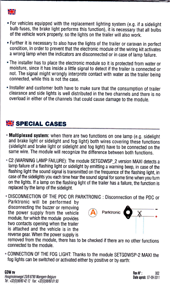
. DISC0NNECTION 0F THE PDC 0R PARK|RON|C : Disconnection oÍ the pDC or
@ na*tronic0l, ;
removed from the module, there has to be checked iÍ there are no other Íunctions
connected to the module.
. CONNECTION 0F THE FOc LIGHï Thanks to the modute SETGDWSP-2 MMt rhe
Íog lights can be switched or activated either by positive or by earth:
0DlY nv
HoognolnwEel 23/8 87ffi ,i/arÍ;len-Eírlgiun
Tel : +32(0)56fi0 a2 fl tu: +32(0)5il60 0l fi
Parktronic will be perÍormed by
disconnecting the buzzer or removing
the power supply from the vehicle
module, Íor which the module provides
two contacts opening when the trailer
is attached and the vehicle is in the
reverse gear. When the power supply is
ReY ll': 002
0rlr a0Í!b: 0t0$2011

à<
. 0PTl0N 1" Íog light activated by positive.
. 0PTl0N 2": Íog light activated by earth. ln that case we take the incoming
signal (blue wire) from position 4 to position I by pushing on the contact with
a fine point to make the wire coming out of the socket. To ensure that the signal
also reaches this position you have to turn on the beam lights before you place
backthesocket. _{c-l
M=
AGTTvATED I I AGTIvATEIBY
By posrTtvE T i EARIII (llEGATlvE)
Ëtnl
I
ffi 40
. DISC0NNECTI0N 0F THE FOG LIGHTS: At the connection oÍ the Íog lights has to be
checked whether the connection point to the vehicle is compatible with the socket oÍ
the trailer. Since the module switches automatically between the voltages it is important
to veriÍy iÍ no Íailures are generated when the Íog lights are connected.
suilTGHrilG 0F FoG $GTH (0PTr0[]
PWM: SIDELIGHTS AND FOG LIGHT HAVE THE
SAME CABLE PWM
To cut lhe sideliohh in the Íog light
IMPORTA]IT
. The maximum voltage of 15V cannot be surpassed.
. Maximum load on the exits is 64.
. The total maximum voltage cannot exceed 1 54.
. Supports short-circuit at the exit (temporarily, it is not continuous).
. Supports reversed polarity (temporarily, not continuously)
. Working temperature between 20'and 50'.
.--J
40
G0tll nY
Tel : +32(0)56/60 42 12 ta +32(0)56160 01 93
Rev ll': 002
Dale aproi: 07-09-2011
This manual suits for next models
1
Other gdw Automobile Accessories manuals