GE JGP628 How to use

C
C
PUB # 31-9069 12/00
MODEL SERIES:
TECHNICALSERVICE GUIDE
GE Consumer Home Services Training
Cooktop Revitalization
Gas Model
36-INCH 30-INCH
JGP628 JGP328
JGP962 JGP932
JGP963 JGP933

!
IMPORTANT SAFETY NOTICE
The information in this service guide is intended for use by
individuals possessing adequate backgrounds of electrical,
electronic, and mechanical experience. Any attempt to repair a
major appliance may result in personal injury and property
damage. The manufacturer or seller cannot be responsible for the
interpretation of this information, nor can it assume any liability in
connection with its use.
WARNING
If the information in this manual is not followed exactly, a fire or
explosion may result causing property damage, personal injury or
death. If you smell gas:
- Do not try to light any appliance.
- Do not touch any electrical switch; do not use any phone in
thebuilding.
- Immediately call the gas supplier from a neighbor’s phone.
Follow the gas supplier’s instructions.
- If you cannot reach the gas supplier, call the fire department.
WARNING
To avoid personal injury, disconnect power before servicing this
product. If electrical power is required for diagnosis or test
purposes, disconnect the power immediately after performing the
necessary checks.
RECONNECT ALL GROUNDING DEVICES
If grounding wires, screws, straps, clips, nuts, or washers used
to complete a path to ground are removed for service, they must
be returned to their original position and properly fastened.
GE Consumer Home Services Training
Technical Service Guide
Copyright © 2000
All rights reserved. This service guide may not be reproduced in whole or in
part in any form without written permission from the General Electric Company.

– 1 –
Table of Contents
Table of Contents
Introduction ............................................................................................................2
Installation ..............................................................................................................3
Conversion to LP (Propane) Gas.........................................................................6
Specifications and Nomenclature5 ...................................................................... 9
Warranty Information..............................................................................................10
Cooktop Features and Controls...........................................................................11
Mechanical Disassembly ....................................................................................... 15
Troubleshooting..................................................................................................... 21
Component and Connector Locator Views .........................................................22
Schematics .............................................................................................................24
Parts List.................................................................................................................26
[[Title]]

– 2 –
Introduction
The new Cooktop Revitalization Gas Model
cooktops make an eloquent statement of style,
convenience, and kitchen planning flexibility.
Whether chosen for its purity of design, assiduous
attention to detail, or both of these reasons–you’ll
find these gas cooktops’ superior blend of form
and function will be a delight for years to come.
These cooktops contain several new features,
such as glass or deepdish cooktop surfaces and
sealed burners. Most all of the service proce-
dures for these cooktops can be performed
without removing the cooktop from the
countertop. Theinformation on the following
pages will help you service these cooktops effec-
tively and efficiently.

– 3 –
Installation
36-in. Gas Cooktop with Sealed
(Spill-Proof) Burners
These gas cooktops are only 3 in. deep and
can be installed over cabinet drawers.
All models are shipped for natural gas
operation. They can be converted for
liquid propane use.
Use these gas cooktops with any 36-in. or
wider exhaust hood if desired. No special
ventilation is required.
The following MINIMUM clearance
dimensions must be maintained.
Overall Cooktop Dimensions
Cutout Dimensions of the Cooktop
GEA00737
BURNER
GRATE
BURNER
CAP
BURNER
HEAD
SPARK
IGNITER
BURNER
BASE
BURNER BOX
BOTTOM
GEA00738
3 3/4" MIN.
clearance from
cutout to side
wall on the left
of the unit
30" MIN.
clearance from
countertop to
unprotected
overhead surface
6" MIN.
clearance from
cutout to side
wall on the right
of the unit
13" MAX. Depth
of unprotected
overhead cabinets
18" MIN.
height from
countertop to
nearest cabinet on
either side of unit
GEA00739
COOKTOP
36" 21"
18 7/8" 33 11/16"
3"
GEA00740
19 1/8" width of cut
33 7/8"
length of
cut
16 15/16"
2 1/4" Min.
Between cutout
and the wall behind
the cooktop
2 1/2"Min.
from front edge
of cutout
and front edge
of countertop

– 4 –
30-in. Gas Cooktop with Sealed
(Spill-Proof) Burners
These gas cooktops are only 3 in. deep and
can be installed over cabinet drawers.
All models are shipped for natural gas
operation. They can be converted for
liquid propane use.
Use these gas cooktops with any 30-in. or
wider exhaust hood if desired. No special
ventilation is required.
The following MINIMUM clearance
dimensions must be maintained.
Overall Cooktop Dimensions
GEA00741
BURNER
GRATE
BURNER
CAP
BURNER
HEAD
SPARK
IGNITER
BURNER BOX
BOTTOM
BURNER
BASE
GEA00742
13" MAX. Depth
of unprotected
overhead cabinets
30" MIN.
clearance from
countertop to
unprotected
unprotected
overhead surface
2" MIN.
clearance from
cutout to side
wall on the right
of the unit
18" MIN.
height from
countertop to
nearest cabinet on
either side of unit
2" MIN.
clearance from
cutout to side
wall on the left
of the unit
Cutout Dimensions of the Cooktop
GEA00743
COOKTOP
30" 21"
19 3/8" 28 1/4"
3"
28 1/2"
length of
cut
GEA00744
19 5/8" width of cut
14 1/4"
2 1/4" Min.
Between cutout
and the wall behind
the cooktop
2 1/2"Min.
from front edge
of cutout
and front edge
of countertop

– 5 –
Before You Begin
Read these instructions completely and carefully.
Note: Save instructions for local inspector’s use.
• Observe all governing codes and ordinances.
• This appliance must be properly grounded.
Tools and Materials You Will Need:
• Saw
• Large, flat-blade screwdriver
• Measuring tape or scale
• Carpenter’s square
• Pipe wrench
• Manual gas line shutoff valve
• Pipe joint sealant that resists action of LP gas
For Flexible Connection Where
Local Codes Permit:
• Flexible metal tubing (same 3/4-in. or 1/2-in.
I.D. as gas supply line)
• Flare union adapter for connection to supply
line (3/4-in. NPT x 3/4-in. I.D. or 1/2-in. NPTx
1/2-in.I.D.)
• Flare union adapter for connection to regulator
(1/2-in. NPT x 3/4-in. I.D. or 1/2-in. I.D.)
For Rigid Connection:
• Pipe fittings as required
Important Safety Instructions
These cooktops have been design-certified by the
American Gas Association. As with any appliance
using gas and generating heat, there are certain
safety precautions that must be followed.
The cooktop must be electrically grounded in
accordance with local codes or, in their absence,
with National Electrical Code ANSI/NFPA No. 70 –
Latest Edition.
Installation of cooktop must conform with local
codes or, in their absence, with National Fuel Gas
Code ANSI Z223.1 – Latest Edition.
The cooktop itself is not equipped with a gas
shutoff valve. When installed correctly, a shutoff
valve will be in the main gas supply line “down-
stream” of the appliance pressure regulator.
Disconnect the electrical supply before servicing.
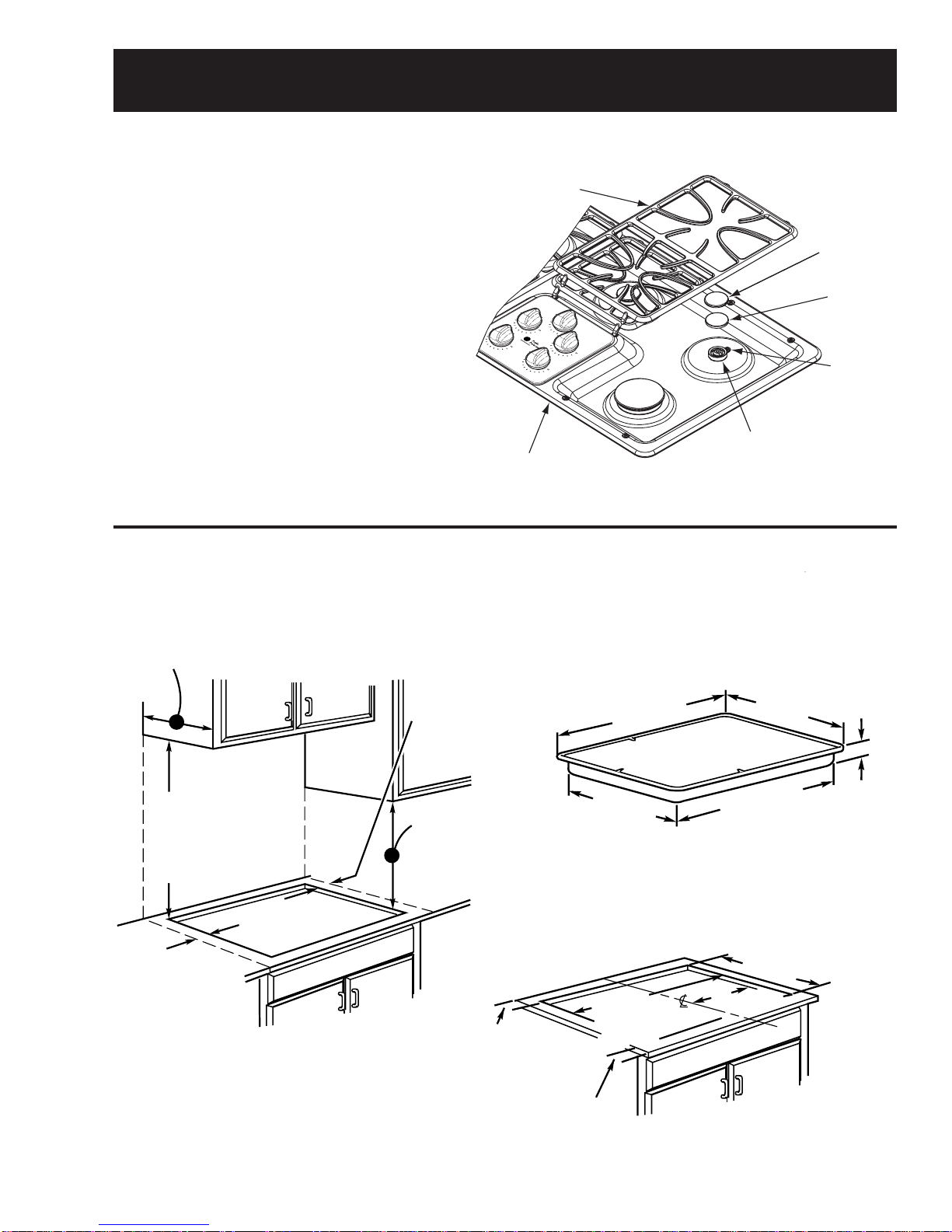
Wall coverings, countertops, and cabinets should
be able to withstand 200°F heat generated by the
cooktop.
Avoid placing cabinets above the cooktop.
If cabinets are placed above the cooktop, use
cabinets no more than 13 in. deep and allow a
minimum clearance of 30 in. between the cooking
surface and the bottom(s) of unprotected
cabinet(s).
If a 30-in. clearance between cooking surface and
overhead combustible material or metal cabinets
can not be maintained, protect the underside of
cabinets above cooktop with insulating millboard
at least 1/4-in. or gypsum board at least 3/16-in.
thick, covered with 28-gauge sheet steel or 0.020
in. thick copper.
Clearance between the cooking surface and
protected cabinets must never be less than 24 in.
Exception: Installation of a listed microwave oven
or cooking appliance over the cooktop shall
conform to the installation instructions packed with
theappliance.
Vertical distance from the plane of the cooking
surface to the bottom of adjacent overhead
cabinets extending closer than 1 in. to the plane of
the cooktop sides must not be less than 18 in.
Adjacent cabinets should be at least 8 in. from the
side of the cooktop.
GEA00745
CABINET SIDES
90°
STREET EL 2" DIA. HOLE (20 7/8"
FROM FRONT OF
COUNTERTOP TO
HOLE CENTER)
5" TO CENTER
OF 2" DIA. HOLE
FROM COUNTERTOP

– 6 –
Conversion to LP (Propane) Gas
The pressure regulator and the burner orifices are
set for natural gas. To use LP (propane) gas, the
regulator and burner orifices must be converted.
The LP orifice spuds for the cooktop burners can
be located within the literature package shipped
with the unit.
If you convert to LP gas, keep instructions and
natural gas orifices to convert back for use with
natural gas.
WARNING: If you are using LP (propane) gas, all
adjustments described in the following steps must
be made before attempting burner adjustments or
using cooktop.
WARNING: Use only approved pipe dope
resistant to LP gas.
Convert the Regulator
1. Disconnect the electrical power to the cooktop
and shut off the gas supply.
Note: The cooktop is shipped with a convertible
regulator and a set of LP orifices.
GEA00746
NAT.
POSITION
L.P./PROPANE
POSITION
CAP
SPRING
RETAINER
DOWN
FOR OFF
NAT
LP
LP
NAT
GASKET
PRESSURE REGULATOR
LP
NAT
NAT
LP
2. Unscrew the spring retainer cap from the
regulatorbody.
3. Press your thumb against the flat side of the
spring retainer and press down to remove the
retainer from the center of the cap.
4. Turn plastic spring retainer upside down so that
LP is showing at the bottom (see illustration
above) and reinstall spring retainer in the spring
retainercap.
5. Assemble the cap on the pressure regulator.
Install the LP Orifices
1. Remove the top grates, burner caps, burner
head, and spark igniter from the burner base.
GEA00747
ORIFICE SPUD
LOCATED THRU
THIS OPENING
REMOVE
THIS
ASSEMBLY
2. Remove 2 screws from the burner base using
a No. 15 torx head driver bit.
Note: The orifices have a spring-loaded retaining
ring around the hex head to hold the orifice in the
nut driver during installation and removal. A slight
amount of force is required to push the nut driver
down over the ring.
GEA00748
RETAINER
RING
3. Using a 7-mm or 9/32-in. nut driver, remove the
natural gas orifice from each burner and save.
These may be accessed through the hole in the
maintop.
Note: Use the Burner/Orifice specification chart
to determine location of proper orifices.
4. Locate the LP orifice spuds within the literature
package shipped with the unit. They will have a
digit number and an “L” on one side and an
engraved mark (I, II, III, or X) located on the top.
GEA00749
I II III X
These marks denote the precise location of
each orifice to the cooktop burner.
5. Install the LP orifices in their precise locations.

– 7 –
4-Burner Cooktop Models
6. Return the natural gas orifices to the plastic
bag along with these instructions for future
conversion back to natural gas.
Caution: When attaching the burner base to
glasstop unit, tighten to 10 in./lbs max torque.
Overtightening will cause damage.
7. Replace the burner bases, spark igniters,
heads, caps, and top grates.
4-Burner Cooktop Models
with 9,100 BTU/HR Burner on Right Front
(See rating plate on bottom of appliance)
5-Burner Cooktop Models
with 15,000 BTU/HR Burner on Right Front
(See rating plate on bottom of appliance)
GEA00750
BURNER
RR 6,000 .79 Lmm
LR 9,100 .90 Lmm
LF 8,100 .84 Lmm
RF 13,000 1.04 Lmm
BURNER OUTPUT RATING:BTU/HR
LP (PROPANE) GAS 10" W.C.P.
BTU RATE ORIF. SIZE
RR 6,000 1.18 Nmm
LR 11,000 1.61 Nmm
LF 9,100 1.50 Nmm
RF 15,000 1.93 Nmm
BURNER OUTPUT RATING:BTU/HR
ORIF. SIZE
BTU RATE
BURNERNatural Gas 4"W.C.P.
GEA00751
III
II
I
X
GEA00752
RR 6,000 1.18 Nmm
LR 9,100 1.50 Nmm
LF 9,100 1.50 Nmm
RF 9,100 1.50 Nmm
BURNER
RR 6,000 .79 Lmm
LR 8,100 .84 Lmm
LF 8,100 .84 Lmm
RF 8,100 .84 Lmm
BURNER OUTPUT RATING:BTU/HR
LP (PROPANE) GAS 10" W.C.P.
BTU RATE ORIF. SIZE
BURNER OUTPUT RATING:BTU/HR
ORIF. SIZE
BTU RATE
BURNER
Natural Gas 4"W.C.P.
GEA00753
II
II
I
II
GEA00754
GEA00755
BURNER OUTPUT RATING: BTU/HR
Natural Gas 4" W.C.P.
BURNER BTU RATE ORIF. SIZE
RR 6,000 1.18 Nmm
CR 6,000 1.18 Nmm
LR 9,100 1.50 Nmm
LF 11,000 1.61 Nmm
RF 15,000 1.93 Nmm
BURNER OUTPUT RATING: BTU/HR
LP (Propane) Gas 10" W.C.P.
BURNER BTU RATE ORIF. SIZE
RR 6,000 .79 Nmm
CR 6,000 .79 Nmm
LR 8,100 .84 Nmm
LF 9,100 .90 Nmm
RF 13,000 1.04 Nmm

– 8 –
Adjusting Low Flame Setting
WARNING: The following adjustments must be
made before turning on the burner. Failure to do so
could result in serious injury. Be sure pressure
regulator has been converted.
The top burner valves have low flame/simmer
adjustment screws in the center of the control
shafts. A flashlight may be needed to locate the
screw. A small thin-blade screwdriver (approxi-
mately 3/32-in. blade width) is needed to access
the screw.
1. Light 2 other burners and set the knob to a
Medium to Hi setting.
2. Light the burner to be adjusted and turn the
knob to LOW.
GEA00757
3. Remove the knob and insert a screwdriver into
the valve shaft.
4. Turn the adjustment screw until the flame
reaches the desired size.
5. Perform a flame stability test.
Flame Adjustments
The burners do not have air shutters adjustments
and use nonadjustable orifices. If the flame lifts off
of the burner, or if you experience “Yellow Tip”
flames and/or soot in the flames, be sure to check
thefollowing:
1. Gas pressure: 4-in. W.C.P. (natural) and 10-in.
W.C.P.(LP).
2. Inspect orifice to be sure it is drilled in the
center and free of debris or burrs.
3. Be sure the correct size orifice is in the proper
location.
4. Make sure the cooktop was properly converted
if on LP.
5. If the cause of sooting can not be found in the
above checks, replace the orifice with one
having a smaller diameter opening.
Testing Flame Stability
1. Turn the knob from HI to LOW quickly. If the
LOW flame goes out, increase the flame size
and test again.
2. With the burner on the LOW setting, open and
close the cabinet door under the cooktop. If the
flame is extinguished by the air currents cre-
ated by the door movement, increase the flame
height and test again.
Flame Recheck
After the adjustment is made, turn all burners off.
Ignite each burner individually. Observe the flame
at the HI position. Rotate the valve to the LOW
position and be sure the flame size decreases as
the valve is rotated counterclockwise.
Note: Once the conversion is complete and
checked OK, fill out the LP sticker and include
your name, organization, and date conversion was
made. Apply the sticker near the cooktop gas inlet
opening to alert others in the future that this
appliance has been converted to LP. If converting
back to natural gas from LP, please remove the
sticker so others know the appliance is set to use
natural gas.

– 9 –
Specifications and Nomenclature
Model Number
Serial Number
The first two numbers of the serial number
identify the month and year of manufacture.
Example: AZ123456S = January, 2000
A - JAN 2005 - H
D - FEB 2004 - G
F - MAR 2003 - F
G - APR 2002 - D
H - MAY 2001 - A
L - JUN 2000 - Z
M - JUL 1999 - V
R - AUG 1998 - T
S - SEP 1997 - S
T - OCT 1996 - R
V - NOV 1995 - M
Z - DEC 1994 - L
Note: The technical sheet is located under the
control panel.
The letter designating the
year repeats every 12
years.
Example:
T - 1974
T - 1986
T - 1998
J G P 9 6 3 B E C
Product
J = GE Cooking Product
Features
G = Gas
Configuration
P = Cooktop Feature Pack
Designates features–the higher
the number, the more features.
Grate Type
C = Continuous
Ignition System (Gas Models)
E = Electronic Pilotless Ignition
Glass Color
B = Black Glass
The serial plate of your cooktop is located
on the bottom of the burner box. In addition
to the model and serial numbers, it tells you
the ratings of the burners and the type of fuel
and pressure the cooktop was adjusted for
when it left the factory.
For burner BTU rate and orifice size, refer to the Conversion to LP (Propane) Gas chapter.
GEA00758


– 11 –
Cooktop Features and Controls
Throughout this manual, features and appearances may vary from the customer’s model.
Feature Index
1. Spill-proof Burners (2 or 3)
2. Simmer Spill-proof Burner
3. High-Power Spill-proof Burner*
4. Surface Unit Controls
5. Glass Cooktop Surface*
6. Cast-Iron Burner Grates*
*Some models
The new gas cooktop revitalization encompasses over 20 models of gas cooktops. It includes 30-in.,
4-burner and 36-in., 5-burner models in both deepdish metal and glass cooktop configurations. All gas
cooktop revitalization models have spill-proof burners and electric ignition systems.
36-in. Glasstop Cooktop
36-in. Deepdish Cooktop
30-in. Glasstop Cooktop 30-in. Deepdish Cooktop

– 12 –
Ignition System
The surface burners are lighted by electric
ignition,eliminating the need for standing pilot
lights with constantly burning flames.
The ignition system consists of 4 (or 5) spark
switches (1 on each valve), 4 (or 5) spark
electrodes (1 on each burner), and a spark
module.
The burner control knob must be turned to the
LITE position to light the burner and out of the
LITE position to stop the sparking after the
burner has ignited.
All 4 electrodes will spark when any burner
control knob is in the LITE position.
Lighting a Burner
Push the control knob in and turn it
counterclockwise to the LITE position.
GEA0026
1
Check to be sure the burner you
turned on is the one you want to use
.
After the burner ignites, turn the knob to adjust the
flame to the desired size. To turn a burner off, turn
the knob clockwise as far as it will go, to the OFF
position.
In case of a power failure, you can light the burn-
ers with a match. Hold a lit match to the burner,
then push in and turn the control knob to the LITE
position. Use extreme caution when lighting burn-
ers this way. Burners in use when an electrical
power failure occurs will continue to operate
normally.
Built-In Gas Cooktops
GEA00763
JGP963SEC JGP933SEC JGP636WEV JGP336WEV
JGP963WEC JGP962SEC JGP933WEC JGP932SEC JGP636CEV JGP336CEV JGP628WEC JGP328WEC
JGP963CEC JGP962TEC JGP933CEC JGP932TEC JGP636AEV JGP336AEV JGP628CEC JGP328CEC
JGP963BEC JGP962BEC JGP933BEC JGP932BEC JGP636BEV JGP336BEV JGP628BEC JGP328BEC JGP320EV
Features
222
Stainless Stainless Glass Glass Enameled Enameled Enameled
Continuous Continuous Continuous Continuous Continuous Continuous Chrome
Stainless Stainless White White
White Stainless White Stainless Bisque Bisque White
Bisque White Bisque White Almond Almond Bisque Bisque
Black Black Black Black Black Black Black Black White/Black
Controls Upfront Upfront Upfront Upfront
Appearance
SS SS WW WW
WW SS WW SS AA AA WW WW
CC WW CC WW BB BB CC CC
BB BB BB BB CC CC BB BB WH/BL
36 36 30 30 36 30 36 30 30
54 59 44 49 38 30 51 44 31
Power/Ratings
Burners
GE
4 Standard4 Sealed
4 Sealed
4 Sealed
Tempered Porcelain Porcelain Porcelain
Standard Steel
Porc.-Enam.Porc.-Enam.
Porc.-Enam.
Deluxe Cast
Right Side Right Side Right Side
(3) 9.1/8.1
(1) 6.0/6.0 (3) 9.1/8.1
(1) 6.0/6.0 (4) 9.1/8.0
(1) 12.0/9.4
(2) 9.5/7.0
(1) 5.0/4.0
(2) 5.0/4.0
(2) 9.5/7.0
(1) 12.0/9.4
(1) 15.0/14.0
(1) 11.0/10.0
(1) 9.1/8.1
(2) 6.0/6.0
(2) 6.0/6.0
(1) 9.1/8.1
(1) 11.0/10.0
(1) 15.0/14.0
(1) 15.0/14.0
(1) 11.0/10.0
(1) 9.1/8.1
(2) 6.0/6.0
Porc.-Enam.
Deluxe Cast
Tempered
Ceramic Glass
Deluxe Cast
Right SideRight Side
Deluxe Cast
PorcelainCeramic Glass
Deluxe Cast
GE Profile™
GE Profile Performance Series™
5 Sealed
4 Sealed
4 Sealed
5 Sealed
5 Sealed
Porcelain
Deluxe Cast
(1) 15.0/14.0
(1) 11.0/10.0
(1) 9.1/8.1
(2) 6.0/6.0
*SS = Stainless Steel, WW = White on white, CC = Bisque, AA = Almond on almond, BB= Black on black, WH = White, BL = Black.
†A set of LP orifices is included with each cooktop for LP conversion. Factory set for Natural Gas.
(000’s/BTU’s): Nat. Gas/
LP Gas†
Gas cooktop electrical rating
Approx. shipping weight (lbs.)
Cooktop width (in inches)
Weight & Dimensions
Color appearance*
Control panel
One-piece drip pans
Cooktop grates
Cooktop surface
Electronic pilotless ignition
Precise Simmer burner(s)
Maximum Output burner
Max. Plus Burner 15,000 BTU
Cooktop burners
120V, 60Hz, 5A
White


– 15 –
Table of Contents
Igniter Removal .......................................................................................................16
Burner and Top Removal........................................................................................16
Burner Bracket Removal ........................................................................................17
Spark Module Removal...........................................................................................17
Igniter Switch Removal ..........................................................................................18
Valve Removal .........................................................................................................18
36-in. Models .......................................................................................................18
30-in. Models .......................................................................................................18
Manifold Removal....................................................................................................19
36-in. Models .......................................................................................................19
30-in. Models .......................................................................................................19
Brace Removal ........................................................................................................20
Mechanical Disassembly

– 16 –
3. Unplug the wire from the base of the igniter.
Burner and Top Removal
Note: The cooktop does not need to be removed
from the countertop.
1. Remove all igniters (see Igniter Removal).
GEA00771
Torx
Screw Igniter
Graphite
Gasket
2. Remove 2 Torx (T15) screws from each
burner base and remove the burner bases.
Caution: When replacing burner bases on
glasstop models, do not overtighten screws.
Caution: Graphite gaskets are very fragile. Care
must be given to avoid breaking.
3. Remove the flat graphite gaskets and set
aside.
4. Remove the knobs from the cooktop.
5. Lift off the cooktop and place it on a flat,
protected surface.
6. Remove the graphite gaskets (glass cooktop
models only) and set aside.
Note: When reassembling the glass cooktop
models, replace the top before replacing the
graphite gaskets to avoid damage to the gaskets.
Caution: There is a foam gasket (seal) between
the cooktop and the burner box (nonglass models
only). This gasket must stay in place to ensure
proper air flow to the burners (see Igniter Re-
movalillustration).
Note: The cooktop itself is not equipped with a gas
shutoff valve. If installed correctly, a shutoff valve
will be in the main gas supply line “downstream” of
the appliance pressure regulator.
Igniter Removal
1. Remove the burner grate, burner cap, and
burner head from the cooktop.
GEA00741
BURNER
GRATE
BURNER
CAP
BURNER
HEAD
SPARK
IGNITER
BURNER BOX
BOTTOM
BURNER
BASE
2. Insert a small, flat screwdriver blade between
the edge of the igniter and burner base and lift
theigniter.
Caution: When removing the wire from the igniter,
make sure you do not damage the heat shrink
insulation on the wire. If damaged, repair the wire
insulation with fiberglass tape.
GEA00769
Burner
Base
Burner
Base
Graphite
Gasket
Graphite
Gasket
Glasstop ModelGlasstop Model
Burner
Head
Burner
Head
Burner
Cap
Burner
Cap
GEA00770
Burner
Head
Burner
Head
Burner
Base
Burner
Base
Deepdish ModelDeepdish Model
Graphite
Gasket
Graphite
Gasket
Burner CapBurner Cap

– 17 –
Burner Bracket Removal
1. Remove the burners and top (see Burner and
Top Removal).
2. Remove the insulation blanket.
GEA00773
Graphite GasketGraphite GasketIgniter
Wire
Igniter
Wire
RetainerRetainer Burner Support
Burner Support
Burner Support
3. Remove the graphite gasket ring (glasstop
models only).
4. Compress the legs of the burner support and
lift up to remove.
GEA00774
1/4-in. Screw1/4-in. Screw
1/2-in. Nut1/2-in. Nut
5. Remove the 1/2-in. nut on the gas line to the
burner bracket.
6. Remove 2 screws (1/4-in.) and the igniter wire
from the burner bracket.
Note: When installing, be sure the igniter wire is
placed through the hole with the retainer clip.
Spark Module Removal
1. Remove insulation material if applicable.
2. Note positions and unplug the wires to the
spark module.
GEA00775
30-in. Model
30-in. Model
30-in. Model
Spark ModuleSpark Module
1/4-in. Screw1/4-in. Screw
3. Remove 2 screws (1/4-in.) and the mounting
bracket from the cooktop pan (30-in. models
only).
GEA00776
36-in. Model
36-in. Model
36-in. Model
Spark ModuleSpark Module
1/4-in. Screw1/4-in. Screw
4. Remove the 1/4-in. screw and the spark
module from the mounting bracket.

– 18 –
Igniter Switch Removal
1. Remove the burners and top (see Burner and
Top Removal).
2. Unplug the wires to the igniter switch.
GEA00777
Color
Indicator
Color
Indicator
Molded
Molded
Lock Fit
Molded
Lock Fit
Note: On 36-in. models, note the color and posi-
tion of switches.
3. Lift each igniter switch off the valve stem.
Note: When replacing the switch, replace the
entire harness with colors in same positions. The
bottom of the switch is molded to conform to the
top of the valve for a locked-in fit.
Valve Removal
36-in.Models
1. Remove the burners and top (see Burner and
Top Removal).
GEA00778
Igniter
Switch
Switch
Igniter
Switch
2. Lift the igniter switches off the valve stems.
(Note the color and positions of the switches.)
GEA00779
Straight
Straight
Manifold
Manifold
Straight
Manifold
5/8-in. Nut
5/8-in. Nut
5/8-in. Nut 1/2-in. Nut
1/2-in. Nut
1/2-in. Nut
3. Remove the 1/2-in. nut on the gas line to the
valve and remove the gas line.
4. Remove the 5/8-in. nut on the gas line to the
horseshoe-shaped manifold or the 9/16-in. nut
on the gas line to the straight manifold and
remove the gas line.
5. Remove the 1/4-in. screws and the manifold
from the burner box.
GEA00780
1/4-in. Screws
1/4-in. Screws
1/4-in. Screws
6. Remove the 1/4-in. screw from the manifold
and remove the valve.
Valve Removal
30-in.Models
1. Remove the burners and top (see Burner and
Top Removal).
Other manuals for JGP628
5
This manual suits for next models
5
Table of contents
Other GE Cooktop manuals
Popular Cooktop manuals by other brands

Siemens
Siemens EH70650 Repair instructions

Miele
Miele MasterChef KM342 installation instructions

Ariston
Ariston PH 750 RT GH AUS user manual

Blanco
Blanco CGG302FFC Use, installation and maintenance instructions

Viking
Viking F20528 Use & care manual

Thermador
Thermador STEEL GAS STAR SGSX304 Installation instructions manual

Viking
Viking DGCU105-4B Specifications

WilTec
WilTec 61233 Operation manual

Jenn-Air
Jenn-Air 30" (76.2 cm) Cooktop installation instructions

KitchenAid
KitchenAid KGCC566RBL03 installation instructions

Kenyon
Kenyon Lite Touch Horizon B42501 Installation guide & operation manual

Gaggenau
Gaggenau CV 282 instruction manual