Installation
Instructions
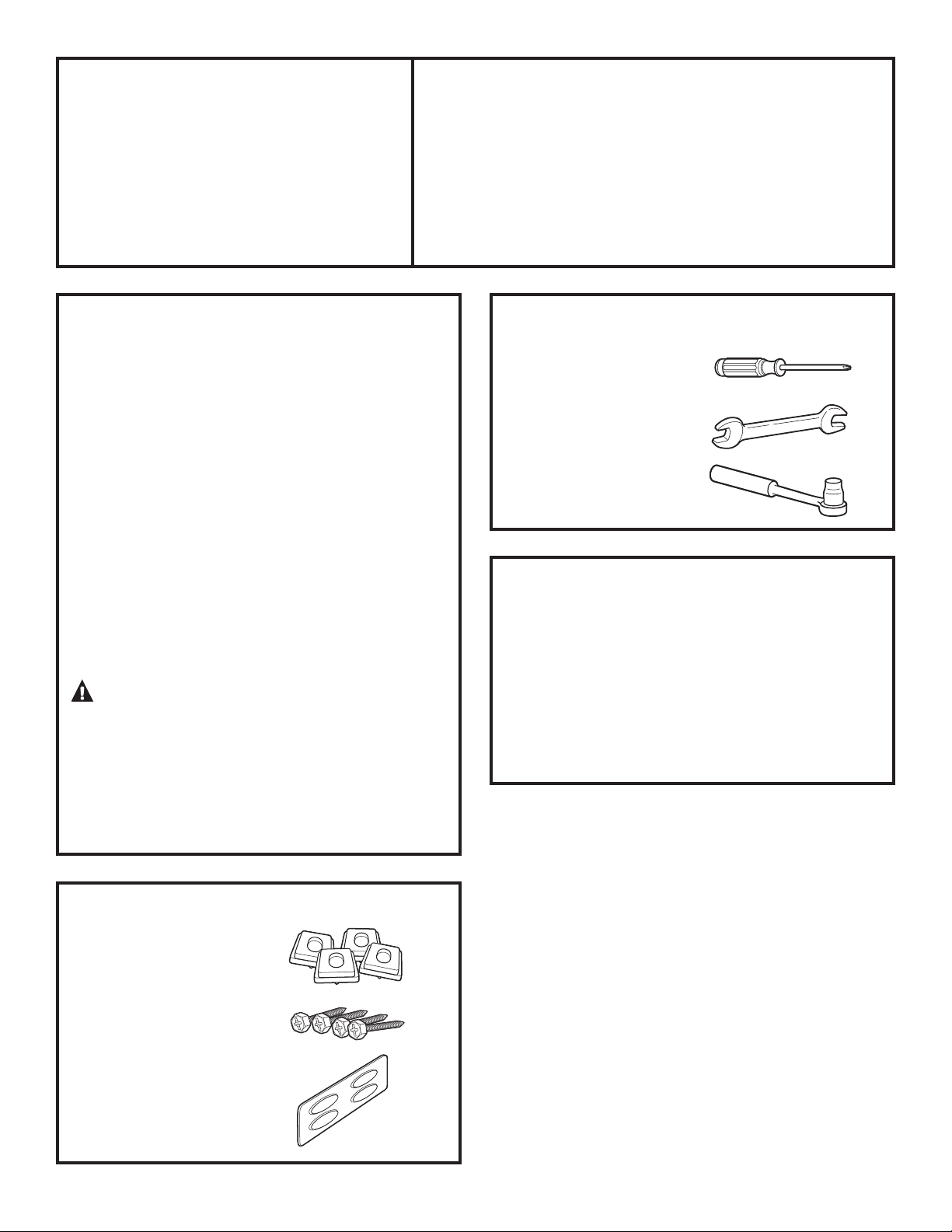
KIT CONTENTS
4 Support Pads
4 Mounting Screws
Drawer Divider
1
SBSD137, SBSD227
TOOLS YOU WILL NEED
Phillips Head
Screwdriver
9/16” Open End Wrench
or Adjustable Wrench
8 mm Socket Wrench
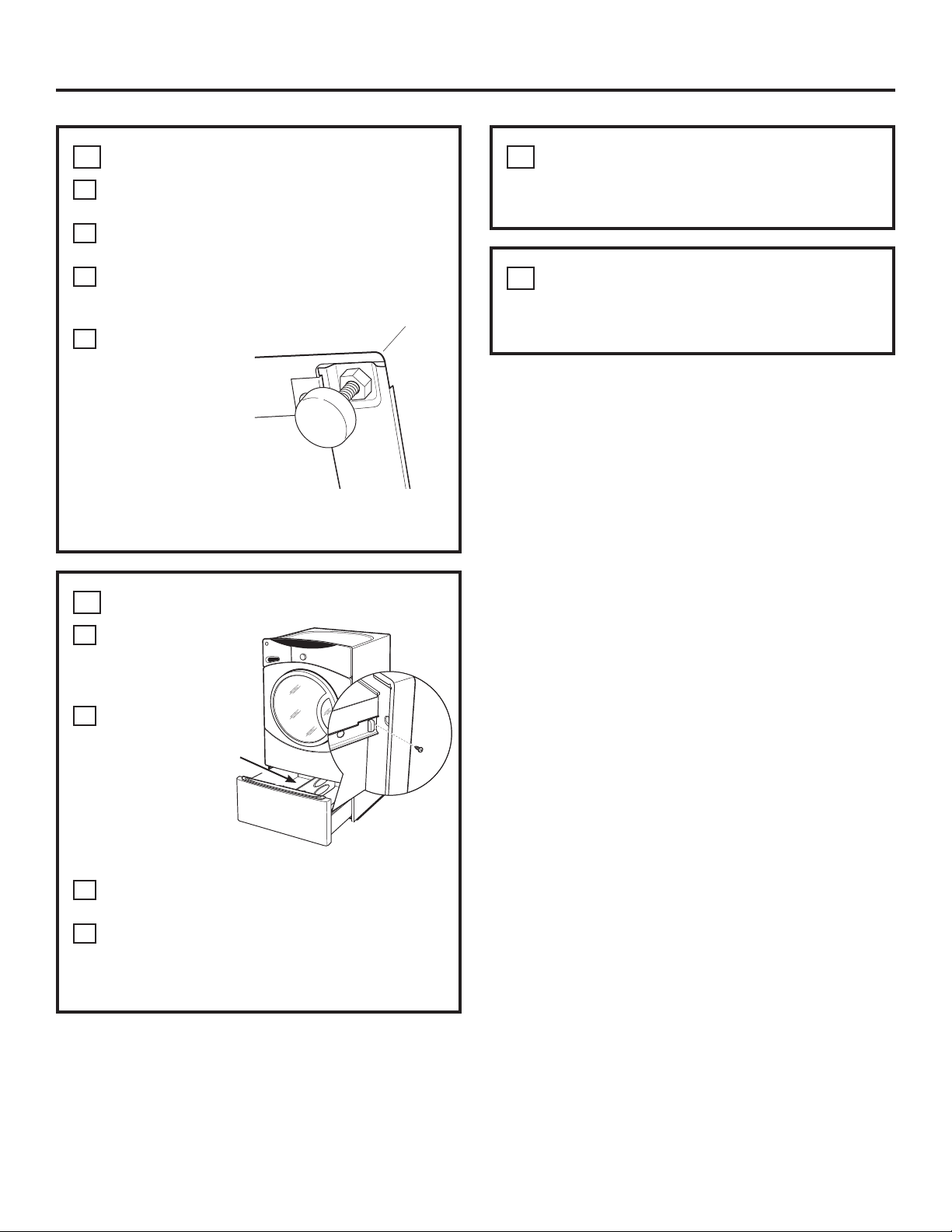
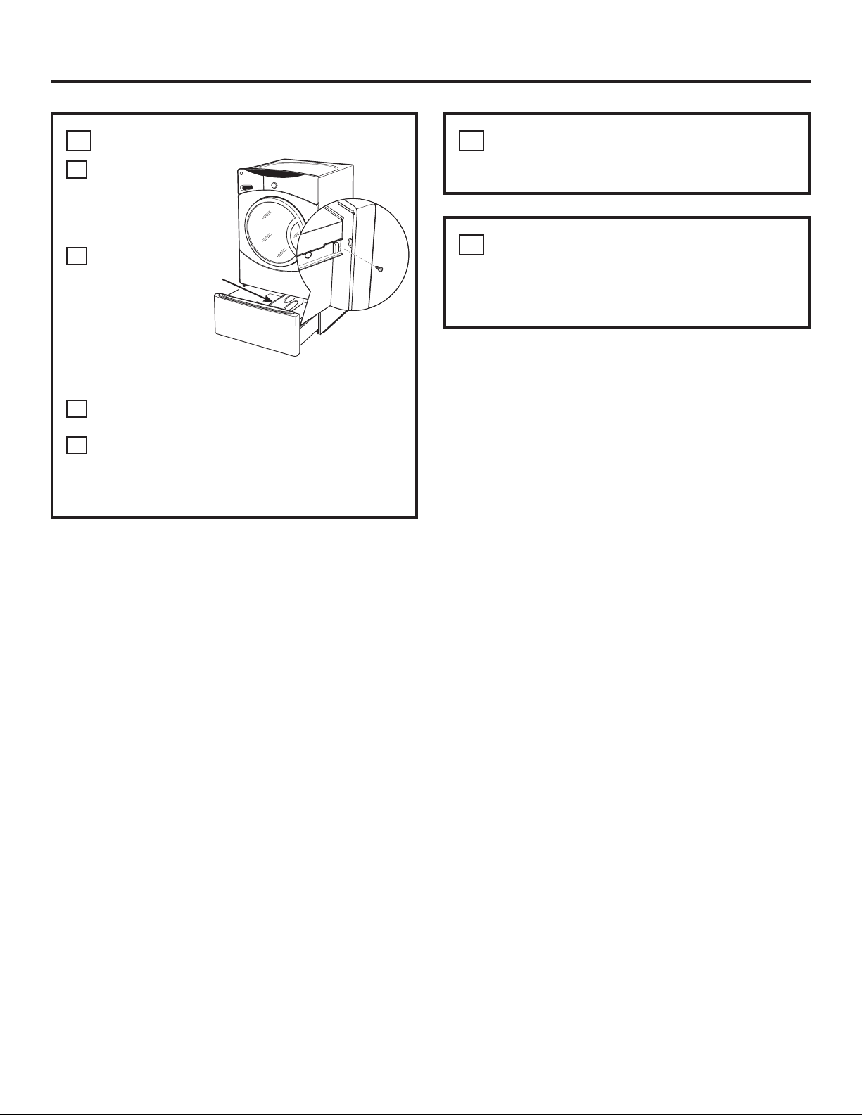
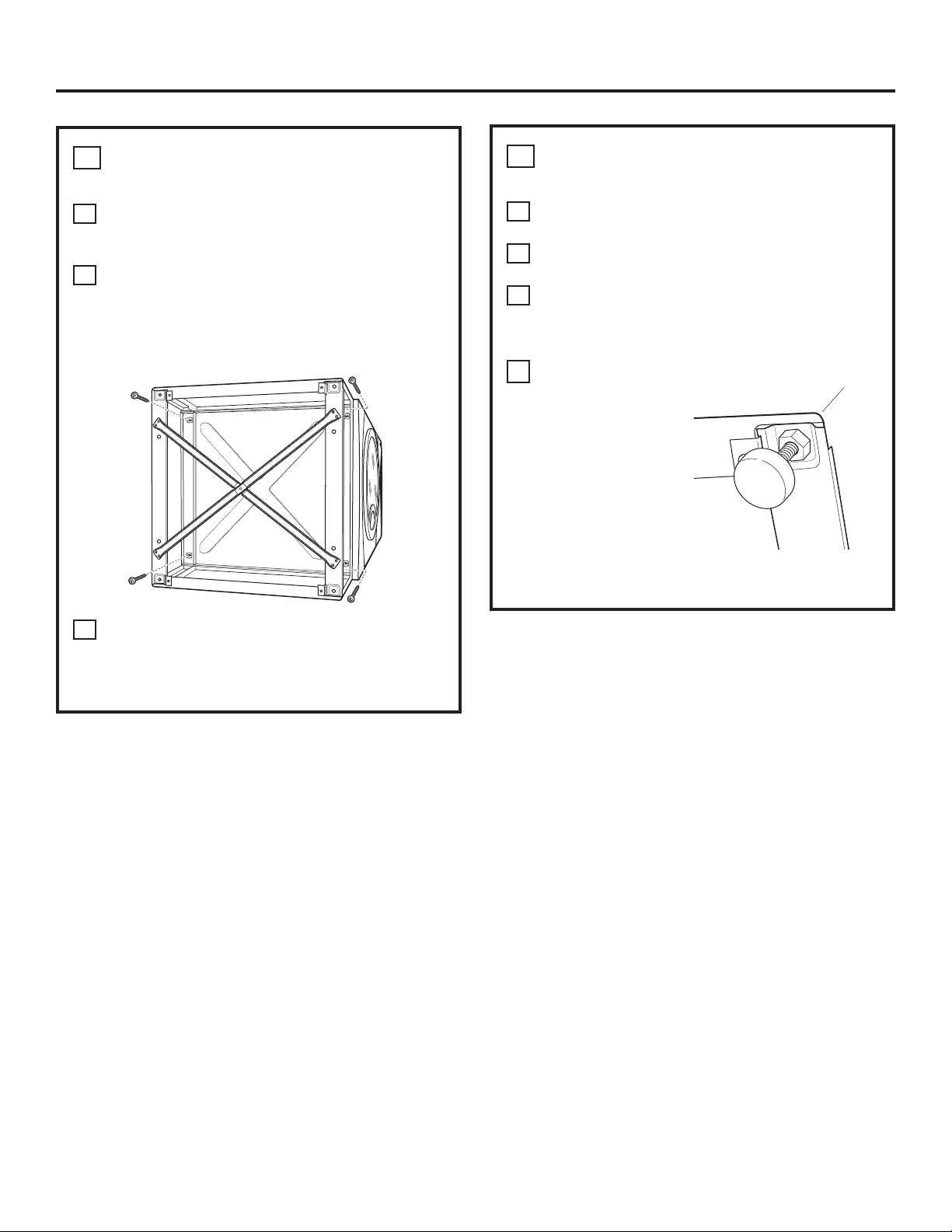
1REMOVE THE LEVELING LEGS
ACarefully lay the washer or dryer on its side to
access the leveling legs on the bottom of the
appliance.
IMPORTANT: Do not lay the washer or dryer on
its back! Do not remove the shipping bolts on the
back side of the washer. The bolts must remain in
place until the washer is returned to an upright
position.
BUse an open-end wrench to remove the
washer or dryer leveling legs.
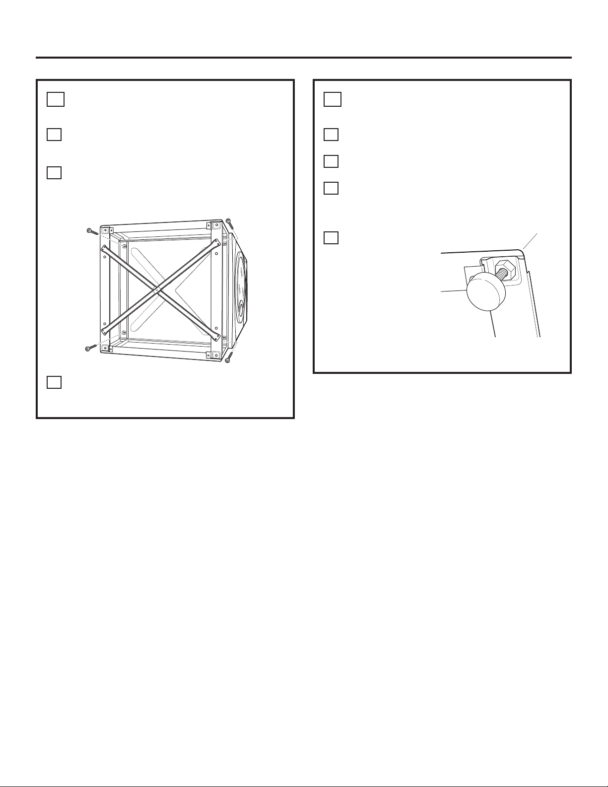
INSTALLATION PREPARATION
Remove the packaging.
The Drawer divider is taped at the top of the
shipping carton. Remove the divider and set aside
for final installation.
Flatten the product carton to use as a pad
to lay the washer or dryer down on its side.
Continue using the carton to protect the finished floor
in front of the installation location.
Back out and remove
all 4 leveling legs
Instructionsenfrançais: ................ 4
Instrucciones en español: ............... 8
For Washer Models: GBVH5140, GBVH6260, GCVH6260, GCVH6600, GCVH6800, GFAN1000,
GFAN1100,
GFWH1200, GFWH1300, GFWH1400, GFWH1405, GFWH2400,
GFWH2405, GFWN1000, GFWN1100, GFWN1200, GFWN1300, GFWS1500,
GFWS1505, GFWS3500, GFWS3505,
GHDVH626, GHDVH670,
GMAN1200,
WBVH5100,
WBVH6240,
WCVH5300,
WCVH6260, WCVH6600,
WCVH6800,
WHDVH626 & WHDVH660
For Dryer Models: DBVH510, DBVH512, DCVH515, DCVH660, DHDVH52, DHDVH66,
GFDM245, GFDN100, GFDN110, GFDN120, GFDN130, GFDN240, GFDN245,
GFDS140, GFDS145, GFDS150, GFDS155, GFDS350, GFDS355, GFMN100,
GFMN110, GFMN240, GFMS350, GFMS355, GMMN120,
PBVH415, PCVH565,
PCVH680,
PDVH515, PHDVH52 & PHDVH57
BEFORE YOU BEGIN
Read these instructions completely
and carefully.
•IMPORTANT ³6DYHWKHVHLQVWUXFWLRQV
for local inspector’s use.
•IMPORTANT ³2EVHUYHDOOJRYHUQLQJ
codes and ordinances.
• Note to Consumer – Keep these instructions with
your Owner’s Manual
for future reference.
• Completion time – 1 to 2 hours
• Proper installation is the responsibility
of the installer.
• Product failure due to improper installation is not
covered under the Warranty.
CAUTION ³'XHWRWKHVL]HDQGZHLJKW
of these products, and to reduce the risk of
personal injury or damage to the product,
TWO PEOPLE ARE REQUIRED
FOR PROPER INSTALLATION.
• See washer and dryer installation instructions
for additional installation requirements and
guidelines.
49-90321-2 175D1807P589 11-13 GE


 installation instructions")