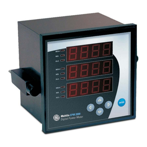
GE EPM 5100 User manual

GE Consumer & Industrial
Multilin
EPM 5100
Electronic Power Meter
INSTRUCTION MANUAL
Manual P/N: 1601-0164-A2
Manual Order Code: GEK-113391A
Copyright © 2008 GE Multilin
GE Multilin
215 Anderson Avenue, Markham, Ontario
Canada L6E 1B3
Tel: (905) 294-6222 Fax: (905) 201-2098
Internet: http://www.GEindustrial.com/multilin
1601-0164-A2
ISO9001:2000
G
E
M
U
L
T
I
L
I
N
R
E
G
I
S
T
E
R
E
D
GE Multilin's Quality Management
System is registered to ISO9001:2000
QMI # 005094
UL # A3775
Courtesy of NationalSwitchgear.com

CHAPTER 4:
EPM 5100 ELECTRONIC POWER METER – USER GUIDE 4–1
Table of Contents
1: OVERVIEW PRODUCT DESCRIPTION ............................................................................................................... 1-1
FEATURES ............................................................................................................................................ 1-3
METERED FUNCTIONS ......................................................................................................... 1-3
POWER MANAGEMENT FEATURES .................................................................................... 1-4
PHYSICAL DESCRIPTION ............................................................................................................... 1-6
FRONT PANEL ...................................................................................................................... 1-6
DISPLAY ................................................................................................................................ 1-6
BACK PANEL ......................................................................................................................... 1-6
PANEL MOUNTING .............................................................................................................. 1-7
DIMENSIONS, CASE TYPE UNIT ......................................................................................... 1-8
DIMENSIONS, PANEL MOUNTING UNIT ............................................................................ 1-9
ORDERING ........................................................................................................................................... 1-11
ORDER CODES ..................................................................................................................... 1-11
ACCESSORIES ....................................................................................................................... 1-11
APPLICATIONS ................................................................................................................................... 1-12
TYPICAL APPLICATIONS ....................................................................................................... 1-12
PT AND CT INPUTS ............................................................................................................. 1-12
SPECIFICATIONS ............................................................................................................................... 1-13
INPUTS .................................................................................................................................. 1-13
INTERCONNECTIONS ............................................................................................................ 1-13
ENVIRONMENTAL ................................................................................................................. 1-13
2: INSTALLATION OVERVIEW ........................................................................................................................................... 2-1
INSTALLATION PROCESS ..................................................................................................... 2-1
MECHANICAL INSTALLATION ..................................................................................................... 2-3
PANEL MOUNTING FOR NEW INSTALLATION .................................................................. 2-3
RETROFIT INSTALLATION ..................................................................................................... 2-4
ELECTRICAL INSTALLATION ......................................................................................................... 2-10
INSTRUMENT TRANSFORMER CONNECTIONS ................................................................... 2-10
PULSE INITIATION CONNECTIONS ..................................................................................... 2-13
COMMUNICATIONS INSTALLATION ......................................................................................... 2-15
MODBUS CONNECTIONS .................................................................................................... 2-15
INSTALLATION OF THE COMMUNICATIONS CARD ........................................................... 2-15
3: METERING METER OPERATIONS ....................................................................................................................... 3-1
METER SELF-TEST ............................................................................................................... 3-1
INTEGRITY OF METERED VALUES ....................................................................................... 3-1
COMMUNICATIONS ERROR ................................................................................................. 3-2
DISPLAY OF METERED VALUES .......................................................................................... 3-2
KEYPAD FUNCTIONS ............................................................................................................ 3-2
METERING ACCURACIES ..................................................................................................... 3-3
WYE CONFIGURATION METERING FUNCTIONS ................................................................. 3-4
DESCRIPTION ........................................................................................................................ 3-4
CURRENT (RMS) .................................................................................................................... 3-4
VOLTAGE ...............................................................................................................................3-4
POWER .................................................................................................................................. 3-4
Courtesy of NationalSwitchgear.com

4–2 EPM 5100 ELECTRONIC POWER METER – USER GUIDE
CHAPTER 4:
APPARENT POWER .............................................................................................................. 3-5
ENERGY ................................................................................................................................. 3-5
FREQUENCY .......................................................................................................................... 3-5
DEMAND ...............................................................................................................................3-5
POWER FACTOR ................................................................................................................... 3-6
MISCELLANEOUS FUNCTIONS ............................................................................................ 3-6
TRANSFORMER RATIOS ....................................................................................................... 3-6
DELTA CONFIGURATION METERING FUNCTIONS ..............................................................3-7
DESCRIPTION ........................................................................................................................ 3-7
CURRENT (RMS) .................................................................................................................... 3-7
LINE-TO-LINE VOLTAGE (RMS) ........................................................................................... 3-7
POWER .................................................................................................................................. 3-7
ENERGY ................................................................................................................................. 3-8
FREQUENCY .......................................................................................................................... 3-8
DEMAND ...............................................................................................................................3-8
POWER FACTOR ................................................................................................................... 3-8
MISCELLANEOUS FUNCTIONS ............................................................................................ 3-9
TRANSFORMER RATIOS ....................................................................................................... 3-9
4: PROGRAMMING PROGRAM MODE .............................................................................................................................. 4-1
INTRODUCTION ..................................................................................................................... 4-1
ACCESS TO PROGRAM FUNCTIONS .........................................................................................4-2
OVERVIEW ............................................................................................................................ 4-2
RESTRICTED ACCESS ........................................................................................................... 4-3
EXITING PROGRAM MODE .................................................................................................. 4-4
DATA RESETTING .............................................................................................................................. 4-5
DESCRIPTION ........................................................................................................................ 4-5
DEMAND RESET ................................................................................................................... 4-5
ENERGY RESET ..................................................................................................................... 4-5
METER INITIALIZE ................................................................................................................. 4-6
ERRORS CLEAR ..................................................................................................................... 4-6
DATA FORMATTING ......................................................................................................................... 4-7
OVERVIEW ............................................................................................................................ 4-7
NORMAL SCROLL ................................................................................................................. 4-7
ENERGY FORMAT ................................................................................................................. 4-9
DEMAND FORMAT ............................................................................................................... 4-9
VOLTAGE FORMAT ............................................................................................................... 4-10
CURRENT FORMAT ............................................................................................................... 4-10
LEADING ZEROS ................................................................................................................... 4-10
SCROLL TIME ........................................................................................................................ 4-10
COMMUNICATIONS VALUES ....................................................................................................... 4-12
COMMUNICATION ADDRESS SETUP .................................................................................. 4-12
BAUD RATE SETUP .............................................................................................................. 4-12
EPM COMPATIBILITY SETUP .............................................................................................. 4-13
PULSE OUTPUTS ............................................................................................................................... 4-14
PULSE OUTPUT SETUP ........................................................................................................ 4-14
UPGRADING FROM ELECTROMECHANICAL METERS ........................................................ 4-14
UPGRADE CALCULATION EXAMPLE ................................................................................... 4-15
CONFIGURATION .............................................................................................................................. 4-16
OPTIONS ...............................................................................................................................4-16
PT RATIO .............................................................................................................................. 4-16
CT RATIO .............................................................................................................................. 4-16
DEMAND PERIOD SETUP .................................................................................................... 4-17
Courtesy of NationalSwitchgear.com
CHAPTER 4:
EPM 5100 ELECTRONIC POWER METER – USER GUIDE 4–3
METER TYPE ......................................................................................................................... 4-17
RESTRICTED ACCESS FUNCTIONS ............................................................................................ 4-18
ACCESS RESTRICT ................................................................................................................ 4-18
NEW PASSWORD ................................................................................................................. 4-18
DEFAULT SETTINGS ......................................................................................................................... 4-19
DESCRIPTION ........................................................................................................................ 4-19
5: COMMUNICATIONS INTRODUCTION ................................................................................................................................ 5-1
OVERVIEW ............................................................................................................................ 5-1
EVENTS .................................................................................................................................. 5-1
MODBUS REGISTER MAPS .................................................................................................. 5-2
MODBUS FORMAT CODES .................................................................................................. 5-5
6: MISCELLANEOUS TROUBLESHOOTING ....................................................................................................................... 6-1
TROUBLESHOOTING GUIDE ................................................................................................ 6-1
REVISION HISTORY .......................................................................................................................... 6-4
RELEASE DATES ................................................................................................................... 6-4
WARRANTY ......................................................................................................................................... 6-5
GE MULTILIN WARRANTY .................................................................................................. 6-5
Courtesy of NationalSwitchgear.com
EPM 5100 ELECTRONIC POWER METER – USER GUIDE 1–1
EPM 5100 Electronic Power Meter
Chapter 1: Overview
GE Consumer & Industrial
Multilin
Over view
1.1 Product Description
The GE Multilin EPM 5100 Electronic Power Meter is a full-function electronic meter with
optional pulse initiation and communications features. The communications option
supports the ‘open-architecture’ Modbus protocol and can be easily installed in the field at
a later date. The EPM 5100 is available with the following mounting options:
• An industry-standard SI-compatible case to maintain drawout capability, allowing
for easy upgrade or retrofit from existing DS-63, DS-64, or DS-65
electromechanical watthour meters (case type unit).
• A light compact plastic enclosure for panel mounting (panel mount unit).
The EPM 5100 continuously monitors specified line characteristics and displays the desired
functions and calculated values on a two-line, alphanumeric liquid crystal display (LCD) on
the front panel. The meter samples each of the current and voltage inputs 480 times per
second, and the display is updated every three seconds.
Courtesy of NationalSwitchgear.com

1–2 EPM 5100 ELECTRONIC POWER METER – USER GUIDE
CHAPTER 1: OVERVIEW
FIGURE 1–1: EPM 5100 Meter
Metered and calculated values appear
on the two-line liquid crystal display. The
value appears first, followed by the
paramter name. The parameters appear
in the order listed on the inside of
the door.
Press the SELECT ENTER key to switch
between normal and alternate scroll in
Metering mode or to select functions and
options in Program mode.
Press the SCROLL keys to scroll through
the metered functions in the Metering mode
or through the menus of functions and
options in the Program mode.
Open the door at the bottom of the front
cover to adjust the display contrast or to
view the list of measured parameters.
Courtesy of NationalSwitchgear.com
CHAPTER 1: OVERVIEW
EPM 5100 ELECTRONIC POWER METER – USER GUIDE 1–3
1.2 Features
1.2.1 Metered Functions
The electrical parameters and status information monitored and displayed by the EPM
5100 are shown in the following table. Note that the displayed parameters are dependent
on whether the meter is configured as Wye or Delta.
Table 1–1: EPM 5100 Metered Functions
Normal Scroll, Wye Normal Scroll, Delta
Current (rms) phase A, B, C, and neutral Current, phase A, B, and C
Voltage (rms) phase A-N, B-N, and C-N Voltage (rms) phase A-B, B-C, and C-A
Voltage (rms) phase A-B, B-C, and C-A Watts, phase A-B, B-C, and total
Watts, phase A, B, C, and total Watts, demand and peak demand
Watts, demand and peak demand Vars, phase A-B, B-C, and total
Vars, phase A, B, C, and total VA, phase A-B, B-C, and total
VA, phase A, B, C, and total Power Factor, Total
Power factor, total Watthours, Total
Watthours, total Varhours, total lag (+) and total lead (–)
Varhours, total lag (+) and total lead (–) VAhours, Total
VAhours, total Frequency, in hertz
Frequency, in hertz
Courtesy of NationalSwitchgear.com
1–4 EPM 5100 ELECTRONIC POWER METER – USER GUIDE
CHAPTER 1: OVERVIEW
1.2.2 Power Management Features
The EPM 5100 is available with the Power Leader communications options cards (catalog
number PLA3CMAG01 for Modbus RTU). The Modbus option provides the following
additional features:
• Remote viewing of all metered functions and configuration data at the host
computer.
• Graphical trending of most metered functions.
• User-defined remote alarms.
• Extensive reporting capabilities, including dynamic data exchange (DDE) for
exporting data for analysis by external software.
Table 1–2: EPM 5100 Metered Functions (ctd.)
Alternate Scroll, Wye Alternate Scroll, Delta
Current, phase A, B, and C demand Current, phase A and C demand
Current, phase A, B, and C peak Current, phase A and C peak
Watts demand at peak VA Watts demand at peak VA
Vars, demand lag (+) and lead (–) Vars, demand lag (+) and lead (–)
Vars, peak demand lag (+) and lead (–) Vars, peak demand lag (+) and lead (–)
VA, demand and peak demand VA, demand and peak demand
Q-hours, total Q-hours, Total
Power factor, phase A, B, C, and
average Power factor, phase A-B, B-C, and avg.
Power factor, demand Power factor, demand
Power factor, at peak VA Power factor, at peak VA
Number of demand resets Number of demand resets
Time left in demand Time left in demand
Number of power outages Number of power outages
Potential Transformer Ratio Potential Transformer Ratio
Current Transformer Ratio Current Transformer Ratio
Courtesy of NationalSwitchgear.com
CHAPTER 1: OVERVIEW
EPM 5100 ELECTRONIC POWER METER – USER GUIDE 1–5
The following figure contains an example of a Power Leader power management system
using the EPM 5100 and other Power Leader devices.
FIGURE 1–2: Example Power Leader System
HOST
EPM Power
Leader™ Meter Spectra RMS™
Extended Function
Modules
EPM Power Leader™
Monitor (remote)
Power Leader
Junction Box
8000 Line
Motor Control Center
Power Leader
Repeater
EPM Power
Leader™ Meter
EPM Power
Leader™ Meter
Power/VAC Medium
Voltage Switchgear
AKD-8 Low-Voltage
Switchgear
MDP
Overcurrent
Relays with
Comnet MicroVersaTrip PM™
Trip Units in
AKR Low-Voltage
Circuit Breakers Power Break
Low-Voltage Switchboard
EPM Power
Leader™ Monitor
MicroVersaTrip PM™
Trip Units in Power Break
Circuit Breakers
Courtesy of NationalSwitchgear.com
1–6 EPM 5100 ELECTRONIC POWER METER – USER GUIDE
CHAPTER 1: OVERVIEW
1.3 Physical Description
1.3.1 Front Panel
The front panel has a two-line, 16-character per line LCD and a three-button keypad for
view data and configuring the meter. The communication port and the voltage, current,
and pulse initiation terminals are located on the back of the meter.
The front panel contains the following features:
• A 3.8" by 0.9" two-line LCD that can display up to 16 characters per line.
• Three pushbuttons for scroll up, scroll down, and alternate scroll/enter. Operating
procedures for these buttons are described in Chapter 3.
• An additional secret button for accessing the Program mode. Operating
procedures for the Program mode are described in Chapter 4.
• A complete list of available metering and a display contrast-adjustment knob are
located under a flip-down door.
1.3.2 Display
Any of the metered functions can be viewed by pressing the SCROLL buttons or allowing the
EPM 5100 to automatically scroll through the parameters. All metered values are updated
every three seconds, whether or not they are being displayed at the time. Press the SELECT/
ENTER button to toggle between the normal and alternate scrolls.
1.3.3 Back Panel
The meter interconnections are located on the back panel as shown in the following figure.
These include:
• Terminal studs for the voltage and current inputs.
• Two terminal blocks for the optional pulse initiation outputs.
• A Power Leader communications port.
Courtesy of NationalSwitchgear.com
CHAPTER 1: OVERVIEW
EPM 5100 ELECTRONIC POWER METER – USER GUIDE 1–7
FIGURE 1–3: Back Panel View
1.3.4 Panel Mounting
The EPM 5100 is designed to mount semi-flush on motor control center, switchboard, or
switchgear accessory doors or panels within easy reach of an operator. The cutout for the
EPM 5100 is shown below and is identical to the industry-standard SI case for DS-63 and
DS-65 electromechanical watthour meters. The case has four mounting holes that accept
#10-32 ×3/8" (plus mounting panel thickness) screws. The meter is mounted through the
front of the door or panel. The EPM 5100 may be installed on an existing DS-64 cutout
using the PLE2ADPG01 adapter plate.
Do not use screws longer than 3/8" plus the mounting panel thickness. Longer screws may
damage or interfere with the front panel retaining tabs.
NOTE
Courtesy of NationalSwitchgear.com

1–8 EPM 5100 ELECTRONIC POWER METER – USER GUIDE
CHAPTER 1: OVERVIEW
FIGURE 1–4: Panel Mounting Cutout Dimensions
1.3.5 Dimensions, Case Type Unit
The front panel side views of the EPM 5100, case type unit, along with dimensions, are
illustrated below
FIGURE 1–5: Front Dimensions, Case Type Unit
5.69" (144.5 mm) 0.22" (5.6 mm)
2.22"
(56.4 mm)
4.38"
(111.3 mm)
8.82"
(224.0 mm)
2.22"
(56.4 mm)
0.250"
(6.35 mm)
diam.
gPOWER LEADER EPM
SCROLL
SELECT
ENTER
Electronic Power Meter
6.625" [168.3 mm]
9.125"
[231.8mm]
Courtesy of NationalSwitchgear.com
CHAPTER 1: OVERVIEW
EPM 5100 ELECTRONIC POWER METER – USER GUIDE 1–9
FIGURE 1–6: Side Dimensions, Case Type Unit
1.3.6 Dimensions, Panel Mounting Unit
The front panel side views of the EPM 5100, panel mount unit, along with dimensions, are
illustrated below
FIGURE 1–7: Front Dimensions, Panel Mount Unit
6.188"
[157.2 mm]
1.130"
[33.3 mm]
0.75"
[19.1 mm]
8.4"
[213 mm]
9.125"
[238.8 mm]
6.875" [174.63mm]
6.750" [171.45mm]
9.350"
[237.5mm]
Courtesy of NationalSwitchgear.com

CHAPTER 1: OVERVIEW
EPM 5100 ELECTRONIC POWER METER – USER GUIDE 1–11
1.4 Ordering
1.4.1 Order Codes
The order codes for the EPM 5100 Electronic Power Meter are shown below.
1.4.2 Accessories
The following accessories are available separately.
Table 1–3: EPM 5100 Order Codes
PLE3 – * – * – *
Base Unit PLE3 |||
EPM 5100 Electronic Power Meter
Case/Panel ES | | Case Type
PNL | | Panel Type
Voltage Inputs
A|69 V AC rms
B|120 V AC rms
C|240 V AC rms
D|277 V AC rms
F|480 V AC rms
G|600 V AC rms
Pulse Output/ Modbus Card G01 with pulse output
G14 with pulse output and Modbus card
Order Code Description
PLA3CMAG01 Modbus card
PLE3CSEG01 EPM 5100 Electronic Power
Meter case
PLE2RPG01 EPM 5100 Electronic Power
Meter cover
PLE2ADPG01 Mounting plate
Courtesy of NationalSwitchgear.com
1–12 EPM 5100 ELECTRONIC POWER METER – USER GUIDE
CHAPTER 1: OVERVIEW
1.5 Applications
1.5.1 Typical Applications
The EPM 5100 Electronic Power Meter can be used on three- or four-wire, three-phase
systems having a nominal frequency of from 45 to 65 hertz. See the order code table
above for configurations. The EPM 5100 Electronic Power Meter accepts the following
combinations of inputs:
• two voltage inputs and two current inputs for three-phase, three-wire delta
systems
• two or three voltage inputs and three current inputs for four-wire wye systems
Potential transformer (PT) primaries may be connected line-to-line or line-to-neutral. Two
PTs, connected open delta, can be used for a line-to-line connection.
PT and current transformer (CT) ratios are configured in Program mode. With these ratios
configured, the EPM 5100 Electronic Power Meter automatically calculates primary
currents, voltages, power, and energy.
1.5.2 PT and CT Inputs
The EPM 5100 Electronic Power Meter can be ordered to accept direct voltage inputs from
69 to 600 volts. For system voltages greater than 600 V, the customer must supply external
PTs. The PT turns ratio is configured in Program mode and has a range of 0.5:1 to 9999:1.
See PT Ratio on page 4–16 for details on setting the PT ratio.
The meter current inputs are rated at 5 A AC, nominal. The customer must supply the
external CTs. Fourth-wire neutral CT inputs are not accepted; however, the EPM 5100
Electronic Power Meter calculates and displays the neutral current. The CT turns ratio is
configured in the Program mode and has a range of 0.5:1 to 99,999:1. See CT Ratio on
page 4–16 for details on setting the CT ratio. The meter has a continuous overload
capability of 10 A and a CT burden of 0.25 VA.
Courtesy of NationalSwitchgear.com
CHAPTER 1: OVERVIEW
EPM 5100 ELECTRONIC POWER METER – USER GUIDE 1–13
1.6 Specifications
1.6.1 Inputs
VOLTAGE INPUTS
Range:..................................................................69, 120, 240, 277, 480, and 600 V AC rms at –15/+10%
Phases:................................................................three
CURRENT INPUTS
Nominal: .............................................................5 A rms, full-scale
Continuous overload:...................................10 A rms (2 ×)
Phases:................................................................three
FREQUENCY
Operating range: ............................................45 to 65 Hz
BURDEN
Voltage input:...................................................8.5 VA / phase A
Current input: ...................................................0.25 VA
1.6.2 Interconnections
CONNECTORS
CT and PT terminals:.....................................recommend ring terminals to accommodate #10 screw,
up to AWG #10 wire
Pulse initiation port: ......................................two form-C contacts available at three-point terminal
blocks; recommend bare, stranded copper wire, AWG
#16-22
Communications port:.................................EPM 5100 Electronic Power Meter standard six-position
connector
1.6.3 Environmental
ENVIRONMENTAL
Operating temperature: .............................–20°C to 70°C
Storage temperature:...................................–30°C to 80°C
Relative humidity:...........................................5 to 90%, non-condensing
TYPE TESTS
Vibration response and endurance: .....IEC 255-22-1, severity class 1
Surge – fast transient and oscillatory: .ANSI C37.90.1
Radiated EMI withstand capability: ......ANSI C37.90.2
Electrostatic Discharge: .............................IEC 801-2, severity class 4
APPROVAL STANDARDS XXXXXXXX
UL:..........................................................................508
CSA:.......................................................................C22.2 no. 142
Courtesy of NationalSwitchgear.com
Table of contents
Other GE Measuring Instrument manuals