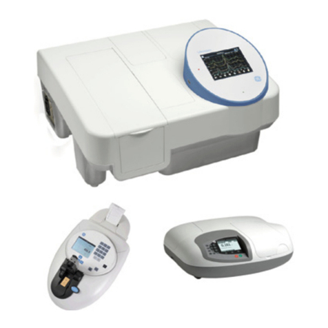
GE Moisture Image 1 Series User manual

-~
ARTISAN
®
~I
TECHNOLOGY
GROUP
Your definitive source
for
quality
pre-owned
equipment.
Artisan Technology
Group
Full-service,
independent
repair
center
with
experienced
engineers
and
technicians
on staff.
We
buy
your
excess,
underutilized,
and
idle
equipment
along
with
credit
for
buybacks
and
trade-ins
.
Custom
engineering
so
your
equipment
works
exactly as
you
specify.
•
Critical
and
expedited
services
•
Leasing
/
Rentals/
Demos
• In
stock/
Ready-to-ship
•
!TAR-certified
secure
asset
solutions
Expert
team
ITrust
guarantee
I
100%
satisfaction
All
tr
ademarks,
br
a
nd
names, a
nd
br
a
nd
s a
pp
earing here
in
are
th
e property of
th
e
ir
r
es
pecti
ve
ow
ner
s.
Visit our website - Click HERE

Moisture Image Series 1
Service Manual

June 2003
Process Control Instruments
Moisture Image Series 1
Hygrometer
Service Manual 910-108SB
!ATTENTION!
This manual contains instructions for Series 1 units
equipped with the latest controller card (p/n 703-
1250). This controller card supports the PanaCom/
PanaView user interface software.

iii
June 2003
Warranty Each instrument manufactured by GE Panametrics is warranted to be
free from defects in material and workmanship. Liability under this
warranty is limited to restoring the instrument to normal operation or
replacing the instrument, at the sole discretion of GE Panametrics. Fuses
and batteries are specifically excluded from any liability. This warranty
is effective from the date of delivery to the original purchaser. If GE
Panametrics determines that the equipment was defective, the warranty
period is:
•one year for general electronic failures of the instrument
•one year for mechanical failures of the transducers
If GE Panametrics determines that the equipment was damaged by
misuse, improper installation, the use of unauthorized replacement parts,
or operating conditions outside the guidelines specified by GE
Panametrics, the repairs are not covered under this warranty.
The warranties set forth herein are exclusive and are in lieu of
all other warranties whether statutory, express or implied
(including warranties or merchantability and fitness for a
particular purpose, and warranties arising from course of
dealing or usage or trade).
Return Policy If a GE Panametrics instrument malfunctions within the warranty period,
the following procedure must be completed:
1. Notify GE Panametrics, giving full details of the problem, and
provide the model number and serial number of the instrument. If the
nature of the problem indicates the need for factory service, GE
Panametrics will issue a RETURN AUTHORIZATION NUMBER
(RAN), and shipping instructions for the return of the instrument to a
service center will be provided.
2. If GE Panametrics instructs you to send your instrument to a service
center, it must be shipped prepaid to the authorized repair station
indicated in the shipping instructions.
3. Upon receipt, GE Panametrics will evaluate the instrument to
determine the cause of the malfunction.
Then, one of the following courses of action will then be taken:
•If the damage is covered under the terms of the warranty, the
instrument will be repaired at no cost to the owner and returned.
•If GE Panametrics determines that the damage is not covered under
the terms of the warranty, or if the warranty has expired, an estimate
for the cost of the repairs at standard rates will be provided. Upon
receipt of the owner’s approval to proceed, the instrument will be
repaired and returned.


v
June 2003
Table of Contents
Chapter 1: Installing Optional Features
Making Electrical Connections . . . . . . . . . . . . . . . . . . . . . . . . . . . . . . . . . . . . . . . . . . . . . . . . . . .1-1
Installation Instructions for CE Mark Conformity . . . . . . . . . . . . . . . . . . . . . . . . . . . . . . . . .1-2
Precautions for Modified or Non-GE Panametrics Cables . . . . . . . . . . . . . . . . . . . . . . . . . . .1-3
Connecting the Recorder Outputs . . . . . . . . . . . . . . . . . . . . . . . . . . . . . . . . . . . . . . . . . . . . . . . . .1-4
Accessing the Channel Cards . . . . . . . . . . . . . . . . . . . . . . . . . . . . . . . . . . . . . . . . . . . . . . . . .1-4
Setting the Switch Blocks . . . . . . . . . . . . . . . . . . . . . . . . . . . . . . . . . . . . . . . . . . . . . . . . . . . .1-4
Replacing the Channel Card . . . . . . . . . . . . . . . . . . . . . . . . . . . . . . . . . . . . . . . . . . . . . . . . . .1-5
Connecting the Recorders. . . . . . . . . . . . . . . . . . . . . . . . . . . . . . . . . . . . . . . . . . . . . . . . . . . .1-5
Connecting the Alarms . . . . . . . . . . . . . . . . . . . . . . . . . . . . . . . . . . . . . . . . . . . . . . . . . . . . . . . . .1-6
Connecting Pressure Sensor Inputs . . . . . . . . . . . . . . . . . . . . . . . . . . . . . . . . . . . . . . . . . . . . . . . .1-8
Connecting a Pressure Transducer . . . . . . . . . . . . . . . . . . . . . . . . . . . . . . . . . . . . . . . . . . . . .1-9
Connecting Pressure Transmitters . . . . . . . . . . . . . . . . . . . . . . . . . . . . . . . . . . . . . . . . . . . .1-11
Connecting Auxiliary Inputs (Optional) . . . . . . . . . . . . . . . . . . . . . . . . . . . . . . . . . . . . . . . . . . .1-16
Accessing the Channel Cards . . . . . . . . . . . . . . . . . . . . . . . . . . . . . . . . . . . . . . . . . . . . . . . .1-17
Replacing the Channel Card . . . . . . . . . . . . . . . . . . . . . . . . . . . . . . . . . . . . . . . . . . . . . . . . .1-17
Connecting a Personal Computer or Printer . . . . . . . . . . . . . . . . . . . . . . . . . . . . . . . . . . . . . . . .1-18
Setting the RS232 Switch . . . . . . . . . . . . . . . . . . . . . . . . . . . . . . . . . . . . . . . . . . . . . . . . . . .1-18
Connecting the PC or Printer . . . . . . . . . . . . . . . . . . . . . . . . . . . . . . . . . . . . . . . . . . . . . . . .1-19
Performing an MH Calibration Test/Adjustment . . . . . . . . . . . . . . . . . . . . . . . . . . . . . . . . . . . .1-20
Preliminary Steps . . . . . . . . . . . . . . . . . . . . . . . . . . . . . . . . . . . . . . . . . . . . . . . . . . . . . . . . .1-20
Calibration Procedure . . . . . . . . . . . . . . . . . . . . . . . . . . . . . . . . . . . . . . . . . . . . . . . . . . . . . .1-20

June 2003
vi
Table of Contents (cont.)
Chapter 2: Troubleshooting and Maintenance
Introduction . . . . . . . . . . . . . . . . . . . . . . . . . . . . . . . . . . . . . . . . . . . . . . . . . . . . . . . . . . . . . . . . . 2-1
Testing the Alarm Relays. . . . . . . . . . . . . . . . . . . . . . . . . . . . . . . . . . . . . . . . . . . . . . . . . . . . . . . 2-2
Testing the Recorder Outputs. . . . . . . . . . . . . . . . . . . . . . . . . . . . . . . . . . . . . . . . . . . . . . . . . . . . 2-3
Procedure for Testing the Recorder Output. . . . . . . . . . . . . . . . . . . . . . . . . . . . . . . . . . . . . . 2-4
Trimming Recorder Outputs . . . . . . . . . . . . . . . . . . . . . . . . . . . . . . . . . . . . . . . . . . . . . . . . . . . . 2-5
Preliminary Steps. . . . . . . . . . . . . . . . . . . . . . . . . . . . . . . . . . . . . . . . . . . . . . . . . . . . . . . . . . 2-5
Procedure for Trimming the Zero Value . . . . . . . . . . . . . . . . . . . . . . . . . . . . . . . . . . . . . . . . 2-6
Procedure for Trimming the Span Value. . . . . . . . . . . . . . . . . . . . . . . . . . . . . . . . . . . . . . . . 2-9
Screen Messages . . . . . . . . . . . . . . . . . . . . . . . . . . . . . . . . . . . . . . . . . . . . . . . . . . . . . . . . . . . . 2-10
Common Problems. . . . . . . . . . . . . . . . . . . . . . . . . . . . . . . . . . . . . . . . . . . . . . . . . . . . . . . . . . . 2-12
Checking/ Replenishing the Delta F Oxygen Cell Electrolyte. . . . . . . . . . . . . . . . . . . . . . . . . . 2-14
Adding or Removing a PCMCIA Card . . . . . . . . . . . . . . . . . . . . . . . . . . . . . . . . . . . . . . . . . . . 2-16
Procedure for Adding or Removing a PCMCIA Card . . . . . . . . . . . . . . . . . . . . . . . . . . . . 2-16
Installing a Channel Card. . . . . . . . . . . . . . . . . . . . . . . . . . . . . . . . . . . . . . . . . . . . . . . . . . . . . . 2-19
Replacing and Recalibrating the Moisture Probes. . . . . . . . . . . . . . . . . . . . . . . . . . . . . . . . . . . 2-20
Recalibrating the Pressure Sensors . . . . . . . . . . . . . . . . . . . . . . . . . . . . . . . . . . . . . . . . . . . . . . 2-20
Calibrating the Delta F Oxygen Cell . . . . . . . . . . . . . . . . . . . . . . . . . . . . . . . . . . . . . . . . . . . . . 2-21
Displaying the Oxygen Content in PPMv and µA . . . . . . . . . . . . . . . . . . . . . . . . . . . . . . . 2-21
Checking the Oxygen Cell Calibration . . . . . . . . . . . . . . . . . . . . . . . . . . . . . . . . . . . . . . . . 2-23
Entering the New Span Value . . . . . . . . . . . . . . . . . . . . . . . . . . . . . . . . . . . . . . . . . . . . . . . 2-24
Delta F Oxygen Cell Background Gas Correction Factors . . . . . . . . . . . . . . . . . . . . . . . . . . . . 2-25
Correcting for Different Background Gases . . . . . . . . . . . . . . . . . . . . . . . . . . . . . . . . . . . . 2-25
Entering the Current Multiplier . . . . . . . . . . . . . . . . . . . . . . . . . . . . . . . . . . . . . . . . . . . . . . 2-26
Range Error Description . . . . . . . . . . . . . . . . . . . . . . . . . . . . . . . . . . . . . . . . . . . . . . . . . . . . . . 2-28
Signal Error Description . . . . . . . . . . . . . . . . . . . . . . . . . . . . . . . . . . . . . . . . . . . . . . . . . . . . . . 2-28
Calibration Error Description. . . . . . . . . . . . . . . . . . . . . . . . . . . . . . . . . . . . . . . . . . . . . . . . . . . 2-28

vii
June 2003
Table of Contents (cont.)
Appendix A: Application of the Hygrometer (900-901D1)
Introduction . . . . . . . . . . . . . . . . . . . . . . . . . . . . . . . . . . . . . . . . . . . . . . . . . . . . . . . . . . . . . . . . . A-1
Moisture Monitor Hints. . . . . . . . . . . . . . . . . . . . . . . . . . . . . . . . . . . . . . . . . . . . . . . . . . . . . . . . A-2
Pressure . . . . . . . . . . . . . . . . . . . . . . . . . . . . . . . . . . . . . . . . . . . . . . . . . . . . . . . . . . . . . . . . . A-3
Response Time . . . . . . . . . . . . . . . . . . . . . . . . . . . . . . . . . . . . . . . . . . . . . . . . . . . . . . . . . . . A-3
Temperature . . . . . . . . . . . . . . . . . . . . . . . . . . . . . . . . . . . . . . . . . . . . . . . . . . . . . . . . . . . . . A-4
Flow Rate . . . . . . . . . . . . . . . . . . . . . . . . . . . . . . . . . . . . . . . . . . . . . . . . . . . . . . . . . . . . . . . A-4
Contaminants. . . . . . . . . . . . . . . . . . . . . . . . . . . . . . . . . . . . . . . . . . . . . . . . . . . . . . . . . . . . . . . . A-5
Non-Conductive Particulates . . . . . . . . . . . . . . . . . . . . . . . . . . . . . . . . . . . . . . . . . . . . . . . . A-5
Conductive Particulates. . . . . . . . . . . . . . . . . . . . . . . . . . . . . . . . . . . . . . . . . . . . . . . . . . . . . A-6
Corrosive Particulates . . . . . . . . . . . . . . . . . . . . . . . . . . . . . . . . . . . . . . . . . . . . . . . . . . . . . . A-6
Aluminum Oxide Probe Maintenance. . . . . . . . . . . . . . . . . . . . . . . . . . . . . . . . . . . . . . . . . . . . . A-7
Corrosive Gases And Liquids . . . . . . . . . . . . . . . . . . . . . . . . . . . . . . . . . . . . . . . . . . . . . . . . . . . A-9
Materials of Construction . . . . . . . . . . . . . . . . . . . . . . . . . . . . . . . . . . . . . . . . . . . . . . . . . . . . . A-10
Calculations and Useful Formulas in Gas Applications . . . . . . . . . . . . . . . . . . . . . . . . . . . . . . A-11
Nomenclature . . . . . . . . . . . . . . . . . . . . . . . . . . . . . . . . . . . . . . . . . . . . . . . . . . . . . . . . . . . A-11
Parts per Million by Volume. . . . . . . . . . . . . . . . . . . . . . . . . . . . . . . . . . . . . . . . . . . . . . . . A-12
Parts per Million by Weight . . . . . . . . . . . . . . . . . . . . . . . . . . . . . . . . . . . . . . . . . . . . . . . . A-13
Relative Humidity. . . . . . . . . . . . . . . . . . . . . . . . . . . . . . . . . . . . . . . . . . . . . . . . . . . . . . . . A-13
Weight of Water per Unit Volume of Carrier Gas . . . . . . . . . . . . . . . . . . . . . . . . . . . . . . . A-13
Weight of Water per Unit Weight of Carrier Gas. . . . . . . . . . . . . . . . . . . . . . . . . . . . . . . . A-14
Comparison of PPMV Calculations . . . . . . . . . . . . . . . . . . . . . . . . . . . . . . . . . . . . . . . . . . A-21
Liquid Applications . . . . . . . . . . . . . . . . . . . . . . . . . . . . . . . . . . . . . . . . . . . . . . . . . . . . . . . . . . A-22
Theory of Operation . . . . . . . . . . . . . . . . . . . . . . . . . . . . . . . . . . . . . . . . . . . . . . . . . . . . . . A-22
Moisture Content Measurement in Organic Liquids. . . . . . . . . . . . . . . . . . . . . . . . . . . . . . A-22
Empirical Calibrations. . . . . . . . . . . . . . . . . . . . . . . . . . . . . . . . . . . . . . . . . . . . . . . . . . . . . . . . A-28
Solids Applications . . . . . . . . . . . . . . . . . . . . . . . . . . . . . . . . . . . . . . . . . . . . . . . . . . . . . . . . . . A-34
Appendix B: Certifications

Chapter 1

Installing Optional Features
Making Electrical Connections . . . . . . . . . . . . . . . . . . . . . . . . . . . .1-1
Connecting the Recorder Outputs . . . . . . . . . . . . . . . . . . . . . . . . .1-4
Connecting the Alarms . . . . . . . . . . . . . . . . . . . . . . . . . . . . . . . . . .1-6
Connecting Pressure Sensor Inputs . . . . . . . . . . . . . . . . . . . . . . .1-8
Connecting Auxiliary Inputs (Optional) . . . . . . . . . . . . . . . . . . . .1-16
Connecting a Personal Computer or Printer . . . . . . . . . . . . . . . .1-18
Performing an MH Calibration Test/ Adjustment. . . . . . . . . . . . .1-20

Installing Optional Features 1-1
June 2003
Making Electrical
Connections
In addition to moisture probes and oxygen cells, the Moisture Image
Series 1 can support a variety of optional equipment: recorders,
alarms, pressure sensor inputs, auxiliary inputs, PCs and printers.
Make all connections to the back panel of the meter. The panel is
separated into six sections, one for each channel. Figure 1-1 shows
this back panel.
Note: The power line is the main disconnect device.For compliance
with the EU’s Low Voltage Directive (IEC 1010), this unit
requires an external power disconnect device such as a switch
or circuit breaker. The disconnect device must be marked as
such, clearly visible, directly accessible, and located within
1.8 m (6 ft) of the Series 1.
!WARNING!
TO ENSURE THE SAFE OPERATION OF THIS UNIT,
YOU MUST INSTALL AND OPERATE THE SERIES 1
AS DESCRIBED IN THIS SERVICE MANUAL. IN
ADDITION, BE SURE TO FOLLOW ALL
APPLICABLE SAFETY CODES AND REGULATIONS
FOR INSTALLING ELECTRICAL EQUIPMENT IN
YOUR AREA.
!WARNING!
DIVISION 2 APPLICATIONS MAY REQUIRE
SPECIAL INSTALLATION. CONSULT THE
NATIONAL ELECTRIC CODE FOR PROPER
INSTALLATION REQUIREMENTS. THE ANALYZER
MUST BE CONFIGURED IN A SUITABLE
EQUIPMENT ENCLOSURE AND INSTALLED PER
THE NATIONAL ELECTRIC CODE ARTICLE 500
APPLICABLE SECTIONS WHICH PERTAIN TO THE
HAZARDOUS ENVIRONMENT CLASSIFICATION IN
WHICH THE ELECTRONICS WILL BE USED.
Figure 1-1: Series 1 Back Panel
ALM A
A
BA REC
C
ALM A
NO NC
ALM B
AUX
RTN 1
RTN NO
2 +24V
NCCNO
737
STD/TF
PROBE
9
8
OXYGEN
59
4 8
5
6
3
4
1
22
15
2 6
3
4
1 1
2
ALM A
AUX
1
NO
+24V
NC
RTN
RECB
NCCRTN
AUX
12
ALM B
NO C
REC
ALM A
A
NO C
BRTN
RTNNC RTN
+24V2
ALM B
CNC
REC
AB
ALM A
NO C NC
ALM B
RTN 12
AUX
NO C
+24V A
NC NO
ALM B
AUX
+24V
RTN
B
REC
NCCRTN
AUX
12
ALM B
NO CNC NC
REC
A
ALM A
NO C
BRTN 1
RTN NO
+24V2
NCC
STD/TF
PROBE
37 37 37
OXYGEN
4
5
STD/TF
PROBE OXYGEN PROBE
STD/TF
9
8
9
8
5
4
STD/TF
PROBE OXYGEN
59
48
2
2
1
1
6
3
2
1
2
5
6
3
4
1
2
2
1 1
2
1
26
3
11
2
37 3
OXYGENOXYGEN
5
4
9
PROBE
STD/TF
8
5
4
Neut
ineL
Gnd
2
1
2
1
5
6
3
4
1
22
1
2
1
SLO-BLO
1/2 AMP
CHANNEL 1 CHANNEL 3
CHANNEL 2 CHANNEL 4 CHANNEL6
CHANNEL 5
1/2 AMP
250V
SLO-BLO
3AG
HAZARDOUS AREA
CONNECTIONS
HAZARDOUS AREA
CONNECTIONS

June 2003
1-2 Installing Optional Features
Making Electrical
Connections (cont.)
Make connections by placing the press lock lever into the desired
terminal. One press lock lever is supplied with each terminal block.
Press and hold the lever against the terminal block and insert the
stripped and tinned portion of the wire into the terminal. Release the
lever to secure the connection.
!WARNING!
TURN OFF THE SERIES 1
BEFORE MAKING ANY CONNECTIONS.
Proper connections and cabling are extremely important to accurate
measurement. Be sure to use the correct cable type for each probe and
make sure that cables are not damaged during installation. If you are
not using a GE Panametrics-supplied cable or are using a modified
cable, read the following section carefully.
ATTENTION EUROPEAN CUSTOMERS!
IN ORDER TO MEET CE MARK REQUIREMENTS,
YOU MUST INSTALL ELECTRICAL CABLES AS
DESCRIBED BELOW.
Installation Instructions
for CE Mark Conformity
NOTICE
CE MARK COMPLIANCE IS REQUIRED ONLY FOR
UNITS USED IN EEC COUNTRIES.
For CE Mark compliance, you must shield and ground the electrical
connections as shown in Table 1-1.
Note: If you make the modifications as discussed in this table, your
unit will comply with the EMC Directive 89/336/EEC.
After you make all the necessary electrical connections, seal the
unused cable entry holes with standard conduit plugs or equivalent.
Table 1-1: Wiring Modifications for CE Compliance
Connection Termination Modification
Input/Output Connect the shields to the nearest chassis
ground using the shortest run of wire possible.

Installing Optional Features 1-3
June 2003
Precautions for Modified
or Non-GE Panametrics
Cables
Many customers must use pre-existing cables, or in some cases,
modify the standard GE Panametrics-supplied moisture cable to meet
special needs. If you prefer to use your own cables or to modify our
cables, observe the precautions listed below. In addition, after
connecting the moisture probe, you must perform a calibration
adjustment as described on page 1-20 to compensate for any electrical
offsets.
Caution!
GE Panametrics cannot guarantee operation to the
specified accuracy of the Series 1 unless you use GE
Panametrics-supplied hygrometer cables.
•Use cable that matches the electrical characteristics of GE
Panametrics cable (contact the factory for specific information on
cable characteristics). The cable must have individually shielded
wire sets. A single overall shield is incorrect.
•If possible, avoid all splices. Splices will impair the performance.
When possible, instead of splicing, coil the excess cable.
•If you must splice cables, be sure the splice introduces minimum
resistive leakage or capacitive coupling between conductors.
•Carry the shield through any splice. A common mistake is to not
connect the shields over the splice. If you are modifying a GE
Panametrics cable, the shield will not be accessible without cutting
back the cable insulation. Also, do not ground the shield at both
ends. You should only ground the shield at the hygrometer end.

June 2003
1-4 Installing Optional Features
Connecting the
Recorder Outputs
The Series 1 has two optically isolated recorder outputs. These
outputs provide either a current or voltage signal, which you set using
switch blocks on the channel cards. Although the meter is configured
at the factory, you should check the switch block positions before
making connections. Use the following steps to check or reset these
switch settings:
Accessing the Channel
Cards
1. Remove the screws on the front panel and slide the electronics
unit out of its enclosure.
2. Remove the channel card by pulling the card straight up.
Setting the Switch
Blocks
1. Locate switch blocks S2 and S3 (see Figure 1-2 for switch block
S2 and S3 locations). Switch block S2 controls the output signal
for Recorder A and switch block S3 controls the output signal for
Recorder B.
2. Set the switches in the appropriate positions — I for current or V
for voltage.
3. Check or reset switches for each channel where you are using a
recorder output.
Figure 1-2: Channel Card Switch Blocks S2 and S3
S3
S2

Installing Optional Features 1-5
June 2003
Replacing the Channel
Card
1. Once the switches are set, replace the channel card.
If you intend to connect pressure inputs or other input devices to the
Series 1, do not replace the cover because you will need to set
switches on the channel card for those inputs as well.
2. Slide the electronics unit into its enclosure and replace the screws.
Tighten the screws until they are snug. Do not over tighten. You
may now connect the recorder(s).
Connecting the
Recorders
Connect the outputs to the terminal block on the lower section of the
back panel labeled REC. See Figure 1-3 for terminal block location.
Make connections for recorders using Table 1-2.
Figure 1-3: REC Terminal Block
Table 1-2: Recorder Connections
Connect Recorder A: To REC Terminal Block:
return (-) pin A-
out (+) pin A+
Connect Recorder B: To REC Terminal Block:
return (-) pin B-
out (+) pin B +
ALM A
A
BA REC
C
ALM A
NO NC
ALM B
AUX
RTN 1
RTN NO
2 +24V
NCCNO
737
STD/TF
PROBE
9
8
OXYGEN
59
4 8
5
6
3
4
1
22
15
2 6
3
4
11
2
RECB
NCCRTN
STD/TF
PROBE
CHANNEL 1
AUX
RTN 1
AL
NO C
CHAN
2
HAZARDOUS AREA
CONNECTIONS
BA REC
REC
Terminal Block

June 2003
1-6 Installing Optional Features
Connecting the Alarms You can order the Series 1 with high and low alarm relays for each
channel. Hermetically sealed alarm relays are also available. Each
alarm relay is a single-pole double-throw contact set that contains the
following contacts (see Figure 1-4):
•normally open (NO)
•normally closed (NC)
•armature contacts (C)
Make connections for the high and low alarm relays on the desired
channel(s) on the terminal blocks labeled ALM A and ALM B on the
back panel of the electronics unit. Use Table 1-3 to make high and
low alarm connections. See Figure 1-5 for the terminal block
locations.
Note: The alarm terminal block has an addition Return connection
that you can use to ground the alarms if desired.
Figure 1-4: Alarm Relay Contact Points
Table 1-3: Alarm Connections
Connect Low Alarm: To ALM A Terminal Block:
NO contact pin NO
C contact pin C
NC contact pin NC
Connect High Alarm: To ALM B Terminal Block:
NO contact pin NO
C contact pin C
NC contact pin NC
NO
C
NC

Installing Optional Features 1-7
June 2003
Connecting the Alarms
(cont.)
Figure 1-5: ALM A and ALM B Terminal Blocks
ALM A
A
BA REC
C
ALM A
NO NC
ALM B
AUX
RTN 1
RTN NO
2 +24V
NCCNO
737
STD/TF
PROBE
9
8
OXYGEN
59
4 8
5
6
3
4
1
22
15
2 6
3
4
11
2
RECB
NCCRTN
STD/TF
PROBE
CHANNEL 1
AUX
RTN 1
AL
NO C
CHAN
2
HAZARDOUS AREA
CONNECTIONS
ALM A and
ALM B
Terminal Block

June 2003
1-8 Installing Optional Features
Connecting Pressure
Sensor Inputs
The Series 1 accepts either pressure transducers or pressure
transmitters with a 0/4-20 mA or 0 to 2-V output. Each type of sensor
is connected to the meter differently; therefore it is important to know
which type of pressure sensor you are using.
IMPORTANT: The transducer must be supplied by GE Panametrics
or approved by GE Panametrics for use in this
circuit.
A pressure transducer is an electrically passive device that requires a
well-regulated excitation voltage or current. The transducer produces
a low level signal output (typically in the millivolt range) when
pressure is applied to it.
A pressure transmitter is an electrically active device containing
electronic circuits. A pressure transmitter requires some sort of power
source, such as a 24 VDC or 120 VAC. It produces an output signal
much larger than a pressure transducer’s in either current or voltage.
The more common pressure transmitters output current.
IMPORTANT: The following connection information does not
pertain to the TF Series Probe.
To properly connect a pressure sensor, use the appropriate section
that follows.

Installing Optional Features 1-9
June 2003
Connecting a Pressure
Transducer
Using a two-pair shielded cable, connect the pressure transducer to
the desired channel on the terminal block labeled STD/TF on the back
of the electronics unit (refer to Figure 1-6). Refer to Table 1-4 for the
proper pin connections for the pressure transducer. If you are not
using a GE Panametrics-supplied cable, refer to Figure 1-7 to make
the proper pin connections to the pressure transducer connector.
IMPORTANT: The transducer must be supplied by GE Panametrics
or approved by GE Panametrics for use in this
circuit.
Note: If you connect a pressure transducer to the STD/TF terminal
block, you must activate the TF Probe for that channel as
described on page 2-8 of the Startup Guide.
Figure 1-6: STD/TF Terminal Block
Table 1-4: Pressure Transducer Connections
Connect Pressure Transducer:
To STD/TF Terminal
Block:
Positive Excitation Lead (red - P1+) pin #5
Negative Excitation Lead (white - P1-) pin #6
Positive Output Lead (black - P2+) pin #7
Negative Output Lead (green - P2-) pin #8
Shield pin #9
STD/TF
Terminal Block

June 2003
1-10 Installing Optional Features
Connecting a Pressure
Transducer (cont.)
Figure 1-7: Pressure Transducer Cable Assembly
1
2
3
4
5
6
7
8
9
P1+
P1-
P2+
P2-
RTN
+
-
+
-
STD/TF PROBE
Terminal Block Probe
Red
White
Black
Green
Shield
Excitation
Output
To
Pressure
Transducer

Installing Optional Features 1-11
June 2003
Connecting Pressure
Transmitters
The Series 1 accepts two types of pressure transmitters:
Note: Optional auxiliary inputs are required.
•Two-wire or loop-powered transmitter (this is always a 4 to 20-mA
system)
•Four-wire or self-powered transmitter (this can be either a current
or voltage output system)
Connect the pressure transmitters on the desired channel(s) to the
designated pins on the AUX terminal block located on the back of the
electronics unit. Pin connections include at least one of the auxiliary
inputs (pin 1 or 2, see Figure 1-8). Because you are connecting the
sensor to one of the auxiliary inputs, you must set the corresponding
auxiliary switch to either current or voltage (refer to C. Setting Input
Switches on page 1-14).
Use the appropriate section that follows to connect a pressure
transmitter to the meter.
Figure 1-8: AUX Terminal Block Pin Designations
+-+-RTN 12+24V
Return
Auxiliary
Inputs
1
2
+24
Source
Self Powered
Loop Powered
Other manuals for Moisture Image 1 Series
2
Table of contents
Other GE Measuring Instrument manuals

GE
GE TransPort PT900 User manual

GE
GE Hydran 201i User manual

GE
GE MT144 User manual

GE
GE RHM 12 User manual

GE
GE AutoSigma 3000 DL Use and care manual

GE
GE DigitalFlow GC868 User manual

GE
GE DigitalFlow GF868 Owner's manual

GE
GE DigitalFlow GF868 Owner's manual

GE
GE Protimeter MMS User manual

GE
GE Krautkramer USM 35X User manual