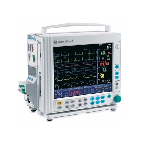
GE PDM User manual

GE Healthcare
Patient Data Module
English
2030048-001 (cd)
2030046-001A (paper)
© 2007 General Electric Company.
All rights reserved.
Patient Data Module (PDM)
Service Manual
Software version 1

T-2 Patient Data Module 2030047-001A
6 April 2007
NOTE
Due to continuing product innovation, specifications in this manual are subject to change without notice.
Listed below are GE Medical Systems Information Technologies trademarks used in this manual. All other trademarks
contained herein are the property of their respective owners.
UNITY NETWORK, DASH, SOLAR, TRAM, and TRIM KNOB are trademarks of GE Medical Systems Information
Technologies registered in the United States Patent and Trademark Office.
CARESCAPE is a trademark of GE Medical Systems Information Technologies.
For technical documentation purposes, the abbreviation GE is used for the legal entity name, GE Medical Systems
Information Technologies.

2030047-001A Patient Data Module i
Contents
1 Introduction . . . . . . . . . . . . . . . . . . . . . . . . . . . . . . . . 1-1
Manual information . . . . . . . . . . . . . . . . . . . . . . . . . . . . . . . . . . . . . . . . . . . . . 1-2
Revision history . . . . . . . . . . . . . . . . . . . . . . . . . . . . . . . . . . . . . . . . . . . . . 1-2
Manual purpose . . . . . . . . . . . . . . . . . . . . . . . . . . . . . . . . . . . . . . . . . . . . . 1-2
Intended audience . . . . . . . . . . . . . . . . . . . . . . . . . . . . . . . . . . . . . . . . . . . 1-2
Ordering manuals . . . . . . . . . . . . . . . . . . . . . . . . . . . . . . . . . . . . . . . . . . . 1-2
Safety information. . . . . . . . . . . . . . . . . . . . . . . . . . . . . . . . . . . . . . . . . . . . . . 1-2
Responsibility of the manufacturer . . . . . . . . . . . . . . . . . . . . . . . . . . . . . . 1-2
Intended use . . . . . . . . . . . . . . . . . . . . . . . . . . . . . . . . . . . . . . . . . . . . . . . 1-2
Hazard definitions . . . . . . . . . . . . . . . . . . . . . . . . . . . . . . . . . . . . . . . . . . . 1-3
Patient Data Module hazards . . . . . . . . . . . . . . . . . . . . . . . . . . . . . . . . . . 1-4
Equipment symbols . . . . . . . . . . . . . . . . . . . . . . . . . . . . . . . . . . . . . . . . . . 1-4
Service information . . . . . . . . . . . . . . . . . . . . . . . . . . . . . . . . . . . . . . . . . . . . . 1-5
Service requirements . . . . . . . . . . . . . . . . . . . . . . . . . . . . . . . . . . . . . . . . . 1-5
Equipment Identification . . . . . . . . . . . . . . . . . . . . . . . . . . . . . . . . . . . . . . 1-6
2 Equipment Overview . . . . . . . . . . . . . . . . . . . . . . . . . 2-1
Overview. . . . . . . . . . . . . . . . . . . . . . . . . . . . . . . . . . . . . . . . . . . . . . . . . . . . . . 2-2
Front view . . . . . . . . . . . . . . . . . . . . . . . . . . . . . . . . . . . . . . . . . . . . . . . . . 2-2
Rear view . . . . . . . . . . . . . . . . . . . . . . . . . . . . . . . . . . . . . . . . . . . . . . . . . . 2-3
Side view . . . . . . . . . . . . . . . . . . . . . . . . . . . . . . . . . . . . . . . . . . . . . . . . . . 2-3
Controls . . . . . . . . . . . . . . . . . . . . . . . . . . . . . . . . . . . . . . . . . . . . . . . . . . . 2-4
Indicators . . . . . . . . . . . . . . . . . . . . . . . . . . . . . . . . . . . . . . . . . . . . . . . . . . 2-4
Connector . . . . . . . . . . . . . . . . . . . . . . . . . . . . . . . . . . . . . . . . . . . . . . . . . 2-4
Basic components. . . . . . . . . . . . . . . . . . . . . . . . . . . . . . . . . . . . . . . . . . . . . . 2-5
Battery . . . . . . . . . . . . . . . . . . . . . . . . . . . . . . . . . . . . . . . . . . . . . . . . . . . . 2-5
Patient Data Module ePort host interface cable . . . . . . . . . . . . . . . . . . . . 2-5
Docking stations. . . . . . . . . . . . . . . . . . . . . . . . . . . . . . . . . . . . . . . . . . . . . 2-5
Theory of operation. . . . . . . . . . . . . . . . . . . . . . . . . . . . . . . . . . . . . . . . . . . . . 2-7
Overview . . . . . . . . . . . . . . . . . . . . . . . . . . . . . . . . . . . . . . . . . . . . . . . . . . 2-7
3 Installation . . . . . . . . . . . . . . . . . . . . . . . . . . . . . . . . . 3-1
Battery . . . . . . . . . . . . . . . . . . . . . . . . . . . . . . . . . . . . . . . . . . . . . . . . . . . . . . . 3-2
Test the battery charge . . . . . . . . . . . . . . . . . . . . . . . . . . . . . . . . . . . . . . . 3-2
Install or change the battery . . . . . . . . . . . . . . . . . . . . . . . . . . . . . . . . . . . 3-2
Software . . . . . . . . . . . . . . . . . . . . . . . . . . . . . . . . . . . . . . . . . . . . . . . . . . . . . . 3-3
Mounting options . . . . . . . . . . . . . . . . . . . . . . . . . . . . . . . . . . . . . . . . . . . . . . 3-3

ii Patient Data Module 2030047-001A
Connect to host patient monitor . . . . . . . . . . . . . . . . . . . . . . . . . . . . . . . . . . 3-5
Connect to transport bedside monitor . . . . . . . . . . . . . . . . . . . . . . . . . . . . 3-5
Connect to bedside monitor . . . . . . . . . . . . . . . . . . . . . . . . . . . . . . . . . . . . 3-5
4 Service Tool and Configuration . . . . . . . . . . . . . . . . 4-1
Overview . . . . . . . . . . . . . . . . . . . . . . . . . . . . . . . . . . . . . . . . . . . . . . . . . . . . . 4-2
Required equipment . . . . . . . . . . . . . . . . . . . . . . . . . . . . . . . . . . . . . . . . . . . . 4-2
Set up the PC . . . . . . . . . . . . . . . . . . . . . . . . . . . . . . . . . . . . . . . . . . . . . . . . . . 4-2
Connect the PC to the Patient Data Module . . . . . . . . . . . . . . . . . . . . . . . 4-2
Change the PC’s IP address . . . . . . . . . . . . . . . . . . . . . . . . . . . . . . . . . . . 4-4
Disable firewall and networking services . . . . . . . . . . . . . . . . . . . . . . . . . . 4-4
Enter the Patient Data Module service tool . . . . . . . . . . . . . . . . . . . . . . . . . 4-6
Service tool modules. . . . . . . . . . . . . . . . . . . . . . . . . . . . . . . . . . . . . . . . . . . . 4-7
Device Information . . . . . . . . . . . . . . . . . . . . . . . . . . . . . . . . . . . . . . . . . . . 4-7
Configuration . . . . . . . . . . . . . . . . . . . . . . . . . . . . . . . . . . . . . . . . . . . . . . . 4-8
Diagnostics. . . . . . . . . . . . . . . . . . . . . . . . . . . . . . . . . . . . . . . . . . . . . . . . 4-10
Calibration . . . . . . . . . . . . . . . . . . . . . . . . . . . . . . . . . . . . . . . . . . . . . . . . 4-10
5 Maintenance . . . . . . . . . . . . . . . . . . . . . . . . . . . . . . . . 5-1
Maintenance schedule . . . . . . . . . . . . . . . . . . . . . . . . . . . . . . . . . . . . . . . . . . 5-2
Manufacturer recommendations . . . . . . . . . . . . . . . . . . . . . . . . . . . . . . . . 5-2
Manufacturer responsibility . . . . . . . . . . . . . . . . . . . . . . . . . . . . . . . . . . . . 5-2
Inspection . . . . . . . . . . . . . . . . . . . . . . . . . . . . . . . . . . . . . . . . . . . . . . . . . . . . 5-2
Cleaning . . . . . . . . . . . . . . . . . . . . . . . . . . . . . . . . . . . . . . . . . . . . . . . . . . . . . . 5-3
Precautions . . . . . . . . . . . . . . . . . . . . . . . . . . . . . . . . . . . . . . . . . . . . . . . . 5-3
Cleaning procedures . . . . . . . . . . . . . . . . . . . . . . . . . . . . . . . . . . . . . . . . . 5-3
Storage . . . . . . . . . . . . . . . . . . . . . . . . . . . . . . . . . . . . . . . . . . . . . . . . . . . 5-4
Consequences of using improper cleaning product . . . . . . . . . . . . . . . . . 5-4
Cleaning products to avoid . . . . . . . . . . . . . . . . . . . . . . . . . . . . . . . . . . . . 5-4
Expansion interface cleaning . . . . . . . . . . . . . . . . . . . . . . . . . . . . . . . . . . . 5-5
Battery compartment cleaning . . . . . . . . . . . . . . . . . . . . . . . . . . . . . . . . . . 5-6
Sterilization . . . . . . . . . . . . . . . . . . . . . . . . . . . . . . . . . . . . . . . . . . . . . . . . 5-6
Battery care . . . . . . . . . . . . . . . . . . . . . . . . . . . . . . . . . . . . . . . . . . . . . . . . . . . 5-7
Use recommendations . . . . . . . . . . . . . . . . . . . . . . . . . . . . . . . . . . . . . . . . 5-7
Storage recommendations . . . . . . . . . . . . . . . . . . . . . . . . . . . . . . . . . . . . 5-7
Charge the battery . . . . . . . . . . . . . . . . . . . . . . . . . . . . . . . . . . . . . . . . . . . 5-8
Condition the battery . . . . . . . . . . . . . . . . . . . . . . . . . . . . . . . . . . . . . . . . . 5-8
Checkout procedures and NBP calibration . . . . . . . . . . . . . . . . . . . . . . . . . 5-9

2030047-001A Patient Data Module i-iii
6 Troubleshooting . . . . . . . . . . . . . . . . . . . . . . . . . . . . 6-1
Overview. . . . . . . . . . . . . . . . . . . . . . . . . . . . . . . . . . . . . . . . . . . . . . . . . . . . . . 6-2
Required tools and equipment . . . . . . . . . . . . . . . . . . . . . . . . . . . . . . . . . . 6-2
Before you begin. . . . . . . . . . . . . . . . . . . . . . . . . . . . . . . . . . . . . . . . . . . . 6-2
Problems and solutions . . . . . . . . . . . . . . . . . . . . . . . . . . . . . . . . . . . . . . . . . 6-3
Error messages . . . . . . . . . . . . . . . . . . . . . . . . . . . . . . . . . . . . . . . . . . . . . . . . 6-5
7 Field Replaceable Units . . . . . . . . . . . . . . . . . . . . . . 7-1
Ordering Parts . . . . . . . . . . . . . . . . . . . . . . . . . . . . . . . . . . . . . . . . . . . . . . . . . 7-2
Parts . . . . . . . . . . . . . . . . . . . . . . . . . . . . . . . . . . . . . . . . . . . . . . . . . . . . . . . . . 7-2
Disassembly guidelines . . . . . . . . . . . . . . . . . . . . . . . . . . . . . . . . . . . . . . . . . 7-3
Tools required . . . . . . . . . . . . . . . . . . . . . . . . . . . . . . . . . . . . . . . . . . . . . . 7-3
Before disassembly . . . . . . . . . . . . . . . . . . . . . . . . . . . . . . . . . . . . . . . . . . 7-3
Hardware precautions . . . . . . . . . . . . . . . . . . . . . . . . . . . . . . . . . . . . . . . . 7-3
Electrostatic discharge (ESD) precautions . . . . . . . . . . . . . . . . . . . . . . . . 7-3
Replacement procedures . . . . . . . . . . . . . . . . . . . . . . . . . . . . . . . . . . . . . . . . 7-4
Battery . . . . . . . . . . . . . . . . . . . . . . . . . . . . . . . . . . . . . . . . . . . . . . . . . . . . 7-4
Labels . . . . . . . . . . . . . . . . . . . . . . . . . . . . . . . . . . . . . . . . . . . . . . . . . . . . 7-5
Battery door and tray . . . . . . . . . . . . . . . . . . . . . . . . . . . . . . . . . . . . . . . . . 7-6
Mount rail and pull tab . . . . . . . . . . . . . . . . . . . . . . . . . . . . . . . . . . . . . . . . 7-7
Top housing . . . . . . . . . . . . . . . . . . . . . . . . . . . . . . . . . . . . . . . . . . . . . . . . 7-9
Main board . . . . . . . . . . . . . . . . . . . . . . . . . . . . . . . . . . . . . . . . . . . . . . . . 7-11
NBP hose, coupling and elbow . . . . . . . . . . . . . . . . . . . . . . . . . . . . . . . . 7-12
NBP assembly with manifold hose . . . . . . . . . . . . . . . . . . . . . . . . . . . . . 7-12
A Appendix A–Technical Specifications . . . . . . . . . . .A-1
Technical Specifications. . . . . . . . . . . . . . . . . . . . . . . . . . . . . . . . . . . . . . . . A-2
Physical . . . . . . . . . . . . . . . . . . . . . . . . . . . . . . . . . . . . . . . . . . . . . . . . . . .A-2
Environmental . . . . . . . . . . . . . . . . . . . . . . . . . . . . . . . . . . . . . . . . . . . . . .A-2
Battery . . . . . . . . . . . . . . . . . . . . . . . . . . . . . . . . . . . . . . . . . . . . . . . . . . . .A-2
ECG . . . . . . . . . . . . . . . . . . . . . . . . . . . . . . . . . . . . . . . . . . . . . . . . . . . . . . A-3
Respiration . . . . . . . . . . . . . . . . . . . . . . . . . . . . . . . . . . . . . . . . . . . . . . . . A-5
Temperature . . . . . . . . . . . . . . . . . . . . . . . . . . . . . . . . . . . . . . . . . . . . . . .A-5
Invasive blood pressure . . . . . . . . . . . . . . . . . . . . . . . . . . . . . . . . . . . . . . .A-6
Non-invasive blood pressure . . . . . . . . . . . . . . . . . . . . . . . . . . . . . . . . . . .A-7
Pulse oximetry (Sp02) . . . . . . . . . . . . . . . . . . . . . . . . . . . . . . . . . . . . . . . . A-9
Cardiac output . . . . . . . . . . . . . . . . . . . . . . . . . . . . . . . . . . . . . . . . . . . . .A-10
Certifications . . . . . . . . . . . . . . . . . . . . . . . . . . . . . . . . . . . . . . . . . . . . . .A-10
Warranty . . . . . . . . . . . . . . . . . . . . . . . . . . . . . . . . . . . . . . . . . . . . . . . . .A-11
i-iv Patient Data Module 2030047-001A
B Appendix B– Electromagnetic Compatibility . . . . .B-1
Electromagnetic compatibility (EMC) . . . . . . . . . . . . . . . . . . . . . . . . . . . . . B-2
Guidance and manufacturer’s declaration – electromagnetic emissions B-2
Guidance and manufacturer’s declaration – electromagnetic immunity B-3
Recommended separation distances . . . . . . . . . . . . . . . . . . . . . . . . . . . . . B-4
Compliant cables and accessories . . . . . . . . . . . . . . . . . . . . . . . . . . . . . . . B-5

2030047-001A Patient Data Module 1-1
1
Introduction

1-2 Patient Data Module 2030047-001A
Introduction
Manual information
Revision history
Each page of this manual has the document part number and revision letter at the
bottom of the page. The revision letter identifies the document’s update level. The
revision history of this document is summarized below.
Manual purpose
This manual provides technical information for service representatives and technical
personnel for maintaining the equipment.
Intended audience
This manual is intended for service representatives and technical personnel who
install, configure, maintain, administer, troubleshoot, or repair this equipment.
Ordering manuals
A paper copy of this manual will be provided upon request. Contact your local GE
representative and request the part number on the first page of the manual.
Safety information
Responsibility of the manufacturer
GE is responsible for the effects of safety, reliability, and performance only if:
Assembly operations, extensions, readjustments, modifications, or repairs are
carried out by persons authorized by GE.
The electrical installation of the relevant room complies with the requirements of
the appropriate regulations.
The equipment is used in accordance with the instructions for use.
Intended use
This device is intended for use under the direct supervision of a licensed health care
practitioner.
This device is not intended for home use.
Federal law restricts this device to be sold by or on the order of a physician.
Revision Comments
A Initial release.

Introduction
2030047-001A Patient Data Module 1-3
Contact GE for information before connecting any devices to the equipment that are
not recommended in this manual.
Parts and accessories used must meet the requirements of the applicable IEC 60601
series safety standards, and/or the system configuration must meet the requirements
of the IEC 60601 medical electrical systems standard.
Periodically, and whenever the integrity of the device is in doubt, test all functions.
The use of accessory equipment not complying with the equivalent safety
requirements of this equipment may lead to a reduced level of safety of the resulting
system. Consideration relating to the choice shall include:
use of the accessory in the patient vicinity; and
evidence that the safety certification of the accessory has been performed in
accordance to the appropriate IEC 60601-1 and/or IEC 60601-1-1 harmonized
national standard.
If the installation of the equipment, in the USA, will use 240V rather than 120V, the
source must be a center-tapped, 240V, single-phase circuit.
Hazard definitions
Warnings and Cautions are used throughout this manual and designate a degree or
level of hazardous situations. A hazard is defined as a source of potential injury to a
person.
DANGER
DANGER— indicates an imminent hazard which, if not avoided,
will result in death or serious injury.
WARNING
WARNING— indicates a potential hazard or unsafe practice which,
if not avoided, could result in death or serious injury.
CAUTION
CAUTION— indicates a potential hazard or unsafe practice which,
if not avoided, could result in minor personal injury or product/
property damage.
NOTE
A NOTE provides application tips or other useful information.

1-4 Patient Data Module 2030047-001A
Introduction
Patient Data Module hazards
WARNING
ACCIDENTAL SPILLS—To avoid electric shock or device
malfunction liquids must not be allowed to enter the device. If
liquids have entered a device, take it out of service and have it
checked by a service technician before it is used again.
Equipment symbols
The following symbols appear on the equipment.
ATTENTION: Consult accompanying documents before using the
equipment.
Defibrillator-proof type CF equipment; type CF equipment is specifically
designed for applications where a conductive connection directly to the
heart is established. The paddles indicate the equipment is defibrillator
proof.
Defibrillator-proof type BF equipment; type BF equipment is specifically
designed for applications intentional external and internal application to the
patient, excluding direct cardiac application. Type BF equipment is type B
equipment with an F-type isolated (floating) part. The paddles indicate the
equipment is defibrillator proof.
Medical Equipment
With respect to electric shock, fire and mechanical hazards only in
accordance with UL 60601-1, CAN/CSA C22.2 NO. 601.1, IEC 60601-1,
IEC 60601-2-27, IEC 60601-2-30, IEC 60601-2-34, and IEC 60601-2-49.
This symbol indicates that the waste of electrical and electronic equipment
must not be disposed as unsorted municipal waste and must be collected
separately. Please contact an authorized representative of the
manufacturer for information concerning the decommissioning of your
equipment.
This symbol indicates the date of manufacture of this device. The first four
digits identify the year and the last two digits identify the month.
4P41
2006-08

Introduction
2030047-001A Patient Data Module 1-5
Service information
Service requirements
Refer equipment servicing to GE’s authorized service personnel only.
Any unauthorized attempt to repair equipment under warranty voids that
warranty.
It is the user’s responsibility to report the need for service to GE Medical
Systems Information Technologies or to one of their authorized agents.
Failure on the part of the responsible individual, hospital, or institution using this
equipment to implement a satisfactory maintenance schedule may cause undue
equipment failure and possible health hazards.
Regular maintenance, irrespective of usage, is essential to ensure that the
equipment is always functional when required.
Battery
Communication
Power
ePort connection
Zero all

1-6 Patient Data Module 2030047-001A
Introduction
Equipment Identification
Every GE Medical Systems Information Technologies device has a unique serial
number for identification. A sample of the information found on a serial number label
is shown below.
Description
1Product code1
1
Product code for the Patient Data Module is
SA3
.
2 Year manufactured
3 Fiscal week manufactured
4 Production sequence number
5 Manufacturing site
6 Miscellaneous characteristic
### ## ## #### # #
123456

2030047-001A Patient Data Module 2-1
2
Equipment Overview

2-2 Patient Data Module 2030047-001A
Equipment Overview
Overview
The Patient Data Module is a data acquisition device for a GE modular system. It
provides a connection from the host monitor to the patient, processes the patient data
signals and stores a limited amount of patient data (24 hours captured at 1 minute
resolution) for seamless transport.
Front view
404B
1 Expansion cover (expansion mount for future expansion
modules)
2 Communication icon and indicator
3 Power icon and indicator
4 Power ON/IBP Zero All button
5 Patient cable connectors
6Defib/Sync (for auxiliary equipment)
213
564

Equipment Overview
2030047-001A Patient Data Module 2-3
Rear view
405B
Side view
406A
1 ePort host interface connection
2 Battery door
1
2
1 Expansion cover
2 Docking station
3 Pull tab
1
23

2-4 Patient Data Module 2030047-001A
Equipment Overview
Controls
The power/zero all key has a dual role as a power on and zero all.
Power on — Turns the data acquisition function ON. Power is derived from a
battery or patient monitor. When turned on, the function changes to the zero all
function.
Zero all — Zeros all invasive pressure lines which are open to atmosphere. Each
pressure can also be zeroed, if desired, with a menu option in the pressure menu.
Indicators
Communication
The following LED condition identifies the communication status with a bedside or
transport patient monitor.
No light indicates no communication.
Solid amber indicates an application reset.
Solid green indicates communication.
Flashing amber indicates communication failure.
Alternately flashing with the power LED indicates software transfer.
Power
The following LED condition identifies the power status.
No light indicates no power applied.
Solid amber indicates software booting up.
Solid green indicates powered by AC-derived mains or battery.
Flashing amber indicates approximately five minutes battery power remaining.
Alternately flashing with the communication LED indicates software transfer.
Connector
Patient Data Modules connect to a bedside or transport patient monitor using the host
interface connector. It carries power, communication, and analog output signals to the
display device.

Equipment Overview
2030047-001A Patient Data Module 2-5
Basic components
Battery
The Patient Data Module is designed to operate on battery power when used with a
transport monitor or whenever AC power is interrupted. A complete battery
management system allows you to obtain maximum battery performance. When
connected to a bedside monitor, audible and visual alarms alert you when loss of
power is imminent, and on-screen capacity gauges on the transport monitor indicate
battery charge condition and capacity.
Patient Data Module ePort host interface cable
The Patient Data Module ePort host interface cable provides external power and
communication between the Patient Data Module and a patient or transport monitor.
Docking stations
There are three versions of docking stations:
Bedside dock for use with Solar 8000M/i patient monitor.
Transport dock for use with Transport Pro patient monitor.
Fixed mount adapter (mini dock) for use with mounting hardware.
Patient Data Module bedside dock
The Patient Data Module bedside dock is used for mounting the Patient Data Module
to a bedside patient monitor. It has a host interface connection which delivers power,
provides communication and allows easy connection with a patient monitor.
Patient Data Module transport dock
The Patient Data Module transport dock is attached to a transport patient monitor
when it ships from the factory. It is fastened to the back of the transport patient
monitor and delivers power, provides communication and allows easy connection and
disconnection.
Patient Data Module fixed mount adapter (mini dock)
The Patient Data Module fixed mount adapter provides a mechanical connection
between the Patient Data Module and mounting hardware. There are no electrical
connections on the mini dock.

2-6 Patient Data Module 2030047-001A
Equipment Overview
Views
Patient Data Module bedside dock.
480A
Patient Data Module fixed mount adapter (mini dock).
481A

Equipment Overview
2030047-001A Patient Data Module 2-7
Theory of operation
Overview
The Patient Data Module is a portable acquisition device. It collects data from a
patient, converts the data to a digital form for processing, and sends the data to a
bedside, transport or surgical monitor for further processing and display.
The data that it collects, converts, and sends includes the patient’s vital signs and
physiological waveforms. It also stores patient history including trends and special
events, and setup information such as blood pressure zero points and alarm limit
settings. The patient history is stored so that the collected information is transferred
when a patient is transferred to a different monitor.
413B
The Patient Data Module shares power and communicates with host devices through
the host interface connection called the ePort. The Patient Data Module connects
directly to a transport patient monitor through a docking station. The Patient Data
Module connects to a bedside host patient monitor through the host interface cable
and docking station.
The Patient Data Module contains software and hardware to monitor the following
parameters:
ECG/respiration
Noninvasive blood pressure
Pulse oximetry

2-8 Patient Data Module 2030047-001A
Equipment Overview
Up to four channels of invasive blood pressure and cardiac output or two
channels of temperature.
Defibrillator sync/analog out interface
Table of contents
Other GE Medical Equipment manuals

GE
GE T8 User manual

GE
GE Innova Series User manual

GE
GE iVent 201 Series Assembly instructions

GE
GE TONOPORT VI User manual

GE
GE Giraffe OmniBed Carestation CS1 User manual

GE
GE Vacugene User manual

GE
GE Voluson 730 User manual

GE
GE Voluson 730 User manual

GE
GE Responder AED Operation manual

GE
GE Definium AMX 700 User manual
Popular Medical Equipment manuals by other brands

Erbe
Erbe VIO 200 D Service manual

Welch Allyn
Welch Allyn Spot Vision Screener VS100 Directions for use

Access Sensor Technologies
Access Sensor Technologies UPAS v2 user manual

Melten
Melten M2 Nurse Call Module user guide

Hitachi
Hitachi C22P instruction manual

Sirona
Sirona CEREC MC XL operating instructions