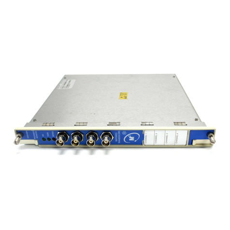
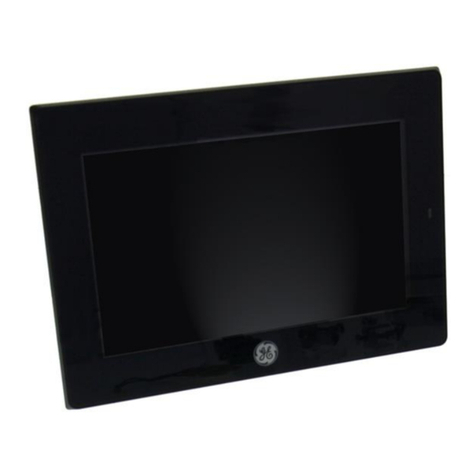
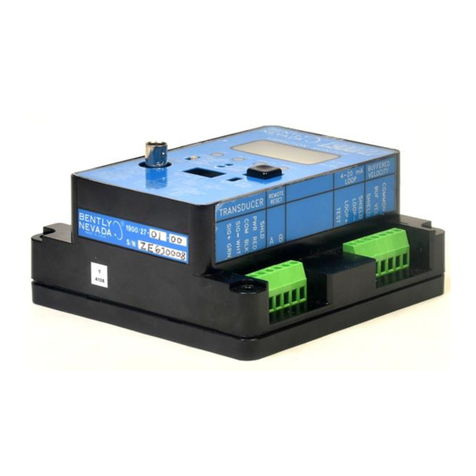
GE Bently Nevada 3300/25 User manual

Part Number 80181-01
Rev. AA (08/07)
Bently Nevada™ Asset Condition Monitoring
Operation Manual
3300/25 Dual Accelerometer Input
Monitor

3300/25 Dual Accelerometer Input Monitor Operation Manual
ii
Copyright © 1987. Bently Nevada LLC.
All rights reserved.
The information contained in this document is subject to change without notice.
The following are trademarks of General Electric Company in the United States and other
countries:
ACM, Actionable Information, Actionable Information to the Right People at the Right
Time, ADRE, Asset Condition Management, Asset Condition Monitoring, Because Better
Machines Begin With Better Bearings, Bently ALIGN, Bently BALANCE, Bently DOCUVIEW,
Bently LUBE, Bently PERFORMANCE, Bently Nevada, CableLoc, ClickLoc, Data Manager,
Decision SupportSDemoNet, Dynamic Data Manager, Engineer Assist, FieldMonitor,
flexiTIM, FluidLoc, Helping You Protect and Manage All Your Machinery, HydroScan,
HydroView, Key ∅, Keyphasor, Machine Condition Manager 2000, MachineLibrary,
Machine Manager, MicroPROX, Move Data, Not People, Move Information, Not Data, NSv,
Prime Spike, PROXPAC, Proximitor, REBAM, RuleDesk, SE, Seismoprobe, ServoFluid, Smart
Monitor, Snapshot, System 1, System Extender, TDXnet, TDIXconnX, TipLoc, TorXimitor,
Transient Data Manager, Trendmaster, TrimLoc, Velomitor
Contact Information
The following ways of contacting Bently Nevada are provided for those times when you
cannot contact your local representative:
Mailing Address 1631 Bently Parkway South
Minden, Nevada USA 89423
USA
Telephone 1.775.782.3611
1.800.227.5514
Fax 1.775.215.2873
Internet www.ge-energy.com/bently

iii
Additional Information
Notice:
This manual does not contain all the information required to operate and maintain
the product. Refer to the following manuals for other required information.
3300 System Overview (Part Number 80171-01)
3300 System Installation Instructions (Part Number 80172-01)
3300 System Troubleshooting (Part Number 80173-01)
3300/12 Power Supply (AC supply) (Part Number 89602-01)
3300/14 Power Supply (DC supply) (Part Number 101256-01)
3300/03 System Monitor (Part Number 89604-01)
3300 Internal Barriers, Installation Manual (Part Number 88837-01)
RELATED PARTS
3300/25 Field Wiring Diagram Packet (Part Number 100317-01)
3300/25 Data Sheet (Part Number 141501-01)
3300/25 Meter Scales (Part Number 84113-25)
Product Disposal Statement
Customers and third parties, who are not member states of the European Union, who are
in control of the product at the end of its life or at the end of its use, are solely
responsible for the proper disposal of the product. No person, firm, corporation,
association or agency that is in control of product shall dispose of it in a manner that is
in violation of any applicable federal, state, local or international law. Bently Nevada LLC
is not responsible for the disposal of the product at the end of its life or at the end of its
use.

3300/25 Dual Accelerometer Input Monitor Operation Manual
iv
In this document procedures are given only for channel A. Procedures for channel B are
similar except for the obvious substitutions of corresponding switches, terminals, and
indicators.
NOTE: The information in this manual pertains to monitor main boards with part number
105513-xx and 79552-xx (all revisions) and filter boards with part numbers 148921-01
(all revisions), 105521-01 (all revisions and 79562-01 revision J and later. Exceptions are
noted in the appropriate sections.
SYMBOLS
Special symbols are used in the manual to illustrate specifics in the step-by-step
processes.

v
Contents
1. Dual Accelerometer Monitor System ................................................................... 1
2. Monitor Functions ................................................................................................ 2
3. LED Functionality................................................................................................. 6
3.1 OK LEDs........................................................................................................ 6
3.2 Bypass LEDs ................................................................................................. 7
3.3 Alert LEDs...................................................................................................... 8
3.4 Danger LEDs ................................................................................................. 9
4. Read Channel Values........................................................................................ 10
5. Read Setpoint Levels......................................................................................... 11
6. Monitor Removal and Disassembly ................................................................... 12
7. Monitor Disassembly ......................................................................................... 13
7.1 Filter and Expander Board Removal............................................................ 13
7.1.1 Filter Board Removal..................................................................... 14
7.1.2 Expander Board Removal ............................................................. 14
7.2 Front Panel Removal ................................................................................... 15
7.3 Signal Input Relay Module Removal............................................................ 16
7.4 Signal Input Relay Modules (SIRM)............................................................. 17
7.5 No Relay and Dual Relay SIRM................................................................... 18
7.6 Quad Relay Signal Input Module Options.................................................... 19
7.7 Internal Barrier Options SIRM...................................................................... 20
8. Monitor Options ................................................................................................. 21
8.1 Field Programmable Options ....................................................................... 21
8.2 Monitor Ordering Options ............................................................................ 22
9. Meter Scale Replacement ................................................................................. 24
10. Alarm Setpoint Adjustment ................................................................................ 25
11. Channel Bypass................................................................................................. 26
12. Danger Bypass .................................................................................................. 27
13. Test Alarms........................................................................................................ 28
13.1 Connect and Adjust the Test Instruments ................................................. 29
13.2 Test the Alert Setpoint Level ..................................................................... 31
13.3 Test the Danger Setpoint Level................................................................. 32
13.4 Prepare to Bring the Monitor On Line........................................................ 33
14. Test OK Limits ................................................................................................... 34
15. Calibrate Channels ............................................................................................ 37
15.1 Set the Filter Option to No Filters .............................................................. 38
15.2 Connect and Adjust the Test Instruments ................................................. 39
15.3 Calibrate the Channels.............................................................................. 40
15.4 Prepare to Bring the Monitor On Line........................................................ 41
16. Self Test............................................................................................................. 42
17. Error Codes ....................................................................................................... 46
18. Appendix A–Main Board Options....................................................................... 47
18.1 Jumper Locations for PWA 105513-xx...................................................... 47
18.2 Shipped As Options................................................................................... 48
18.3 Main Board Option Settings ...................................................................... 49
18.4 Recorder Options ...................................................................................... 50
18.5 Channel Types .......................................................................................... 51
18.6 Full Scale Options ..................................................................................... 52
18.7 Main Board Buffered Out and Filter Options ............................................. 53
3300/25 Dual Accelerometer Input Monitor Operation Manual
vi
19. Appendix B–Filter Board Options PWA 79562-01 and PWA 105521-01 ...........54
19.1 Identify Filter Board ....................................................................................54
19.2 Filter Board Jumper Locations ...................................................................55
19.3 Integrator/Gain Stage Flow Path................................................................56
19.4 General Procedure.....................................................................................57
19.5 Filter Board Options ...................................................................................58
19.6 Integrator/Gain Stage Options ...................................................................59
19.7 High Pass Filter Options ............................................................................61
19.8 Non Standard High Pass Filter Options .....................................................63
19.9 Example High-Pass Filter Configuration ....................................................64
19.10 Low-Pass Freq. Configuration Table........................................................66
19.11 Non Standard Low Pass Filter Options ....................................................70
19.11.1 Setting the Anti-Aliasing Filter ....................................................70
19.11.2 Setting the Low-Pass Corner Frequency....................................72
19.12 Divider Ratio Table...................................................................................74
19.13 Example Low-Pass Filter Configuration ...................................................75
19.14 Band-Pass Filters.....................................................................................78
19.15 Test Filter Option......................................................................................79
19.16 Test Filter Option (Alternate Procedure) ..................................................83
20. Appendix C–Filter Board Options PWA 148921-01...........................................86
20.1 Identify Filter Board ....................................................................................86
20.2 Filter Board Jumper Locations ...................................................................87
20.3 Integrator/Gain Stage Flow Path................................................................88
20.4 General Procedure.....................................................................................89
20.5 Filter Board Options ...................................................................................90
20.6 Integrator/Gain Stage Options ...................................................................91
20.7 High Pass Filter Options ............................................................................93
20.8 Non Standard High Pass Filter Options .....................................................95
20.9 Example High-Pass Filter Configuration ....................................................96
20.10 Low Pass Filter Options ...........................................................................98
20.11 Band-Pass Filters...................................................................................128
20.12 Test Filter Option....................................................................................129
20.13 Test Filter Option (Alternate Procedure) ................................................133
21. Appendix D–Integrated Signals ........................................................................136
21.1 Integrator Response.................................................................................136
21.2 Integrated Buffered Output Calculation....................................................137
21.2.1 Sample Calculation, Buffered Output .......................................138
21.2.2 Derivation of Integrated Signal Voltage....................................138
21.3 Integrated Meter Reading Calculations....................................................139
21.3.1 Conversion Factor Calculation .................................................140
21.3.2 Sample Calculation, Meter Output ...........................................141
21.4 Calc. of Input for Full Scale Integrated Output .........................................141
22. Recommended Spare Parts .............................................................................142
23. Index.................................................................................................................143

Section 1 - Dual Accelerometer Monitor System
1
1. Dual Accelerometer Monitor System
Do not use this figure as a wiring diagram. Refer to 3300/25 Field Wiring Packet.

3300/25 Dual Accelerometer Input Monitor Operation Manual
2
2. Monitor Functions
DUAL ACCELEROMETER INPUT - The 3300/25 Dual Accelerometer Input Monitor
provides two independent channels of on-line machine monitoring using accelerometers
for the transducer inputs. Accelerometers are generally used for high frequency
measurements on machines such as turbines, gear boxes, compressors, and pumps.
The monitor has filtering capabilities (high-pass, low-pass, band pass) that are
programmable for selected frequency components or ranges.
SINGLE ACCELEROMETER INPUT - The 3300/25 Dual Accelerometer Input Monitor can
also be used with a single transducer input. In this mode you can use both channels to
monitor the same transducer but using different signal processing on each channel. You
can choose to have channel A display in acceleration units and channel B in velocity
units. You can also use different filter configurations on each channel.
OK - When the transducer output voltage is within the upper and lower OK limits of the
monitor, the transducer is defined as OK. The detection circuit controls the channel OK
and the monitor relay drive to the System OK Relay. If the monitor has the latching OK
option enabled, a system reset is required to reset the OK function.
TIMED OK/CHANNEL DEFEAT - Timed OK/Channel Defeat minimizes false alarms due to
faulty transducer wiring. If the input signal level on a given channel is not within the
upper and lower OK limits, the following events occur:
the OK LED for the channel goes off,
the BYPASS LED for the channel comes on,
the channel is disabled, and
the System OK Relay de-energizes.
If the channel input signal level is restored within the upper and lower OK limits for 30
seconds, the channel OK LED starts flashing at 1 Hz to indicate that the OK state is
restored, the BYPASS LED goes off, and monitoring is enabled. Press the RESET switch on
the front of the System Monitor to stop the OK LED from flashing (it will remain on and
steady after you press the RESET switch).
If the channel remains not OK, you can put the channel out of service by setting a
channel bypass switch on the monitor circuit board. The monitor can then be operated
as a single channel monitor. Without this feature the OK Relay could not be reactivated
when faulty transducer wiring causes a not OK condition. In the Timed OK/Channel
Defeat and Channel Bypass modes the recorder output is clamped to bottom scale and
the meter registers zero. If you select Timed OK/Channel Defeat, you must also set the
OK mode to nonlatching.

Section 2 - Monitor Functions
3
OK RELAY - The System OK Relay is mounted on the Power Input Module. Every channel
in the rack must be OK or bypassed to energize the OK Relay.
ALARM - Pressing the ALERT or DANGER switches on the monitor front panel causes the
corresponding Alert (first level alarm) or Danger (second level alarm) setpoints to be
displayed on the front panel meter. ALERT and DANGER LEDs come on when the signal
level exceeds preset levels for the selected time delay. The appropriate Alert and Danger
relay contacts are then activated. AND and OR voting logic options determine when the
Danger relay contacts are activated.
FIRST OUT - Separate First Out circuits exist for Alert and Danger alarms. A monitor with
the First Out option selected flashes a channel alarm LED if that channel was the first
channel in the rack to go into alarm since the last rack power up or reset. Pressing the
RESET switch on the System Monitor acknowledges the First Out (the LED stops flashing
and remains on steady).
DANGER BYPASS - When maintaining the monitor, you can set the Danger Bypass switch
on the monitor circuit board to inhibit the Danger relay drive. This function turns on the
BYPASS LEDs. Other front panel functions are not affected. You can enable this function
by installing a jumper on the monitor circuit board.
ALARM RELAYS - You can program monitor alarms for either latching or nonlatching
mode. In the nonlatching mode, the alarm resets automatically when the alarm
condition no longer exists. In the latching mode the alarm must be reset manually by
pressing the RESET switch on the front panel of the System Monitor (or by closing
external Reset contacts). The alarm will not reset if the alarm condition still exists.
BUFFERED OUTPUT - The monitor provides buffered signals from the transducers on the
channel A and B coaxial cable connectors on the front panel of the monitor and on
terminals on the Signal Input Relay Module. These connectors can be used to connect
external equipment to the monitor. The buffered output signal is in the same units as the
LCD display for that channel. For example, if a channel is displaying velocity units then
the corresponding buffered output will be in velocity units. The buffered output can also
be configured to output the filtered or unfiltered signal on a channel for which filters
have been configured, except for a channel which displays velocity and has the filters
before the integrator/gain stage.
RECORDER OUTPUT - The monitor provides a recorder output for each channel. The
recorder output is proportional to the measured acceleration or vibration signal over the
monitor full scale range. The output range is user selectable to be 0 to -10 Vdc, +1 to +5
Vdc, or +4 to +20 mA.
The recorder clamping option, available when the +4 to +20 mA recorder output is
selected, allows the user to choose the recorder output level used to annunciate a

3300/25 Dual Accelerometer Input Monitor Operation Manual
4
transducer not OK condition. With this option, the recorder output will clamp to either
+2mA or +4mA (user selectable) when a transducer is not OK.
TRIP MULTIPLY - The Trip Multiply function multiplies setpoints by 2X or 3X in response to
an external contact closure through terminals on the Power Input Module. When Trip
Multiply is active, the BYPASS LEDs flash and the TRIP MULTIPLY LED on the System
Monitor is on. The front panel meter and recorder outputs could saturate in this mode.
Setpoints beyond 1/3 to 1/2 of full scale may exceed OK limits when used with trip
multiply.
SELF TEST - The monitor has three levels of self test: Cyclic, Power-up, and User-invoked.
Power-up self test is performed automatically each time the monitor power is turned on.
A series of basic tests and transducer OK tests are performed.
Cyclic self test is performed automatically during monitor operation. Errors
encountered during cyclic tests disable the monitor and flash an error code on the LCD
bargraph display. If the error is intermittent, the monitor will return to operation and the
error codes will be stored for retrieval during User-invoked self tests. If the channel is OK,
the monitor indicates that error codes have been stored by flashing the OK LED at 5 Hz.
User-invoked self test performs Power-up self test and lets you read and clear error
messages that were stored during Cyclic self tests. Stored errors are annunciated by the
OK LEDs flashing at 5 Hz and the error codes displayed on the front panel LCD bargraph.
Refer to the Self Test section in this manual for further details.
ERROR CODES - Error codes are displayed on the Monitor's LCD display. The error code
display is distinguished from normal monitor operations by a fragmented scale
representation. Refer to the Self Test and Error Codes sections of this manual for more
details.
The monitor continuously indicates acceleration or velocity for Channels A and B.

Section 2 - Monitor Functions
5

3300/25 Dual Accelerometer Input Monitor Operation Manual
6
3. LED Functionality
3.1 OK LEDs
zON
{OFF
BLINK
LED DISPLAY
A B CONDITION OK RELAY
DRIVE*
zOK zChannel A and B are in operating range. ON
{OK z
zOK {
If a channel's OK LED goes off, that
channel is not OK, has been latched not
OK, or is bypassed.
OFF**
{OK {
The monitor is in self test, or both
channels are not OK or bypassed.
If an error code is displayed refer to the
Error Code section in this manual.
OFF**
OK
An LED flashing at 5 Hz indicates that an
error was encountered during Cyclic self
test. Self Test, Section 16, describes how
to read error messages.
ON
OK
OK z
zOK
An LED flashing at 1 Hz indicates that the
channel's transducer has been not OK
since the last reset. (This occurs only if
Timed OK/Channel Defeat is selected).
ON

Section 3 - LED Functionality
7
3.2 Bypass LEDs
zON
{OFF
BLINK
LED DISPLAY
A B CONDITION
zBYPASS z
The monitor is in the Danger Bypass mode.
The system is in the Power-Up mode.
User invoked Self Test is in progress.
Timed OK/Channel Defeat is active.
Both channels are bypassed.
Rack Inhibit contacts at the back of the rack closed.
{BYPASS z
zBYPASS {
If a channel's BYPASS LED comes on, that channel is
bypassed, or Timed OK/Channel Defeat is active.
BYPASS
BYPASS z
zBYPASS
If one or both BYPASS LEDs are flashing, Trip Multiply is
active. If only one LED is flashing, the other channel has
the flashing overridden by:
Channel bypass, or
Timed OK/Channel Defeat, or
Danger Bypass

3300/25 Dual Accelerometer Input Monitor Operation Manual
8
3.3 Alert LEDs
NOTE: The monitor will not annunciate an alert condition if the monitor is in the
nonlatching mode and an alert condition existed but is no longer present.
LED DISPLAY
A B CONDITION
ALERT
RELAY
DRIVE
zALERT {
{ALERT z
zALERT z
If a channel ALERT LED comes on, that
channel has exceeded its Alert setpoint
level. Read Setpoint Levels, Section 5,
describes how to read alarm setpoint
levels.
ON
{ALERT
ALERT {
A flashing ALERT LED indicates that the
channel was the first in the rack to
exceed its Alert setpoint since the last
power up or reset.
If two channel alert alarms occur within
50 milliseconds, both LEDs could flash.
ON
zON
{OFF
BLINK

Section 3 - LED Functionality
9
3.4 Danger LEDs
* If one channel in the monitor is bypassed or not OK and if the other channel then goes
into Danger, the Danger relay will be activated.
NOTE: The monitor will not annunciate a danger condition if the monitor is in the
nonlatching mode and a danger condition existed but is no longer
present.
DANGER RELAY
DRIVE
LED DISPLAY
A B CONDITION OR
Votin
g
AND
Votin
g
*
zDANGER {
{DANGER z
zDANGER z
If a channel's DANGER LED comes
on, that channel has exceeded its
Danger setpoint level. Section 5
describes how to read setpoint
levels.
ON
ON
ON
OFF
OFF
ON
{DANGER
DANGER {
A flashing DANGER LED indicates
that the channel was the first in the
rack to exceed its Danger setpoint
since the last power up or reset.
Two channels may indicate first out
following self test.
If two channel danger alarms occur
within 50 milliseconds, both LEDs
could flash.
ON
ON
OFF
OFF
zON
{OFF
BLINK

3300/25 Dual Accelerometer Input Monitor Operation Manual
10
4. Read Channel Values
The monitor continuously indicates measured acceleration or velocity. The front panel
below is indicating an acceleration of 0.9 g for channel A and 1.55 g for channel B.
Note: The meter scale units must be compatible with the full scale option
configured in Section 18.6.

Section 5 - Read Setpoint Levels
11
5. Read Setpoint Levels
Press the ALERT switch to read
the Alert setpoints for both
channel A and channel B on the
meter scale. This example has an
Alert setpoint of 1 g for channel A
and 1.7 g for channel B.
Press the DANGER switch and
read the Danger setpoints for
both channel A and channel B on
the meter scale. This example
shows a Danger setpoint of 1.8 g
for channel A and 1.85 g for
channel B.

3300/25 Dual Accelerometer Input Monitor Operation Manual
12
6. Monitor Removal and Disassembly
• Loosen two monitor retaining screws on the front of the monitor.
• Pull the monitor from the rack.
• Remove side cover by pinching the protruding tip on each standoff.
Caution
Improper rack operation may occur.
Power down rack or inhibit rack
alarms when installing or removing a
monitor.

Section 7 - Monitor Disassembly
13
7. Monitor Disassembly
7.1 Filter and Expander Board Removal
Caution
Component damage may result
from removing the filter or
expander board while power is on.
Not all Dual Accelerometer Monitors contain
the Expander Board. If this board does not
exist, its functionality has been incorporated
into the main board and connector J3 must be
j
umpered as shown

3300/25 Dual Accelerometer Input Monitor Operation Manual
14
When performing the following instructions, refer to the drawing on the previous pages.
7.1.1 Filter Board Removal
1. Disconnect J4 by pressing the connector latches outward.
2. Release all six plastic standoffs by squeezing the retaining clip while gently pulling
the filter board slightly away from the main board.
3. Remove the filter board.
7.1.2 Expander Board Removal
1. Disconnect J3 by pressing the connector latches outward.
2. Release all three plastic standoffs by squeezing the retaining clip while gently
pulling the expander board slightly away from the main board.
NOTE: The third standoff is under the ribbon cable to the right of the expander board.
3. Remove the expander board.
Caution
Component damage may result
from removing the filter or
expander board while power is on.
Table of contents
Other GE Monitor manuals

GE
GE HandHeld Display (HHD) User manual

GE
GE Dinamap PRO Series User manual

GE
GE Kelman Minitrans User manual

GE
GE Bently Nevada 3300/03 User manual

GE
GE Aritech ATS1100 User manual

GE
GE Corometrics 250cx Series User manual

GE
GE Dash 3000 User manual

GE
GE HDTV Monitor User manual

GE
GE CareScape V100 User manual

GE
GE 1926A-1AN User manual