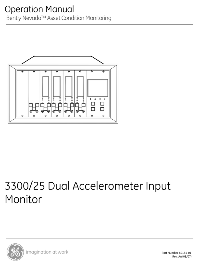
GE Bently Nevada 1900/27 User manual

Part Number 190127-01
Rev. F (09/07)
Bently Nevada™ Asset ondition Monitoring
Operation and Maintenance Manual
1900/27 Vibration Monitor

1900/27 Vibration Monitor Operation and Maintenance Manual
ii
Copyright 1994. Bently Nevada LLC.
All rights reserved.
The information contained in this document is subject to change without notice.
The following are trademarks of the legal entities cited:
Sealtite® is a registered trademark of Anamet Inc.
Teflon® is a registered trademark of DuPont.

iii
Contact Information
The following ways of contacting Bently Nevada are provided for those times when you
cannot contact your local representative:
Mailing Address 1631 Bently Parkway South
Minden, Nevada USA 89423
USA
Telephone 1.775.782.3611
1.800.227.5514
Fax 1.775.215.2873
Internet www.ge-energy.com/bently

1900/27 Vibration Monitor Operation and Maintenance Manual
iv
Additional Information
Notice:
This man al does not contain all the information req ired to operate and maintain
the prod ct. Refer to the following man als for other req ired information.
200150, 200155, and 200157 Accelerometers Information and Installation
G ide (Part N mber 164985-01)
89129 and 190520 Accelerometer User G ide (Part N mber 89134-01)
Prod ct Disposal Statement
ustomers and third parties, who are not member states of the European Union, who are
in control of the product at the end of its life or at the end of its use, are solely
responsible for the proper disposal of the product. No person, firm, corporation,
association or agency that is in control of product shall dispose of it in a manner that is
in violation of any applicable federal, state, local or international law. Bently Nevada LL
is not responsible for the disposal of the product at the end of its life or at the end of its
use.

v
Contents
1. 1900/27 Vibration Monitor Description ..................................................... 1
1.1 Features................................................................................................................................................. 1
1.2 Monitor onnections, Indicators, & ontrols.......................................................................... 4
2. Installation...................................................................................................... 6
2.1 Receiving Inspection........................................................................................................................ 6
2.2 Jumper Settings................................................................................................................................. 6
2.2.1 Setting Relays for Latching or Non-Latching Behavior............................................... 7
2.2.2 Setting Relays for Normally Energized or Normally De-energized Behavior .... 7
2.2.3 Setting 4 to 20 mA Interface Behavior During 1900/27 Monitor Bypass............ 8
2.2.4 Internal Jumper Location ......................................................................................................... 9
2.3 Monitor Enclosure.............................................................................................................................. 9
2.4 onfiguration Switch Settings...................................................................................................10
2.4.1 Relay Time Delay ........................................................................................................................10
2.4.2 Alert Relay Alarm onditions.................................................................................................10
2.4.3 onfiguring the Display for English or Metric Units ....................................................11
2.4.4 Initiating Self Test.......................................................................................................................11
2.5 onnecting Remote Reset............................................................................................................12
2.6 4 to 20 mA Interface onnections...........................................................................................12
2.6.1 onnecting able to the 1900/27 Monitor 4 to 20 mA Interface .........................12
2.7 Relay onnections ..........................................................................................................................15
2.7.1 Alert Relay onfiguration........................................................................................................16
2.7.2 Relay Internal Jumper Settings.............................................................................................17
2.7.3 Relay Electrical onnections..................................................................................................17
2.8 Power onnections ........................................................................................................................19
2.8.1 Types of Power onnections.................................................................................................19
2.8.2 Power Electrical onnections ...............................................................................................19
2.9 Field Wiring Diagram.....................................................................................................................21
3. Monitor Operation....................................................................................... 22
3.1 Monitor Display ................................................................................................................................22
3.1.1 English or Metric Display Units.............................................................................................22
3.1.2 The Display Mode Switch........................................................................................................23
3.1.3 Display Error odes ...................................................................................................................24
3.2 LED Indicators...................................................................................................................................25
3.3 Relay Mode Switch ..........................................................................................................................26
1900/27 Vibration Monitor Operation and Maintenance Manual
vi
3.4 Setpoint Adjustment ......................................................................................................................26

3.5 Resetting the Monitor.....................................................................................................................28
3.6 Buffered Transducer Output.......................................................................................................28
3.7 Initiating a Monitor Self Test........................................................................................................28
4. Maintenance & Tro bleshooting ...............................................................29
4.1 General Maintenance....................................................................................................................29
4.2 Monitor Adjustments .....................................................................................................................30
4.2.1 L D Zero Adjustment................................................................................................................30
4.2.2 Adjustment of the Monitor's 4 to 20 mA urrent Loop Interface..........................32
4.3 Troubleshooting...............................................................................................................................35
5. Appendix A - Performance Specifications................................................38
5.1 1900/27 Monitor Specification..................................................................................................38
5.1.1 Mechanical Specifications......................................................................................................38
5.1.2 Environmental Specifications...............................................................................................38
5.1.3 Monitor Power Specifications...............................................................................................40
5.1.4 Relay Specifications ..................................................................................................................40
5.1.5 Signal onditioning....................................................................................................................40
5.1.6 Accuracy.........................................................................................................................................41
5.1.7 LED Indicators..............................................................................................................................41
5.1.8 Monitor ontrols .........................................................................................................................42
5.1.9 4 to 20 mA Interface Specifications...................................................................................42
6. Appendix B - Peak Detection Methods .....................................................43
6.1 Peak Detector Theory.....................................................................................................................43
7. Appendix C - 1900/27 Monitor Config ration Form ...............................44
8. Appendix D - Accessories and Spare Parts..............................................46
8.1 Installation Hardware....................................................................................................................46
8.2 Spare Parts.........................................................................................................................................48
9. Appendix E - Hazardo s Area Approvals .................................................49

Section 1 - 1900/27 Vibration Monitor Description
1
1. 1900/27 Vibration Monitor Description
The 1900/27 Vibration Monitor provides continuous vibration monitoring for
machinery where most of the shaft vibration is transmitted through the bearing to
the case. Vibration amplitude is a primary indicator of the overall mechanical
condition of rotating machinery. Many machine malfunctions, including rotor
imbalance, misalignment, and bearing wear can be detected with vibration
measurements. Typical applications include general purpose and essential
machines with roller element bearings like pumps, fans, and compressors.
This section helps familiarize you with the monitor by listing the features that
make the monitor flexible and describing the monitor controls that make the
monitor easy to use.
1.1 Feat res
The features of the 1900/27 Vibration Monitor make the monitor more reliable
and easier to use. Many of these features have been used on previous Bently
Nevada monitors and have proven to be useful for protecting machinery. You can
program some of the features of the monitor by using jumpers or the 6-position
onfiguration switch.
Some of the non-programmable features are described below.
Transducer separate from monitor - Mounting only the transducer on the
machine requires less space and makes the transducer easier to install on
small machinery. Mounting the monitor away from the machine protects the
monitor from the harsh machine enviroment that is less suitable for
electronic instrumentation. This location makes it easier and safer for plant
personnel to access the monitor.
Digital LCD display - A digital liquid crystal display on the front of the
monitor indicates overall vibration or the Alert or Danger setpoints.
Because the monitor is designed to be mounted close to the machine rather
than on the machine, the monitor can be located where service personel
can read it easily.
Status LED indicators - Four LEDs on the front of the monitor indicate the
status of the monitor. These LEDs show whether the monitor is OK, in alarm,
or bypassed.
Remote Reset - A front panel reset button and remote reset terminals let
you reset latched relays or flashing LEDs without turning the monitor off.
The remote reset terminals allows the monitor to be reset from a remote
location without having to open the weatherproof enclosure.

1900/27 Vibration Monitor Operation and Maintenance Manual
2
Relay YPASS - A relay BYPASS switch lets you disable both relays while you
adjust the relay setpoints or maintain the machinery. This feature prevents
false alarms or undesired machinery shutdowns. When the monitor is
bypassed, the red BYPASS LED is on.
Coaxial connector - A coaxial connector on the front of the monitor
provides a buffered velocity signal (500 mV/in/s or 20 mV/mm/s) for locally
sampling dynamic data. The connector provides direct access to the
integrated transducer signal which can be used to diagnose and analyze
machinery.
Two alarm relays - The monitor has two single-pole, double-throw relays
(Type 2 FORM ). Use these relays as inputs to the machinery control
circuits, or to drive alarm annunciators such as a bell or light on an alarm
panel. You can also wire these relays together with other relays into an
AND or OR voting logic scheme. Although typically used as an Alert relays,
you can reconfigure the Alert relay to become a NOT OK relay, an Alert
logically OR'ed with NOT OK relay, or an auxiliary Danger relay. The relay
circuits include arc suppressors to increase relay contact life expectancy
and reduce arcs in hazardous locations.
4 to 20 mA Intereface - Systems set up to collect data usng a 4 to 20 mA
communications system can access the peak velocity data through this
interface.
True peak measurements - The 1900/27 Vibration Monitor uses an analog
peak-to-peak detector to determine the peak vibration amplitude. This
method is more accurate than methods which measure the RMS level and
attempt to convert it to peak value. The RMS method is poor because it
applies the conversion factor for pure sinusoidal signals even though
machinery vibration is rarely a pure sine wave (see Appendix B).
Timed OK/Monitor Defeat - This special proprietary circuit minimizes the
possibility of false alarms caused by a defective transducer, transducer
wiring, or transducer power supply.
Power-up Inhibit - This feature minimizes false alarms caused by a
transient power surge or interruption of power.
Monitor Self Test - The monitor conducts a self test which checks the
monitor's power supply voltages and verifies the signal path when you
power up the monitor or when you initiate a self test during operation of
the monitor.

Section 1 - 1900/27 Vibration Monitor Description
3
Programmable options provide flexibility and a wide range of standard features.
Internal J mper Options:
Normally Energized/De-energized Relays - The Alert and Danger relays can
be be either normally energized or normally de-energized. The normal
condition of a relay corresponds to its non-alarm condition. For example, a
normally energized relay would have power on the coil (ARM contacts NO)
when it is not in alarm and would remove power from the coil (ARM
contacts N ) when it goes into alarm. Both relays are independently set.
Latching/Nonlatching Relays - The Alert and Danger relays can be either
latching or nonlatching. Latching alarms must be cleared using the reset
button or by closing a switch between the reset terminals. Nonlatching
alarms automatically reset when the monitor no longer detects an alarm
condition. Both relays are independently set.
4 to 20 mA Interface ehavior during YPASS - When the monitor is
switched to BYPASS, the 4 to 20 mA output sends approximately 2 mA to
the host computer. Since some applications require dynamic data collection
during BYPASS, you can set the monitor so that it collects data even when
the alarms are bypassed.
Front Panel 6-position Config ration Switch Options:
Relay Time Delay - The Alert and Danger relay time delays can be set for 3,
5 , 10, or 15 seconds. Relay time delay is the amount of time that the
vibration level must be greater than the alarm setpoint level before an alarm
trips. The time delay minimizes false alarms from either "normal" transient
vibration or electrical noise sources. The relay time delay setting applies to
both relays as long as both are configured to activate under an alarm
condition.
Alert Relay Configuration - To help you use the monitor for different
applications, the Alert relay can be set to activate under any of the
following conditions:
Alert
Alert or NOT OK
NOT OK
Danger (as an auxiliary Danger relay)
Units - You can set the overall vibration level shown on the L D display to
display in either English (in/s) or metric (mm/s) units. Both units are true
zero to peak measurements, not RMS measurements converted to peak.
Monitor Self Test - A user-invoked self test switch is provided to aid in field
troubleshooting. When you invoke the self test, the signal path and alarm
threshold detection circuits are verified. All LEDs and L D numerical

1900/27 Vibration Monitor Operation and Maintenance Manual
4
segments turn on at the beginning of the self test to verify that they are
operating properly. The power supplies are checked continually.
1.2 Monitor Connections, Indicators, & Controls
The connections, LEDs and L D, and control switches are shown in the next
three figures.
Figure 1-1: Location of monitor connections

Section 1 - 1900/27 Vibration Monitor Description
5
Figure 1-2: Location of status LED indicators and L D dsplay location.
Figure 1-3: Location of monitor switches and reset button

1900/27 Vibration Monitor Operation and Maintenance Manual
6
2. Installation
This section describes how to install the 1900/27 Vibration Monitor. It includes
information on how to configure the monitor for your particular application using
the monitor's internal jumpers and the configuration switches on the front panel.
This section also describes how to connect the Accelerometer to the 1900/27
Vibration Monitor.
2.1 Receiving Inspection
Inspect the components of the order as soon as you receive them to see if there
was any damage during shipment. Keep all shipping forms and invoices. If any
shipping damage is apparent, file a claim with the carrier and submit a copy to
Bently Nevada orporation. Include all model numbers and serial numbers with
the claim. We will either repair or replace damaged parts according to the terms
and conditions of the sale.
A plastic cover will be over the display when the monitor is shipped from Bently
Nevada. Remove the cover from the label either when you receive the monitors or
during installation.
2.2 J mper Settings
Use internal jumpers to program each relay as latching or non-latching and
normally energized or de-energized. Use the Bypass Mode jumper to program
what 4 to 20 mA interface does during relay bypass.

Section 2 - Installation
7
2.2.1 Setting Relays for Latching or Non-Latching Behavior
A latching relay stays in an alarm state even after the vibration has dropped
below the setpoint level for that relay. A non latching relay moves from its alarm
state to its non-alarm state once the vibration drops back below the setpoint level
for that relay. Table 2.1 describes how to set jumpers W7 and W8 to control
latching and non latching behavior for the Alert and Danger relays.
TABLE 2.1: Latching/Non-latching Jumper
Settings
OPTION JUMPER SETTING
install remove
Alert latching* W8
Alert nonlatching W8
Danger latching* W7
Danger nonlatching W7
* Factory default setting
2.2.2 Setting Relays for Normally Energized or Normally De-energized
Behavior
The Normally Energized/De-energized option controls whether power is applied to
the relay coil during an alarm state or during a non-alarm condition. For normally
de-energized relays, no power is applied to the relay coil during non-alarm
conditions. Power is applied during alarm conditions. For normally energized
relays, power is applied to the relay coil during non-alarm conditions. Power is
removed during alarm conditions. Normally energized relays are useful when you
want to shut a machine off when vibration monitoring stops due to loss of
monitor power. Table 2.2 shows how to set jumpers W5 and W6 for Normally De-
energized or Normally Energized Alert and Danger Relays.
TABLE 2.2: Normally Energized and
Normally De-energized Jumper Settings
OPTION JUMPER SETTING
install remove
Alert Normally De-energized* W6
Alert Normally Energized W6
Danger Normally De-energized* W5
Danger Normally Energized W5
* Factory default setting

1900/27 Vibration Monitor Operation and Maintenance Manual
8
2.2.3 Setting 4 to 20 mA Interface Behavior D ring 1900/27 Monitor
Bypass
With the BYPASS Mode jumper installed the 4 to 20 mA circuit responds to a relay
bypass condition at the monitor by sending a NOT OK signal (less than 3 mA) to
the plant computer. Even though the relays are in BYPASS, the monitor remains
OK and continues to monitor vibration. The 4 to 20 mA circuit is unable to
continue sending a vibration signal when this jumper is in, but visibility of a bypass
condition is maintained at the plant computer.
With the BYPASS Mode jumper removed, bypassing the relays does not affect the
4 to 20 mA interface.
Table 2.3 shows how to use the Bypass Mode jumper to control how the 4 to 20
mA interface responds when the monitor is bypassed.
TABLE 2.3: Bypass Mode Jumper Settings
Response of the 4 to 20 mA interface when
the monitor's relays are bypassed
Bypass
mode
jumper
(W4) Flag the point as Not Transmit vibration
OK signal when relays
are bypassed
installed* yes no
removed no yes
* Factory default setting
To determine realistic setpoint values for a machine, we recommend that you
collect data for a few weeks with the relays disabled and the bypass jumper
removed. Use this configuration only long enough to collect enough data to
determine where to adjust the Alert and Danger setpoints. After you establish
realistic setpoints, install the bypass mode jumper and return to the normal
monitoring mode by placing the relay mode switch in the NORMAL positrion.

Section 2 - Installation
9
2.2.4 Internal J mper Location
Figure 2.1 shows the location of the jumpers on the monitor's circuit board.
To set the jumpers follow these steps:
1. Remove the case cover: Pull the case cover straight up. The inside of the case
cover has a label that summarizes the jumper settings.
2. Locate the five jumpers along the side of the top board (see Figure 2-1).
Figure 2-1: Location of internal jumpers.
3. Remove or insert any of the jumpers that are required for your given
application.
4. Snap the case cover back into place over the printed circuit boards.
2.3 Monitor Enclos re
Use a TYPE 4X enclosure for outdoor and lass 1, Division 2 hazardous areas. If
the monitor will be in a nonhazardous location where it is protected from the
elements, then a weatherproof enclosure is not required. Bently Nevada offers a
nonmetallic Type 4X enclosure (Bently Nevada Part Number 190100-01) or a
stainless steel RFI resistant Type 4X enclosure (Bently Nevada Part Number
03636315) for 1900 monitors. Both have windows on the front so that the L D
display of the monitor is visible from outside the enclosure. Appendix D provides
ordering information. For more information on Bently Nevada's Type 4X enclosures
for the 1900 monitor, contact your local Bently Nevada sales representative.

1900/27 Vibration Monitor Operation and Maintenance Manual
10
2.4 Config ration Switch Settings
Use the 6-position configuration switch on the front panel of the monitor to
program the relay time delays, the alert relay alarm condition, English or metric
units, and to initiate a monitor self test.
2.4.1 Relay Time Delay
Relay time delay is the amount of time that the vibration must continuously
exceed the setpoint before an alarm occurs. Table 2.4 shows the relay time delay
switch settings.
TABLE 2.4: Relay Time Delay Settings
Switch 1 Switch 2 Time Delay
Off Off 3 seconds
Off On 5 seconds
On Off 10 seconds
On On 15 seconds
2.4.2 Alert Relay Alarm Conditions
Alert relay alarm settings let you configure the Alert relay to be driven by the
following 4 conditions: the Alert setpoint, the Alert setpoint logically OR'ed with
NOT OK, NOT OK, or the Danger setpoint. If you configure the relay to be driven
from NOT OK or the Danger setpoint, the Alert setpoint is no longer used. Table 2.5
shows the Alert relay drive condition settings.
Table 2.5: Alert Relay Alarm
Condition Settings
Switch 3 Switch 4 Alert Drive
Off Off ALERT
Off On ALERT OR NOT OK
On Off NOT OK
On On DANGER

Section 2 - Installation
11
2.4.3 Config ring the Display for English or Metric Units
English/Metric Units lets you choose which measurement units are used to display
the overall vibration level on the L D as shown in Table 2.6. You may need to re-
adjust the zero of the display slightly if you change the units. Refer to section 4.2.1
to calibrate the L D zero.
Table 2.6: English/Metric
Units Settings
Switch 5 Setting Units
Off English Inches/second
On Metric Millimetres/second
2.4.4 Initiating Self Test
Initiate a Self Test by setting switch 6 to the ON position. Return switch 6 to the
OFF position once the test has started. The following actions occur during a
monitor self test, which lasts approximately 30 seconds:
• The relays are placed in their non-alarm states.
• Numerical segments of the L D turn on for the duration of the self test.
• All LEDS turn on for the first 4 seconds of the self test.
• The signal path circuits are tested
• The alarm threshold detection circuitry is tested.
If an error is detected during self test, an error code will remain on at the end of the
self test. Error codes E1 and E3 are continually tested for during normal operation.
If a power supply failure occurs, E1 comes on. If a NOT OK occurs, the OK LED
goes off and E3 comes on. Error code E2, a signal path error, can only be detected
using the self test function. The error codes are shown in Table 2.7.
Table 2.7: Self Test Error Codes
Code Error Explanation
E1 Power The internal power supply voltages are not within tolerance.
E2 Signal Path A fault exists in the vibration signal path, the alert or
danger threshold detection circuits, or the system clock.
E3 NOT OK The transducer, transducer cable, or transducer power
supply are not functioning properly.

1900/27 Vibration Monitor Operation and Maintenance Manual
12
2.5 Connecting Remote Reset
Mounting an external reset switch (or button) at a remote location lets you reset
the monitor without having to open the weatherproof housing. The remote reset
switch can be mounted up to 305 m (1000 ft) from the monitor. onnect the
remote reset switch between the REMOTE RESET A and B contacts. Use a single-
pole single-throw (SPST) type switch with normally open contacts which are
momentarily closed by the switch actuator.
2.6 4 to 20 mA Interface Connections
Systems set up to collect data using a 4 to 20 mA communication system can
access the peak velocity data through this interface. Although the 1900/27
monitor can operate without connecting the 4 to 20 mA interface, the interface
lets you collect data automatically for trending.
2.6.1 Connecting Cable to the 1900/27 Monitor 4 to 20 mA Interface
Use two-conductor shielded cable to connect the 4 to 20 mA loop power supply to
the 1900/27 Monitor. able length is restricted by the loop supply voltage, supply
source resistance, and cable impedance. The maximum cable length is determined
by:
where L is the maximum cable length in feet, Vs is the minimum loop supply
voltage, Vx is any additional voltage drop in the loop, Rs is the supply source
resistance, and Zc is the total cable impedance in ohms/ft.
(Note that the above equation accounts for the impedance of both the source
and return lines of the cable.)
The following page gives an example for calculating the maximum cable length.

Section 2 - Installation
13
Example:
Suppose your 4 to 20 mA system has the following characteristics:
• The minimum loop supply voltage is 24 V.
• The receiver has a source supply resistance of 250 ohms.
• The cable impedance is 12 milliohms/ft.
• A device with a constant voltage drop of 1 V is inserted into the loop.
Then the maximum cable length is
Use the following tools to attach the cable to the 1900/27 monitor:
• Two-conductor shielded cable.
• A screwdriver.
• A wire stripper to remove insulation from the cable
onnect the 4 to 20 mA loop to the monitor by following these steps. Refer to
Figure 2-10.
1. Strip the outer jacket and the shield foil from the monitor end of the
cable.
2. Strip 6.4 to 9.5 mm (0.250 to 0.375 in) of insulation from both of the
insulated inner conductors.
3. Use a screwdriver to connect the inner conductors including the
shield, or drain, wire to the 4 to 20 mA terminal strip.

1900/27 Vibration Monitor Operation and Maintenance Manual
14
Figure 2-10: 4 to 20 mA connections
Table of contents
Other GE Monitor manuals

GE
GE 1926A-1AN User manual

GE
GE Bently Nevada 3300/03 User manual

GE
GE IC755CS06RD Series User manual

GE
GE QuickPanel+ IC755CxS06RDx User manual

GE
GE EPM 3000P User manual

GE
GE B40 User manual

GE
GE CareScape V100 User manual

GE
GE 3500/40M User manual

GE
GE Dash 3000 User manual

GE
GE Aritech ATS1100 User manual

GE
GE Dinamap PRO Series User manual

GE
GE UVis-920 User manual

GE
GE TMO2D User manual

GE
GE Kelman Minitrans User manual

GE
GE TRANSFIX DGA 500 User manual

GE
GE Dash 3000 User manual

GE
GE IC754VBB06CTD User manual

GE
GE Responder 2000 User manual

GE
GE IC754VKI06MTD User manual

GE
GE HandHeld Display (HHD) User manual