Table of Figures
Figure 5—1: Power switch...................................................................................................................... 9
Figure 5—2: Fuse holder ........................................................................................................................ 9
Figure 5—3: Coin cell battery............................................................................................................... 10
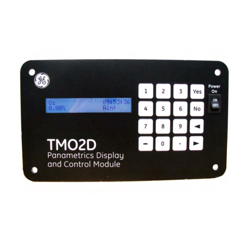
Figure 6—1: Front view of the product................................................................................................12
Figure 6—2: LCD information notice –error format (top) & example (below) ................................... 12
Figure 6—3: Boot screen...................................................................................................................... 13
Figure 6—4: Version screen ................................................................................................................. 13
Figure 6—5: Standby mode .................................................................................................................13
Figure 6—6: Scheduler disabled ..........................................................................................................13
Figure 6—7: Peripheral scheduler........................................................................................................14
Figure 6—8: Start a manual measurement ........................................................................................ 14
Figure 6—9: Stop a measurement....................................................................................................... 14
Figure 6—10: Measurement data........................................................................................................15
Figure 6—11: Standby mode ...............................................................................................................15
Figure 6—12: Communication channels............................................................................................. 16
Figure 6—13: Networking ....................................................................................................................16
Figure 6—14: GSM / GPRS modem......................................................................................................16
Figure 7—1: Manual sampling arrangement......................................................................................18
Figure 7—2: Product fitted with manual sampling arrangement......................................................18
Figure 7—3: PTFE tubing ......................................................................................................................18
Figure 7—4: Manual oil sampling process ..........................................................................................19
Figure 8—1: Air filter assembly without cover ....................................................................................20
Figure 8—2: Air filter with cover........................................................................................................... 20
Figure 9—1: Oil filter housing...............................................................................................................21
Figure 9—2: Oil filter .............................................................................................................................21
List of Tables
Table 3—1: Technical specification ....................................................................................................... 7
Table 4—1: Type tests ............................................................................................................................ 8
Table 5—1: External LED status indicators ........................................................................................... 9
Table 6—1: Error codes ........................................................................................................................17
Table A—1: Timing................................................................................................................................23
Table A—2: UNIX time registers........................................................................................................... 23
Table A—3: Access flags.......................................................................................................................24
Table A—4: Modifier flags..................................................................................................................... 24

