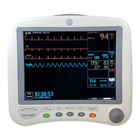
GE B40 User manual

GE Healthcare
B40/B20 Patient Monitor
HL7 Reference Manual
B40/B20 Patient Monitor
English
2062665-001 G (paper)
© 2014 General Electric Company.
All Rights Reserved.

NOTE: The information in this manual applies to GE B40/B20 Patient Monitor’s software VSP-B, VSP-C and later. It does
not apply to earlier software versions. Due to continuing product innovation, specifications in this manual are subject to
change without notice.
NOTE: For technical documentation purposes, the abbreviation GE is used for the legal entity name, GE Healthcare
Finland Oy.
Listed below are GE Medical Systems Information Technologies trademarks. All other trademarks contained herein are
the property of their respective owners.
UNITY NETWORK are trademarks of GE Medical Systems Information Technologies registered in the United States Patent
and Trademark Office.

2062665-001 G 1
Contents
1Introduction . . . . . . . . . . . . . . . . . . . . . . . . . . . . . . . . . . . 1
Manual Information . . . . . . . . . . . . . . . . . . . . . . . . . . . . . . . . . . . . . . . . . . . . . . . 2
Revision History . . . . . . . . . . . . . . . . . . . . . . . . . . . . . . . . . . . . . . . . . . . . . . . . . . . . . .2
Manual Purpose . . . . . . . . . . . . . . . . . . . . . . . . . . . . . . . . . . . . . . . . . . . . . . . . . . . . .2
Intended Audience . . . . . . . . . . . . . . . . . . . . . . . . . . . . . . . . . . . . . . . . . . . . . . . . . . .2
Manual Conventions . . . . . . . . . . . . . . . . . . . . . . . . . . . . . . . . . . . . . . . . . . . . . . . . .3
Ordering Manuals . . . . . . . . . . . . . . . . . . . . . . . . . . . . . . . . . . . . . . . . . . . . . . . . . . . .3
Service Information . . . . . . . . . . . . . . . . . . . . . . . . . . . . . . . . . . . . . . . . . . . . . . . 3
Responsibility . . . . . . . . . . . . . . . . . . . . . . . . . . . . . . . . . . . . . . . . . . . . . . . . . . . . . . . .3
Service Requirements . . . . . . . . . . . . . . . . . . . . . . . . . . . . . . . . . . . . . . . . . . . . . . . .3
Warranty . . . . . . . . . . . . . . . . . . . . . . . . . . . . . . . . . . . . . . . . . . . . . . . . . . . . . . . . . . . .3
Safety message signal words . . . . . . . . . . . . . . . . . . . . . . . . . . . . . . . . . . . . . . . . .4
2HL7 Interface . . . . . . . . . . . . . . . . . . . . . . . . . . . . . . . . . . 5
HL7 Standard Background . . . . . . . . . . . . . . . . . . . . . . . . . . . . . . . . . . . . . . . . . 6
Overview . . . . . . . . . . . . . . . . . . . . . . . . . . . . . . . . . . . . . . . . . . . . . . . . . . . . . . . . . . . .6
Multiple Segments . . . . . . . . . . . . . . . . . . . . . . . . . . . . . . . . . . . . . . . . . . . . . . . . . . .6
Data Elements . . . . . . . . . . . . . . . . . . . . . . . . . . . . . . . . . . . . . . . . . . . . . . . . . . . . . . .6
HL7 Communication . . . . . . . . . . . . . . . . . . . . . . . . . . . . . . . . . . . . . . . . . . . . . . . . .7
Observation results interfaces . . . . . . . . . . . . . . . . . . . . . . . . . . . . . . . . . . . . . . . .7
3Observation results interface . . . . . . . . . . . . . . . . . . . . 8
General Description . . . . . . . . . . . . . . . . . . . . . . . . . . . . . . . . . . . . . . . . . . . . . . . 9
Introduction . . . . . . . . . . . . . . . . . . . . . . . . . . . . . . . . . . . . . . . . . . . . . . . . . . . . . . . . .9
Trended data outbound Overview . . . . . . . . . . . . . . . . . . . . . . . . . . . . . . . . . . . .9
Low Level Communications . . . . . . . . . . . . . . . . . . . . . . . . . . . . . . . . . . . . . . . 10
Supported Numeric Options . . . . . . . . . . . . . . . . . . . . . . . . . . . . . . . . . . . . . . . 10
Supported Numeric Data Categories . . . . . . . . . . . . . . . . . . . . . . . . . . . . . . . 11
Client/Server Connections . . . . . . . . . . . . . . . . . . . . . . . . . . . . . . . . . . . . . . . . 11
HL7 Outbound . . . . . . . . . . . . . . . . . . . . . . . . . . . . . . . . . . . . . . . . . . . . . . . . . . . . . 11
HIS Disconnection or Network Outage . . . . . . . . . . . . . . . . . . . . . . . . . . . . . . 11

22062665-001 G
4PCD-01 . . . . . . . . . . . . . . . . . . . . . . . . . . . . . . . . . . . . . . 12
PCD-01 description . . . . . . . . . . . . . . . . . . . . . . . . . . . . . . . . . . . . . . . . . . . . . . . 13
IHE Patient Care Device Domain >
Device Enterprise Communication (DEC) Profile > PCD-01 Transaction . 13
OBX-4 . . . . . . . . . . . . . . . . . . . . . . . . . . . . . . . . . . . . . . . . . . . . . . . . . . . . . . . . . . . . . 14
Physiological Monitor . . . . . . . . . . . . . . . . . . . . . . . . . . . . . . . . . . . . . . . . . . . . . . . 14
Containment tree . . . . . . . . . . . . . . . . . . . . . . . . . . . . . . . . . . . . . . . . . . . . . . 14
VMD Reference IDs, MDC Codes, and Containment Trees . . . . . . . . . 16
5Sample Messages . . . . . . . . . . . . . . . . . . . . . . . . . . . . 17
HL7 minimal lower layer protocol . . . . . . . . . . . . . . . . . . . . . . . . . . . . . . . . . . 18
Interface data content . . . . . . . . . . . . . . . . . . . . . . . . . . . . . . . . . . . . . . . . . . . . 18
Transactions from the B40i monitor HL7 interface . . . . . . . . . . . . . . . . . . . 18
Result reporting messages (ORU) . . . . . . . . . . . . . . . . . . . . . . . . . . . . . . . . . . . . 18
Overview . . . . . . . . . . . . . . . . . . . . . . . . . . . . . . . . . . . . . . . . . . . . . . . . . . . . . . 18
Result Message Composition . . . . . . . . . . . . . . . . . . . . . . . . . . . . . . . . . . . 18
Result Message Examples . . . . . . . . . . . . . . . . . . . . . . . . . . . . . . . . . . . . . . 19
Application High Level Acknowledgment Messages . . . . . . . . . . . . . . . . . . 24
Overview . . . . . . . . . . . . . . . . . . . . . . . . . . . . . . . . . . . . . . . . . . . . . . . . . . . . . . 24
Acknowledgment Message Composition . . . . . . . . . . . . . . . . . . . . . . . . 24
Acknowledgment Message Examples . . . . . . . . . . . . . . . . . . . . . . . . . . . 25
6HL7 Data Segment Definitions . . . . . . . . . . . . . . . . . 27
Introduction . . . . . . . . . . . . . . . . . . . . . . . . . . . . . . . . . . . . . . . . . . . . . . . . . . . . . 28
Data Segments . . . . . . . . . . . . . . . . . . . . . . . . . . . . . . . . . . . . . . . . . . . . . . . . . . 30
MSH — Message Header Segment . . . . . . . . . . . . . . . . . . . . . . . . . . . . . . . . . . 30
MSA — Message Acknowledgment . . . . . . . . . . . . . . . . . . . . . . . . . . . . . . . . . . 31
PID — Patient Identification . . . . . . . . . . . . . . . . . . . . . . . . . . . . . . . . . . . . . . . . . 31
PV1 — Patient Visit . . . . . . . . . . . . . . . . . . . . . . . . . . . . . . . . . . . . . . . . . . . . . . . . . 33
OBR — Observation Request (To Host) . . . . . . . . . . . . . . . . . . . . . . . . . . . . . . . 35
OBX — Result . . . . . . . . . . . . . . . . . . . . . . . . . . . . . . . . . . . . . . . . . . . . . . . . . . . . . . 35
ASupported parameters . . . . . . . . . . . . . . . . . . . . . . . . . . . . 37
Supported parameters . . . . . . . . . . . . . . . . . . . . . . . . . . . . . . . . . . . . . . . . . . . . 38
HL7 Supported Parameters . . . . . . . . . . . . . . . . . . . . . . . . . . . . . . . . . . . . . . . . . 38
42062665-001 G

2062665-001 G 1
Introduction:
1Introduction

22062665-001 G
Introduction: Manual Information
Manual Information
Revision History
Each page of the document has the document part number and revision letter
at the bottom of the page. The revision letter changes whenever the document is
updated.
Manual Purpose
The device can be connected to hospital information systems (HIS) by the Health
Level Seven standard interface (HL7).
This document:
Intended to be a technical reference to GE customers implementing the HL7
outbound interface.
Not intended to provide instructions for implementing and using the HL7
standard. Details of the HL7 standard can be found in Health Level Seven
Version 2.6.
Contains data formats for the transmission of data and describes the
requirements for interfacing to the GE system using the HL7 standard.
Not describe how transactions are processed by the GE system or the
clinical impact of using some of the features described here.
Intended Audience
This manual is intended for HL7 integration engineers who configure hospital
information technology systems so they interface together.
Revision Comments
A Initial release of document
B MR release
CECOrelease
DECOrelease
EECOrelease
FECOrelease
GECOrelease

2062665-001 G 3
Introduction: Service Information
Manual Conventions
This manual uses the following styles to emphasize text or indicate action.
Ordering Manuals
To order additional copies of this manual, contact your local GE representative
and request the part number on the first page of the manual.
Service Information
Responsibility
The hospital and their third-party developer have responsibility for HL7 standard
system and environment’s integration development and testing.
Service Requirements
Follow the service requirements listed below.
For GE’s products, refer service to GE authorized service personnel only.
Any unauthorized attempt to repair equipment under warranty voids the
warranty.
For GE’s products, it is the user’s responsibility to report the need for service
to GE or to one of their authorized agents.
Failure on the part of the responsible individual, hospital, or institution using
this equipment to implement a satisfactory maintenance schedule may
cause undue equipment failure and possible health hazards.
Regular maintenance, irrespective of usage, is essential to ensure that the
equipment will always be functional when required.
Warranty
Please refer to the documentation delivered with your system for your warranty
information.
Item Description
bold Indicates hardware terms.
bold italic Indicates software terms.
italic Indicates terms for emphasis.

42062665-001 G
Introduction: Service Information
Safety message signal words
Safety message signal words designate the severity of a potential hazard.
WARNING indicates a hazardous situation that, if not avoided, could result in
death or serious injury.
CAUTION indicates a hazardous situation that, if not avoided, could result in
minor or moderate injury.
NOTICE indicates a hazardous situation not related to personal injury that, if not
avoided, could result in property damage.
The order in which safety messages are presented in no way implies the order of
importance. The following safety messages apply to the system. Safety
messages specific to parts of the system are found in the relevant section.

2062665-001 G 5
HL7 Interface: Service Information
2HL7 Interface

62062665-001 G
HL7 Interface: HL7 Standard Background
HL7 Standard Background
Overview
The Health Level Seven (HL7) standard is used to exchange data between
computer systems. It does not require a specific computer operating system,
programming language, or communication protocol for its implementation.
The goal of the HL7 standard is to harmonize message content and usage, while
allowing user-specific variations within the standard. To accomplish this, the HL7
standard specifies encoding rules used to create the message format. Based on
these rules, the messages generally consist of data fields and data segments.
Multiple Segments
A message is comprised of multiple segments. While some of the segments are
required to create a message, others are optional. Each segment within the HL7
message is separated by special segment separator characters.
Data Elements
Each segment contains various data elements. The data elements may be of
varying lengths. Like the segments, they are separated from each other by
special separator characters. Certain data elements and their separators are
logically grouped together to create a data segment such as the message
header segment or the patient identification segment. With the exception of the
segment separator characters, the data contained in HL7 messages typically
consists of displayable ASCII characters.
Each data segment begins with a three character value, for example “MSH” for
the message header segment. These three characters uniquely identify the
segment within a given message. Segments are identified as either required or
optional, and some may be repeated. Similar to data fields, data segments are
separated from each other by segment separator characters.
Based on the HL7 encoding rules, each message within the HL7 protocol has a
known structure. The data segments and data fields that comprise a given
message are always the same. As a result, an individual data field can be found
within a message simply by knowing its configured position in a segment.
Data 2Data 1 Segment mSegment 2Data n
Segment 1
Message

2062665-001 G 7
HL7 Interface: HL7 Standard Background
HL7 Communication
HL7 messages are passed between computer systems whenever a valid
transaction occurs. For example, receiving a completed test result on the
monitor system would cause an HL7 message to be generated and sent. After a
message is sent, the receiving system processes the message. When processing
is complete, the receiving system is designed to generate an application level
acknowledgment that is returned to the sending system.
Since the HL7 standard provides flexibility in message content and format, and
in communication protocol options, its implementation requires mutual
agreement between the sending and receiving computer systems on the
following items:
message formats
acknowledgment protocol
communication protocol
data handling
Communication between HIS personnel and GE interface personnel is essential
to determine the customer-specific use of the HL7 standard.
NOTE: This document is not intended to provide instructions for implementing
and using the HL7 standard. Details of the HL7 standard can be found in
Health Level Seven Version 2.6.
Observation results interfaces
The HL7 observation results reporting interface for this device is for unsolicited
trended data. ORU messages are sent unsolicited to the host at a user-
configured time interval. The monitor HL7 outbound interface pauses to wait for
an application level acknowledgment form the host. The HIS typically uses the
trended result message content in either of the following ways:
To make test results available for access on the hospital computer system.
To generate charges for completed tests.

82062665-001 G
Observation results interface: HL7 Standard Background
3Observation results
interface

2062665-001 G 9
Observation results interface: General Description
General Description
Introduction
The HL7 standard interface is used to connect a hospital’s information system
(HIS) to the monitor for the transfer of data. Using the HL7 outbound interface,
the monitor can return result messages to the HIS.
The Patient Monitor Outbound implementation of the HL7 outbound interface
protocol provides result messages. The HL7 result reporting interface transmits
the result messages to the host system.
Trended data outbound Overview
The process to create ORU message is displayed in the following diagram.
CARESCAPE Network
1. HL7 outbound from monitor though CNI V2 switch, need ‘Unity and HL7’
license

10 2062665-001 G
Observation results interface: Low Level Communications
Hospital Network
2. HL7 outbound from monitor though hospital switch, need ‘HL7’ license
NOTES
This switch should support intervlan routing function.
The hospital or the third party can choose GE offered switch or other types.
If you need to use GE offered switch, please contact to GE ND&I Team to
setup CARESCAPE Network Infrastucture version 2.
If hospital or the third party design networks by themselves, the hospital or
the third party has full responsibility for the function and the risk of their
network.
Low Level Communications
The GE HL7 interface uses TCP/IP sockets for all outbound messages and
conforms to the IEEE 802.3 Ethernet standard. The HL7 interface assumes that
the low level communication protocol ensures that the data arrives error free. As
a result, no data integrity checking is done at the application level.
Supported Numeric Options
The monitor transfers trended patient vital signs data to the hospital's
information system(s). Proper transfer of this data from the monitor to the HIS
systems is dependent on a custom configuration of the interface between the
monitor and the hospital's information system.
The monitor will send data at the configured time intervals of 1, 2, 3, 4, 5, 10, 15,
30, 45, and 60 minutes.
Hospital Intranet
CIS/HIS Systems
Internet
B40/B20
Patient Monitor
Hospital Switch
2
HL7 PCD-01
Outbound
2

2062665-001 G 11
Observation results interface: Supported Numeric Data Categories
Supported Numeric Data Categories
Support for the following data categories includes:
Invasive Blood Pressure (BP)
Gas
ECG
ECG/ST (ST)
Non-invasive Blood Pressure (NBP)
Pulse Oximetry (SPO2)
Respiration (RR)
Temperature (TP)
Entropy
Client/Server Connections
HL7 Outbound
Any HIS that communicates with the HL7 Outbound application with monitor
must act as the server. The monitor tries to open a connection on a
preconfigured specific IP address and port.
The monitor will connect with the server once the server port is established. The
monitor continuously tries to connect to the HIS on a regular periodic interval
using the auto connection feature. The monitor transfers the HL7 messages to
the HIS server by TCP/IP socket connection and will retry the message up to
three times.
When monitor already has admitted patient but no valid measurement data, the
monitor will not send out HL7 message to the EMR system.
HIS Disconnection or Network Outage
If the device or the HIS server connection is interrupted from the network (e.g.,
disconnected, in transport, etc.), the trended data for that time period will be lost.
NOTE: GE recommends that you enabling the HL7 acknowledgment option in
monitor’s service menu. Disabling this option may miss some data, if
the HL7 receiver system has the feature of sending acknowledge
message.

12 2062665-001 G
PCD-01: HIS Disconnection or Network Outage
4PCD-01

2062665-001 G 13
PCD-01: PCD-01 description
PCD-01 description
IHE Patient Care Device Domain > Device Enterprise Communication
(DEC) Profile > PCD-01 Transaction
IHE PCD-01 is an Integration Profile that simplifies and adds semantic meaning
to HL7 V2.6 messaging. The device conforms to PCD-01 as a Device Observation
Report (DOR) actor using:
ISO/IEEE 11073-10101 nomenclature in OBX-3 (Observation Identifier).
Virtual medical device containment tree in OBX-4 (Observation Sub-ID).
The originating medical device in OBX-18 (equipment instance identifier).
The value of this identifier is composed of two components. Component #1
is an EUI-64 identifier that starts with the GE Healthcare company code, plus
the EUI-64 separator, followed by the last 3 octects of the system's MAC
address in hex upper-case with no separators., plus a string that identifies
the monitoring equipment. For example, “080019FFFEAABBCCxxxxxxxx”.
Component #2 is “B40_GE”.
NOTE: The OBX-4 Observation Sub-ID follows PCD observation results
guidelines for relationships and elements in a hierarchical tree shown in
the following diagram.
Medical Device System (MDS)
Channel (Chan)
Metric
Numeric
Enumeration
Virtual Medical Device (VMD)
1
0..*
1
*
1
*
1
*

14 2062665-001 G
PCD-01: PCD-01 description
OBX-4
Condition predicate:
This field is used to distinguish between multiple OBX segments by providing an
unambiguous mapping from observation contained in the OBX segment to the
IEEE 11073 containment tree for the Medical Device System sourcing of the
observation. For device related data, this field groups devices hierarchically.
For metric related data, this field associates metrics to devices hierarchically and
is used as a sequence number within the hierarchical representation. The dotted
notation provided for in the object diagram is:
<MDS>.<VMD>.<Channel>.<Metric> for the PCD-01 transaction, where the
Metric is a sequence number.
NOTE: Numeric and Enumeration are not used for PCD-01 transactions as
shown in the object diagram.
Physiological Monitor
Containment tree
Physiological monitors are comprised of a number of different Virtual Medical
Devices (VMDs) as indicated in the following example containment tree:
The first OBX following the OBR segment is always set to:
OBX|1||69965^MDC_DEV_MON_PHYSIO_MULTI_PARAM_MDS^MDC|1
.0.0.0|||||||X
This is the standard device reference used for a monitor or monitor system.
The second OBX following OBX(1) is a Virtual Medical Device (VMD) Header, e.g.,
OBX|10||69798^MDC_DEV_ECG_VMD^MDC|1.5.0.0|||||||X
Physiological Monitor Containment tree Reference IDs
MDS: Physiological Monitor MDC_DEV_METER_PHYSIO_MULTI_PARAM_MDS (1::4301)
VMD: Blood Pressure MDC_DEV_METER_PRESS_BLD_VMD (1::4318)
Channel: Invasive BP MDC_DEV_METER_PRESS_BLD_CHAN (1::4319)
Channel: Non-Invasive BP MDC_DEV_PRESS_BLD_NONINV_CHAN (1::5151)
VMD: Temperature MDC_DEV_METER_TEMP_VMD (1::4366)
VMD: Pulse Oximeter MDC_DEV_ANALY_SAT_O2_VMD (1::4106)
VMD: ECG Monitor MDC_DEV_ECG_VMD (1::4262)
VMD: Entropy MDC_DEV_EEG_ENTROPY_VMD
This manual suits for next models
1
Table of contents
Other GE Monitor manuals

GE
GE IC754VKI06MTD User manual

GE
GE CareScape V100 User manual

GE
GE EPM 3000P User manual

GE
GE KITCHEN HUB UVH1301 User manual

GE
GE 3500/40M User manual

GE
GE Corometrics 250cx Series User manual

GE
GE Responder 2000 User manual

GE
GE CARESCAPE User manual

GE
GE TRANSFIX DGA 500 User manual

GE
GE HandHeld Display (HHD) User manual

GE
GE QuickPanel+ IC755CxS06RDx User manual

GE
GE Bently Nevada 3300/25 User manual

GE
GE HDTV Monitor User manual

GE
GE Dash 3000 User manual

GE
GE TMO2D User manual

GE
GE Bently Nevada 1900/27 User manual

GE
GE Kelman Minitrans User manual

GE
GE UVis-920 User manual

GE
GE Dinamap PRO Series User manual

GE
GE PACSystems ICRXIDIXNE19LCTA User manual