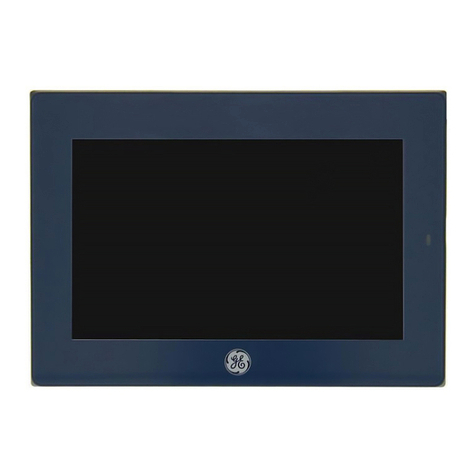
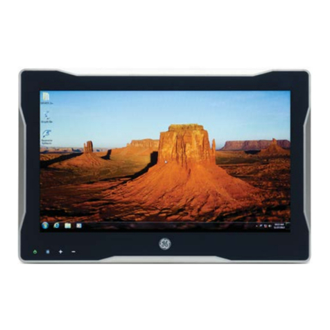
GE 1926A-1AN User manual

Use this product only after carefully reading this manual and
understanding the contents.
Keep this manual close to the display.
Confirmity according to the Council Directive 93/42/EEC concerning
Medical Devices.
MODEL NO. 1926A-1AN
Resistive - Touch
Technical MANUAL
19 Inch Color LCD

1. Revision History•••••••••••••••••••••••••••••••••••••••
2. Equipment Symbols••••••••••••••••••••••••••••••••••
3. Safety Precautions•••••••••••••••••••••••••••••••••••
4. EMC Table•••••••••••••••••••••••••••••••••••••••••••••
5. Connection Method•••••••••••••••••••••••••••••••••••
6. Adjustment Method•••••••••••••••••••••••••••••••••••
7. Compatible Signals•••••••••••••••••••••••••••••••••••
8. Specifications•••••••••••••••••••••••••••••••••••••••••
9. Cleaning Instruction••••••••••••••••••••••••••••••••••
10. FCC Information•••••••••••••••••••••••••••••••••••••
TABLE OF CONTENTS
1
2
6
9
15
19
28
31
32
33

Revision Comment
1Initial release of this document
The revision changes with related comments each time the document is updated.
RMF NO.: DOC1765836
1
Revision History

Electrical and electronic equipment symbols
Alternating current.
Atmospheric pressure limitations.
p
u
European Union Declaration of Conformity.
FCC. USA only. Complies with applicable US government
(Federal Communications Commission) radio-frequency
interference regulations.
Indicates front.
Fragile. Handle with care.
i
FRONT
w
v
Humidity limitations.
Keep dry. Protect from rain.
y
p
Date of manufacture. This symbol indicates the date of manufacture
of this device. The first four digits identify the year, the following two
digits identify the month, and the last two digits identify the day.
Eurasian Economic Union countries only. Eurasian Conformity
mark. Conformity to applicable technical regulations of
Customs Union.
2
Equipment Symbols

Recycled materials or may be recycled.
Device serial number.
Stacking limit by number.
Temperature limitations.
Underwriters Laboratories product certication mark.
Catalogue or orderable part number.
6
[
7
e
This way up.
Device hardware version.
Every device has a unique marking for identification.
The UDI marking appears on the device label
3

This symbol indicates that the waste of electrical and electronic equipment
must not be disposed as unsorted municipal waste and must be
collected separately. Please contact an authorized representative of the
manufacturer for information concerning the decommissioning of your
equipment
k
h
g
f
The LCD display complies with the China Compulsory Certification
(GB4943.1-2001, GB9254-2008, GB17625 1-2012). CCC China only.
NOTE: The following symbols (required by China law only) are
representative of what you may see on your equipment. The number
in the symbol indicates the EFUP period in years, as explained below.
Check the symbol on your equipment for its EFUP period.This symbol
indicates the product contains hazardous materials in excess of the
limits established by the Chinese standard (January 2016): GB/T
26572 Requirements for Concentration Limits for Certain Hazardous
Substances in Electronic Information Products. The number in the
symbol is the Environment-friendly User Period (EFUP), which indicates
the period during which the hazardous substances or elements
contained in electronic information products will not leak or mutate under
normal operating conditions so that the use of such electronic information
products will not result in any severe environmental pollution, any bodily
injury or damage to any assets. The unit of the period is “Year”. In order
to maintain the declared EFUP, the product shall be operated normally
according to the instructions and environmental conditions as dened in
the product manual, and periodic maintenance schedules specified in
Product Maintenance Procedures shall be followed strictly. Consumables
or certain parts may have their own label with an EFUP value less
than the product. Periodic replacement of those consumables or parts
to maintain the declared EFUP shall be done in accordance with the
Product Maintenance Procedures. This product must not be disposed
of as unsorted municipal waste, and must be collected separately and
handled properly after decommissioning.
4

ON. Power connection to the mains.
Follow instructions for use.
Standby or power indicator.
ATTENTION: Consult accompanying documents.
Power OFF.
Equipotentiality. Connect device to a potential equalization conductor.
5

6
●Make sure to carefully read the User Manual that accompanies the patient display prior
to using this display to ensure proper operation of the devices.
●Note that, excluding those cases where a responsibility for legal compensation is
recognized, the manufacturer shall bear absolutely no responsibility for damage to this
product by a customer or a third party that results in improper use from the ignoring of the
contents entered in this Technical Manual.
●Follow the instructions below for safe use of the LCD Display.
- To avoid electric shock, do not attempt to remove any cover or touch the inside of the
LCD Display. Only a qualied service technician should open the LCD Display case.
- Do not insert metal objects or spill liquid into the LCD Display through cabinet slots.
They may cause accidental fire, electric shock or failure. In case a foreign object was
inserted or water has penetrated, unplug the AC cable and have the LCD Display serviced.
- Do not cover or block the vent holes in the case.
- Disconnect the power plug from the AC outlet if you will not use it for an indenite period
of time.
- Do not apply pressure to the screen. The LCD Display is very delicate.
● No modification of this equipment is allowed. Safe use of the equipment cannot be
guaranteed if unauthorized modications are made to the display.
● If this equipment is modied, appropriate inspection and testing must be conducted to
ensure continued safe use of the equipment.
● OPERATOR must not touch the enclosure and PATIENT simultaneously.
● Do not connect to multiple socket outlets.
● To avoid the risk of electric shock this equipment must only be connected to a supply
mains with protective earth.
●If your LCD Display uses an AC/DC Adapter: Only use the Adapter, which accompanied
this device. Use of another AC/DC Adapter may cause a malfunction or electrical shock
or re hazard.
●If your LCD Display does not operate normally. In particular, if there are any unusual
sounds or smells coming from it-unplug the AC cable immediately and contact the
manufacturer, or authorized service center.
Safety Precautions
7
●POWER SUPPLY. The device must be connected to a properly installed power outlet
with protective earth contacts only. If the integrity of the protective earth conductors is in
doubt, disconnect the LCD Display from the power line and use it with the battery option if
available). If the installation does not provide for a protective earth conductor, disconnect
the LCD Display from the power line. All devices in a system must be connected to the
same power supply circuit. Devices which are not connected to the same circuit must be
electrically isolated when operated.
●GE is responsible for the effects on safety, readability, and performance of the equipment
only if:
- Assembly operations, extensions, readjustments, modications, servicing, or repairs are
carried out by authorized service personnel.
- The electrical installation of the relevant room complies with the requirements of the
appropriate regulations.
- The equipment is used in accordance with the instructions for use of the patient display
and this Technical manual.
●Grounding reliability can only be achieved when the equipment is connected to an
equivalent receptacle marked “Hospital Only” or “Hospital Grade”.
●DO NOT position the LCD Display so that it is difficult to operate or to connect and
disconnect the AC power cord.
●DO NOT touch the patient simultaneously with connection or disconnection of cables.
●Installation and OSD adjusting should only be carried by manufacturer trained and
authorized personnel.

I
CLASSIFICATION
II External Equipment
External equipment intended for connection to signal input / output or other connectors, shall
comply with IEC 60601-1 for medical electrical equipment. In addition, all such combination
systems shall comply with the standard IEC 60601-1-1, Safety requirements for medical electrical
systems. Equipment not complying with IEC 60601-1 shall be kept outside the patient
environment, as dened in the systems standard.
III Intended Use
Class I :
No applied parts
Protection against harmful ingress of water is IPX1
Not suitable for use in the presence of ammable anesthetics or oxygen.
Mode of operation: Continuous.
8
The single device output analog signals through ADC element (Analog Digital Convert)
conversion to become a digital signal and the video signal is via Video Decorder
conversion. I t has become the same digital signal, these signals via Scaler IC as zoom
in or out action and digital image processing, then through the cable line transmission
LVDS signals to one of the LCD module. The last by the clock controller (Timing Controller,
TCON), the clock signal is transmitted to the drive IC on the panel and turn on Backlight for
LCD module light source by Scaler control.
The equipment is intended to be used as a component of a medical patient monitoring
system for infant or adults by professional physician. The display shall be classified as
NON-LIFE SUPPORTING.
IV Operating Principle

EMC Table
Guidance and manufacturer’s declaration-electromagnetic immunity for all
EQUIPMENT AND SYSTEMS
Guidance and manufacturer’s declaration-electromagnetic emissions
The LCD display for Healthcare Applications is intended for use in the electromagnetic
environment specified below. The customer or the user of the LCD display for Healthcare
Applications should assure that it is used in such an environment.
Emissions test Compliance Electromagnetic environment-guidelines
RF emissions
CISPR 11
Group 1 The LCD display for Healthcare Applications uses RF
energy only for its internal function. Therefore, its RF emissions
are very low and are not likely to cause any interference in nearby
electronic equipment.
RF emissions
CISPR 11
Class A The LCD display for Healthcare Applications is suitable
for use in all establishments other than domestic and
those directly connected to a low voltage power supply network
which supplies buildings used for domestic purposes.
Harmonics
emissions
IEC 61000-3-2
Class D
Voltage
fluctuations/flicker
emissions
IEC 61000-3-3
Complies
9
EMC Table

Guidance and manufacturer’s declaration-electromagnetic immunity for all EQUIPMENT
AND SYSTEMS
Guidance and manufacturer’s declaration-electromagnetic immunity
The LCD display for Healthcare Applications is intended for use in the
electromagnetic environment specified below. The customer, or the user of the LCD display for
Healthcare Applications, should assure that it is used in such an environment.
Immunity Test
Level
IEC 60601 Compliance Level Electromagnetic Environment -
Guidelines
Electrostatic
Discharge (ESD)
IEC 61000-4-2
± 8 kV contact
± 15 kV air
± 8 kV contact
± 15 kV air
Floors should be wood, concrete
or ceramic tile. If floors are
covered with synthetic material,
the relative humidity should be at
least 30%.
Electrical Fast
Transient/Burst
IEC 61000-4-4
± 2 kV for power
supply lines
± 1 kV for
input/output lines
± 2 kV for power
supply lines
± 1 kV for
input/output
Lines
Mains power quality should be
that of a typical commercial or
hospital environment.
Surge
IEC 61000-4-5
± 1 kVline(s) to
line(s)
± 2 kV line(s) to
earth
±1kVline(s)to
line(s)
± 2 kV line(s) to
earth
Mains power quality should be
that of a typical commercial or
hospital environment.
Voltage Dips, Short
Interruption and
Voltage Variations
on Power Supply
Input Lines
IEC 61000-4-11
<5% UT
(>95% dip in UT)
for 0.5 cycle
40% UT
(60% dip in UT)
for 5 cycles
70% UT
<5% UT
(>95% dip in UT)
for 0.5 cycle
40% UT
(60 % dip in UT)
for 5 cycles
70% UT
Mains power quality should be
that of a typical commercial or
hospital environment.
If the user of the LCD display for
Healthcare Applications requires
continued operation during power
mains interruptions, It is
10

(30% dip in UT)
for 25 cycles
<5% UT
(>95% dip in UT)
for 250 cycles
(30% dip in UT)
for 25 cycles
<5% UT
(>95% dip in UT)
for 250 cycles
recommended that the LCD
display for Healthcare
Applications be powered from an
uninterruptible power supply or a
battery.
Power Frequency
(50/60 Hz)
Magnetic Field
IEC 61000-4-8
3 A/m 3 A/m Power frequency magnetic fields
should be at levels characteristic
of a typical location in a typical
commercial or hospital
environment.
NOTE UT is the A.C. mains voltage prior to application of the test level.
11

Guidance and manufacturer’s declaration-electromagnetic immunity for all EQUIPMENT
AND SYSTEMS that are not LIFE-SUPPORTING
The LCD display for Healthcare Applications is intended for use in the electromagnetic
environment specified below. The user of the LCD display for Healthcare Applications should
assure that it is used in such an environment.
Immunity Test IEC 60601 Test
Level
Compliance
Level
Electromagnetic Environment-Guidelines
Conducted RF
Radiated RF
IEC 61000-4-3
3 Vrms
3 V/m
80 MHz to 2.5
GHz
3 Vrms
3 Vrms
Portable and mobile RF communications
equipment should be used no closer to any part
of the LCD display for Healthcare Applications
and should assure that it is used in such an
environment, including cables, than the
recommended separation distance calculated
from the equation applicabl
e to the frequency of
the transmitter. Recommended separation
distance
80MHz to 800 MHz
800 MHz to 2.5GHz
where P is the maximum output power rating of
the transmitter in watts (W) according to the
Field strengths from fixed RF transmitters, as
determined by an electromagnetic site survey*1,
should be less than the compliance level in
each frequency range*2.
Interference may occur in the vicinity of
equipment marked with the following symbol:
12
transmitter manufacturer and d is the
recommended separation distance in metres(m)

* 1: At 80 MHz and 800 MHz, the higher frequency range applies.
*2: These guidelines may not apply in all situations. Electromagnetic propagation is
affected by absorption and reflection from structures, objects and people.
1.Field strengths from fixed transmitters, such as base stations for radio (cellular/cordless)
telephones and land mobile radios, amateur radio, AM and FM radio broadcast and TV
broadcast cannot be predicted theoretically with accuracy. To assess the elec
tromagnetic
environment due to fixed RF transmitters, an electromagnetic site survey should be
considered. If the measured field strength in the location in which the LCD display for
Healthcare Applications is used exceeds the applicable RF compliance leve
l above, the LCD
display for Healthcare Applications should be observed to verify normal operation. If abnormal
performance is observed, additional measures may be n ecessary, such as reorienting or
relocating the LCD display for Healthcare Applications.
2.Over the frequency range 150 kHz to 80 MHz, field strengths should be less than 3 Vrms.
13

Recommended separation distances between portable and mobile RF communications
equipment and the LCD display for Healthcare Applications for all EQUIPTMENT AND
SYSTEMS that are not LIFE-SUPPORTING
The LCD display for Healthcare Applications is intended for use in an electromagnetic
environment in which radiated RF disturbances are controlled. The customer or the user of the
LCD display for Healthcare Applications can help prevent electromagnetic interference by
maintaining a minimum distance between portable and mobile RF communications
(equipment) and the LCD display for Healthcare Applications as recommended below
according to the maximum output power of the communications equipment.
Rated Maximum
Output Power of
Transmitter
(W)
Separation Distance According to Frequency of Transmitter
150 kHz to 80 MHz 80MHzto800MHz 800MHz to 2.5 GHz
0.01 0.12 0.12 0.23
0.1 0.37 0.37 0.74
1 1.2 1.2 2.3
10 3.7 3.7 7.4
100 12 12 23
For transmitters rated at a maximum output power not listed above, the recommended separation
distanced in metres (m) can be estimated using the equation applicable to the frequency of the
transmitter, where P is the maximum output po
wer rating of the transmitter in watts (W) according to the
transmitter manufacturer.
14

1.Connect the AC power cord
provided into the display's power
input. Then, connect the plug
into an outlet.
Note
When connecting the AC power
cable, do not forget to install the
cable supplied in the accessory
box.
Connection Method
Power cord
(Accessory)
Main Power
Supply Switch
To power outlet
15

3.Connect the signal cable (for SYSTEM input).
Connect the DVI-I connector of the display and the digital output of the system with the provided
DVI-D to DVI-D cable. Do not forget to tighten the screws of the cable. The display is shipped
with the default input selected to DVI-D. The user can also select the DVI-A option if necessary.
If the NO SYNC message appears, the wrong input signal is selected. Please check the video
input and change the source input. See Page 23 for details (OSD Source Select Menu).
Use the display's DVI-I connector to make this connection. Do not forget to tighten the
screws of the cable. See Page 23 for details (OSD Source Select Menu).
Digital output of SYSTEM
Analog output of SYSTEM
OSD knob
16

4. Connect USB Cable.
Connect the system's USB TYPE A port and the displays USB TYPE B port with the
provided USB cable.
Downstream ports shall be used for accessories such as a mouse, keyboard, barcode
scanner or a remote input device. Such accessories are permitted to be connected directly
to the USB downstream port of this display.
Note:
When connecting the USB Cables do not forget to install the USB Cable Holder, as supplied in
the accessory box.
To USB Downstream port TYPE A
To USB Upstream port TYPE B
17

5. Potential Equalization Connector
If you intend to mount the display on the wall (ceiling), we strongly recommend that you use only
UL approved wall (ceiling) mount kits with attached M4*12 mm screws that can hold more than
the display weight, and that you ensure it is securely and safely installed. (VESA mounting for
75 mm x 75 mm and 100 mm x 100mm).
If you use a non-UL approved wall (ceiling) mount kit, there is a safety risk that the display
may fall from the wall (ceiling) due to an improper attachment through the use of wrong length
screws. Refer to GE manuals CARESCAPE monitors' user's manual and supplemental
information manual and to the CARESCAPE Modular Monitors Mounting Solutions for more
information on approved mounting solutions and hazards associated with improper mounting.
Note: All units are shipped with pre attached 75 mm x 75 mm VESA Plate.
Display is equipped with an equipotential connector.
6. Wall (Ceiling) VESA mounting the display.
Equipotential cable
18
Table of contents
Other GE Monitor manuals

GE
GE CARESCAPE User manual

GE
GE Dinamap PRO Series User manual

GE
GE CareScape V100 User manual

GE
GE TRANSFIX DGA 500 User manual

GE
GE Aritech ATS1100 User manual

GE
GE Bently Nevada 1900/27 User manual

GE
GE Responder 2000 User manual

GE
GE Corometrics 250cx Series User manual

GE
GE UVis-920 User manual

GE
GE IC755CS06RD Series User manual