Installation
Instructions
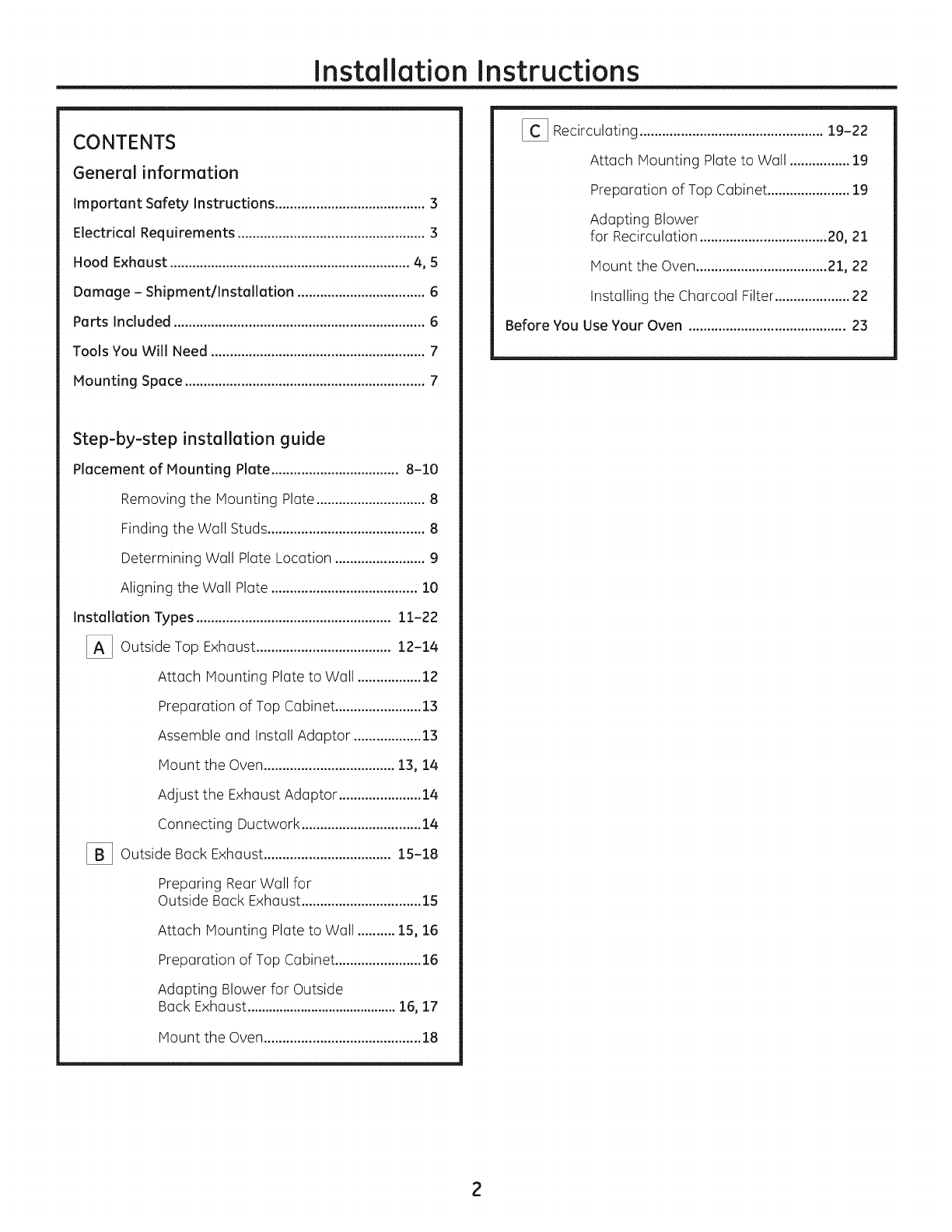
CONTENTS
General
information
Important
Safety
INStructions..................eseseseseeeeeeees
3
Electrical
Requirement
..............ccscccssssssssssesessesneeees
3
Hood
Exhaust
4,5
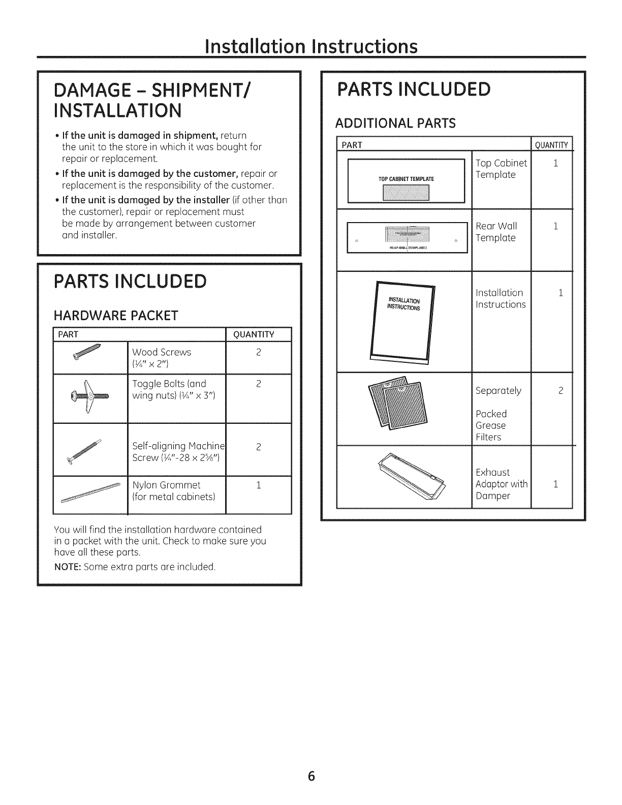
Damage
-
Shipment/Installation
oe
eeeeceseeeeees
6
Parts
Included
.
6
Tools
You
Will
Need
ou.
ees
eessscestsseeeececetstsnseseesteeeees
7
Mounting
Space
wee
7
Step-by-step
installation
guide
Placement
of
Mounting
Plate...
eeeeees
8-10
Removing
the
Mounting
Plate...
esses
8
Finding
the
Wall
Studs...
eseseseseseceseseseneneneesees
8
Determining
Wall
Plate
LOCATION
we
eeseeeeeeee
9
Aligning
the
Wall
Plate
wn
essseseeeeeeeeeees
10
installation
Types
11-22
Outside
TOp
EXNGUSt...
ee
sseseseseseseseseeeees
12-14
Attach
Mounting
Plate
to
Wall
wees
12
Preparation
of
Top
Cabinet...
cesses
13
Assemble
and
Install
Adaptor
......
esse
13
MOUNE
th
OVEN.
cecscsecsssssssssssssseseees
13,14
Adjust
the
Exhaust
Adaptor...
cesses
14
CONNECTING
DUCTWOFK.....eesesesesesseeceneeeeees
14
Outside
Back
EXNCUSt....
es
tesstssssscesteseeeeeees
15-18
Preparing
Rear
Wall
for
Outside
Back
EXNCUSt....esesssteseescesteesteeees
15
Attach
Mounting
Plate
to
Wall...
15,16
Preparation
of
Top
Cabinet...
cesses
16
Adapting
Blower
for
Outside
BOCK
EXNGUSt.wssessssssssssssssssesssessssssseseses
16,
17
MOUNE
the
OVEN
escsscseecsscssssssssessessesssssesees
18
RECIPCUIOTING
....ssececsesseseesesssesecesesececeecenseeeeees
19-22
Attach
Mounting
Plate
to
Wall
ee
19
Preparation
of
Top
Cabinet...
seen
19
Adapting
Blower
FOr
RECIFCUICTION
..ecsscssssessesssessessessesees
20,
21
MOUNE
the
OVEN.
cecscsessssssssssssesseseees
21,
22
Installing
the
Charcoal
Filters
22
Before
You
Use
Your
OV@MN
0...
eesssssecesceeeestenseeeeeees
23