GE ATS1290 User manual

© 2004 GE Security B.V. 1052285
All rights reserved 02/2005
Fig. 2
Fig. 1
Fig. 3
DGP
Lumped
X
Y
Control Panel
DGP
Distributed
X
Z
Control Panel
Star
DGP
Q
Control Panel
Remote DGP
DGP
R
Control Panel
Fig. 4
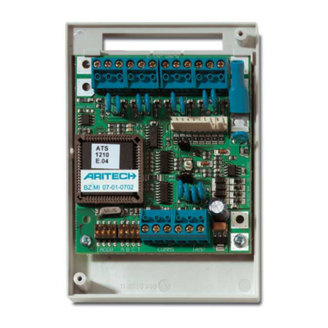
ATS1290
Point ID DGP

2
Point ID DGP Available menus
1-DGP Status
0-Exit, Menu:
Operating
*=-,#=+,0=Exit
Dev:16 A:0 T:0
*=-,#=+,0=Exit
DGP1 I:17-32 O:17-32
*=-,#=+,0=Exit
V-bus: 12,7 Vdc
*=-,#=+,0=Exit
I-bus: 3 mA
*=-,#=+,0=Exit
2-Device Status
0-Exit,Menu:
17/0,PIR,T0
Input No:
17/0, Normal
*=-,#=+,0=Exit
3-Device Settings
0-Exit,Menu:
17/0,PIR,T0
Input No:
17/0,Loc1:0
*,Value:
Or
17/0,1:00000000
*,Bits:
4-Reset Settings
0-Exit,Menu:
17/0,PIR,T0
Input No:
17/0,Reset(Y/N)?
*=Yes,#=No
5-Learn Mode
0-Exit,Menu
Start Learn Mode?
*=Yes,#=No:
6-DGP Mode
0-Exit,Menu:
1 DGP address
*=Change,#=Enter
Extended Mode
*=Change,#=Enter
7-Factory Defaults
0-Exit,Menu:
Set Factory Defaults?
*=Yes,#=No:

3
Point ID DGP
INTRODUCTION
The ATS1290 is an interface between the ATS LAN-bus and
a Point ID bus (GE proprietary Point ID protocol). The PID-
DGP provides two-wire bi-directional communications with
up to 32 individually addressed PID-devices. The ATS1290
is intended to be sitting on the LAN of any existing
configuration of ATS products to expand the system with
addressable devices. A maximum of up to 15 ATS1290
DGPs can be connected to the LAN.
MOUNTING THE UNIT
Mount the ATS1290 PCB in any existing ATS series
enclosure that supports the BB format.
CONNECTIONS CON1 (SEE FIG 1, AND )
COMMS 12 VDC power supply. It is recommended that
where the distance between an ATS1290 and the
nearest device is more than 100 meters, a
separate power supply be used. Refer to the
Remote DGP section. When using an external
power supply, use a fused power output (1 A
fast).
COMMS Positive and negative data connection of the
system databus. Units can be up to 1.5 km from
the ATS control panel, depending on the cable
used. See the ATS control panel installation guide
for details.
TAMP The PCB tamper switch is connected in parallel to
the external tamper connection. Tamper switch
requires normally open contacts.
Note: Depending on the type of housing used,
you can use the PCB tamper or connect an
external tamper.
CON10 (SEE FIG 1, )
Earth connection. Connect the shield of the ATS COMMS
cable. At the other end of the cable the shielding must be
connected to one system earth. See the ATS control panel
installation guide. This is not applicable for the possible
shielding of the PID-bus.
DGP DIPSWITCH SETTINGS (SEE FIG 1, & FIG 2)
ADDR DIP switches 1 to 4 are used to identify the DGP
number to the ATS control panel. Select the required DGP
number and set the Address DIP switch as indicated in
figure 2.
LEDS (SEE FIG 1, )
RX LED flashes to indicate polling data is being
received on the system databus from the ATS control panel.
If the LED does not flash, the control panel is not operational
or the databus is faulty (usually cabling).
TX LED flashes to indicate the DGP is replying to
polling from the ATS control panel. If the RX LED flashes
but the TX LED does not, it indicates that the DGP is not
programmed to be polled in the control panel or that it is
addressed incorrectly.
INSTALLING POINT ID DEVICES
CONNECTIONS CON2 (SEE FIG 1, & FIG 3)
PID Connection to all Point ID devices. Requires one +
and one – terminal to be connected. This will provide power
supply and data.
Devices provide for two bus terminals (see ) or only one
terminal (see & ). The bus loop does not need special
termination.
CABLE TOPOLOGY PID – BUS (SEE FIG 4)
In principle the bus-topology is free.
Shown are several topologies (see figure 4):
• Lumped (all PID-devices at the end) Distributed
(all PID-devices distributed across the line)
• Star (all devices with own branches to a star point)
• Remote DGP (A DGP positioned remote from a
power-supply)
In practice there will be a mix of topologies.
Cable types:
WN108, Unshielded, 8 core cable
WS108, Shielded, 8 core cable + shield
WCAT54: 4 pairs of FTP category 5 cable
These cables all have a core with a gauge of AWG24,
the diameter is 0.52mm and the Area is 0.22mm².
Preferred cable is the WCAT54 folowed by the WN108
and finally the WS108. In principle, use cables with as
low resistance and capacitance as possible.
If a shielded cable is used for the PID-bus, this must not
be connected to either earth, PID- or PID+. If connected,
it would result in additional capacity.
The tables below show the maximum cable lengths in
metres for different cable types. The number of devices
and device load are taken into account. Check the device-
manuals for the “Unit Load”. 1 Unit load corresponds to
300uA typical current.
Note: The absolute minimum working voltage for the PID-
bus is 9.5VDC (measured on COMMS 12VDC power supply
of the DGP). This is 1VDC under the low battery level of
10.5VDC.
The 9.5VDC is the minimum voltage for the following
situations:
1. All PID-bus powered PID-devices (Typical situation)
2. External powered PID-devices (Retrofit situation)
1. PID-devices powered out of the PID-bus
Combine 4 wires for PID+ and 4 for PID-..
Lumped and Distributed (distance X)
# Dev Unit Load WN 108 WS 108 WCAT54
32 1 1600 1200 1600
16 16 200 200 200
16 32 100 100 100
Star (distance Q)
# Dev Unit Load WN 108 WS 108 WCAT54
32 1 200 160 200
16 16 150 120 150
16 32 100 75 100
Note: By using a WN104 instead of a WN108 (cores
reduced by half), the cable lengths will be reduced by 50%.
For twisted pair cables, combine the pairs instead of
combining one core of the pair
+
-
D+
D-
Ti
Tc

4
2. External powered PID-devices (retrofit)
In this configuration, conventional detectors with additional
PID interface (AD011/AD111) are used. The detectors
themselves need to be powered. The following is the worst-
case scenario: 6 wires are used for power and 2 are used for
PID-bus. The cable lengths below are determined by the
PID-bus and not the detectors’ power supply (This is
dependent on the detector’s supply ratings).
Lumped and Distributed (distance X)
# Dev Unit Load WN 108 WS 108 WCAT54
32 1 400 300 400
16 16 50 50 50
16 32 25 25 25
Star (distance Q)
# Dev Unit Load W N 108 WS 108 WCAT54
32 1 50 40 50
16 16 35 30 35
16 32 25 20 25
Remote DGP
It is possible to have a 1VDC voltage drop between
typical voltage (13.8VDC) of the mains-powered
device (ATS4/3/2000 or ATS1201) and the ATS1290.
To prevent this drop, do one of the following:
1. Use an additional power supply at the DGP.
2. Position the DGP close to a mains-powered device
(ATS4/3/2000 or ATS1201) and connect all PID-devices
in a star-point.
POINT ID ADDRESS SETTING AND ZONE/OUTPUT NUMBERING
The address setting for the Point ID device is directly linked
to the zone and output number the device will have in the
control panel. Point ID numbering starts from DIP switch
setting 0.
Example:
1st DGP
Address
Internal device
(e.g. 750-AD)
Address
DIP switch setting
on internal device
17 0 00000000
18 1 10000000
19 2 01000000
4th DGP
Address
Internal device
(e.g. 750-AD)
Address
DIP switch setting
on internal device
65 0 00000000
66 1 10000000
67 2 01000000
15th DGP
Address
Internal device
(e.g. 750-AD)
Address
DIP switch setting
on internal device
241 0 00000000
242 1 10000000
243 2 01000000
Combine functionality to one output
For some applications, it is good practice to combine
functionality to one output to save outputs for other
purposes. For example, enabling and disabling walktest-
LEDs for the AD111.
Normally one output, of which can en/disable the walk test-
LED is directly linked from the control panel to the PID-
device. Each output can control one walk test-LED of one
PID-device.
It is also possible to control all walk test LEDs of all AD111
by one output. The only requirement is that the output needs
to be within the DGP-range. Program the “ATS-style-output”
for all relevant PID-devices to one specific output. If more
areas need to be controlled separately more outputs need to
be reserved.
LEARNING POINT ID DEVICES
Point ID devices need to be recognised by the ATS1290
Point ID DGP before the device will be able to transfer status
information or can be configured by the Point ID DGP.
To facilitate this, the ATS1290 Point ID DGP has a jumper
(JP2, fig 1 ). Shorting this jumper with a screwdriver for
a few seconds will start the learn mode by which devices
will become known. Any additional settings regarding
configuration of the device are available either by jumper/
DIPswitch settings or via a configuration menu, which is part
of the ATS1290 menu. For more information on the available
settings of a device, see the manual of that device.
ATS1290 PROGRAMMING MENU
The ATS1290 provides for additional settings available
through the onboard menu. To enter this menu:
Connect the ATS1290 to the ATS control panel
In the ATS control panel Installation Programming menu:
• Activate polling to the ATS1290 (installer-menu 4)
• Enter installer-menu 28 – Remote devices
• Select 1-DGP
• Select the ATS1290 DGP address
You are now in the ATS1290 DGP menu.
MENU EXPLANATION
1. Status
Retrieve information regarding the status of the ATS1290.
Use the ENTER key to move through the different
information screens.
1.1 Operational status.
Indicates device status: DGP-Tamper, Device missing,
multiple devices, etc.
1.2 Device info
Shows in one line the number of devices known to the
system, the number of devices in alarm and the number
of devices in tamper.
1.3 I/O range
Shows the DGP number(s) with zone numbers and output
numbers associated to the DGP number.
1.4 Voltage
Operating voltage of the DGP.
1.5 Current
Current consumption of the PID-bus.
2. Device status
Provides a list with all devices indicating the Zone Number
and Point ID address, the Point ID device category and
device type.
As an example for a PID PIR on the first address of DGP 1,
the display will show:

5
17/0,PIR,T0
Input No:
Six categories are defined in the system which will be
automatically detected by the DGP. Per category there
are several types to indicate a sub group.
For I/O there is i.e. AD011, AD111 which are types T2
and T3 respectively.
Category List
MISC Miscellaneous
PIR PIR devices
GLASS Glass break devices
CSMOKE Conventional smoke
devices
ASMOKE Analog addressable smoke
devices
IO I/O devices
Devices not known to the system (not learned) will show
as “Not used”. A “$” in front of the device category indicates
the device holds settings other than default settings. When
devices share the same address by accident, the text
“Multiple devices” is shown. Check the address settings
of the devices to cancel the fault.
To scroll through the list, use ENTER or MENU. Press 0
ENTER to exit. Press zone number ENTER to get detailed
status information for a device. Use ENTER or MENU to
scroll through the device-range. To exit press 0 ENTER.
3. Device settings
Shows a selection list as in menu 2. Press zone number
ENTER to enter the configuration menu. Now all
configuration locations can be entered. Use the MENU
key to toggle between value or bit presentation.
Using value-presentation, enter a decimal value between 0
and 255. Using bit presentation, press the bit number (1 to
8) to toggle the bit between 0 and 1. See the device manual
for information regarding the available settings.
Press ENTER to move to the next location.
4. Reset settings
Shows a selection list as in menu 2. Press zone number
ENTER to reset the device setting for a specific device.
Confirmation is required before the settings are reset to
factory defaults. When the settings are unknown, all
locations will be set to 0.
5. Learn mode
Equal to shortening the JP2 jumper for a few seconds. Will
enter the learn mode by which devices become known to the
system. Press MENU to start. The learn mode sequence can
take some time. While in learn mode, the DGP will show
“DGP is learning, please wait”. Do not leave this menu
before the learning has ended.
6. DGP Mode
Select the number of DGPs and expanders to use and select
the polling mode. The number of DGPs can be
set by pressing the MENU key to:
1 DGP address: allows for a total of 16 inputs and
16 outputs
1 DGP + expansion: allows for 32 inputs and 16 outputs
2 DGP addresses: allows for 32 inputs and 32 outputs.
Required also for polling to be enabled for the DGP address
selected by the DIPswitch and the next higher DGP address
(total of 2 DGP addresses).
Default polling mode is extended. In case older
products/firmware is used, the mode should be set to
standard mode.
7. Factory defaults
Returns all settings to factory defaults including all device
settings. Confirmation is required before the settings are
reset to factory defaults. During defaulting, the message
“DGP is DEFAULTING, Please wait” will show in the display.
Do not leave this menu until the defaulting process has been
finished.
Technical Specifications
Power supply (CON1) 10.5 – 13.8 V
Supply Current (at 13.8 V± 5%) 53mA (no PID device connected)
PointID power supply (CON2) 9.9 – 13.2V+additional data-pulses
Max PointID output current (at 13.2V± 5%) 154mA (Max Unit load 512)
Dimensions 80 mm x 90 mm
Weight 160 gr.
Temperature 10°C to +50°C
Relative humidity 95 %
Note: When using an external power supply, provide power through a fused power supply output (13.8 V1A max)

6
DGP adressable
INTRODUCTION
Le DGP ATS1290 fait office d’interface entre le bus RS485
de la centrale ATS et un bus point ID (protocole point ID,
propriété de GE). Le DGP adressable PID (Point ID) permet,
via des communications bidirectionnelles à 2 fils, de relier
jusqu’à 32 détecteurs PID adressables. L’ATS1290 a été
conçu pour être intégré dans le bus RS485 de la centrale
ATS afin d’étendre l’accès à des périphériques adressables.
Une centrale ATS peut gérer 15 DGPs ATS1290 au
maximum.
MONTAGE DE L’UNITE
Le circuit imprimé ATS1290 peut être monté sur tout boîtier
série ATS prenant en charge le format BB.
CONNEXIONS CON1 (VOIR FIG. 1, ET )
COMMS Alimentation 12 V CC. Il est fortement conseillé
d’alimenter l’ATS1290 séparément lorsqu’il se
trouve à plus de 100 mètres du périphérique le
plus proche. Consultez la section DGP distant.
L’utilisation d’une alimentation externe nécessite
une sortie d’alimentation à fusibles (1 A fast).
COMMS Raccordement du bus de données ATS. Suivant
le type de câble utilisé, ces unités peuvent être
installées à 1,5 km de la centrale ATS. Reportez-
vous au guide d’installation de la centrale ATS
pour plus de détails.
TAMP Entrée auxiliaire d’autoprotection. Utilisez des
contacteurs normalement fermés.
Remarque : En fonction du type de boîtier
utilisé, vous pouvez soit utiliser l’autoprotection
disponible sur le circuit imprimé ou connecter
une autoprotection externe.
CON10 (VOIR FIG. 1, )
Masse. Raccordez le blindage du câble ATS COMMS.
Raccordez le blindage à l’autre extrémité du câble à
la masse. Reportez-vous au guide d’installation de la
centrale ATS. Ceci ne s’applique pas à un éventuel
blindage du bus PID.
PARAMETRES DES MICRO-INTERRUPTEURS DU DGP
(VOIR FIG. 1, ET 2)
ADDR Les micro-interrupteurs 1 à 4 sont utilisés pour
adresser le DGP sur la centrale ATS. Sélectionnez le
numéro DGP requis et configurez le micro-interrupteur
Adresse comme indiqué à la figure 2.
LED (VOIR FIG. 1, )
RX La LED clignote pour indiquer que les données
de scrutation sont reçues sur le bus de données système
à partir de la centrale ATS. Si la LED ne clignote pas,
cela signifie que la centrale n’est pas opérationnelle ou
que le bus de données est défectueux (le câblage en est
généralement la cause).
TX La LED clignote pour indiquer que le DGP répond
à la scrutation de la centrale ATS. Si la LED RX clignote
alors que la LED TX ne clignote pas, cela signifie que le
DGP n’est pas programmé pour être scruté dans la centrale
ou que son adresse est incorrecte.
INSTALLATION DE PERIPHERIQUES ADRESSABLES
CONNEXIONS CON2 (VOIR FIG. 1, ET 3)
PID Connexion aux périphériques adressables. Cette
connexion présente une borne + et une borne –. Ainsi une
seule paire suffit pour alimenter les détecteurs et véhiculer
les données.
Les détecteurs sont équipés soit de 2 raccordements de bus
(voir ) ou d’un raccordement seul (voir & ). Le bus ne
requiert pas de résistance de terminaison.
TOPOLOGIE DU CABLAGE PID – BUS (VOIR FIG. 4)
En théorie, l’utilisateur est libre d’utiliser la topologie bus
qu’il désire.
Plusieurs topologies sont présentées ici (voir figure 4) :
• Centralisée (les périphériques PID se situent à
l’extrémité du câblage)
• Distribuée (les périphériques PID sont répartis
sur toute la longueur du câblage)
• En étoile (chaque périphérique est relié à une
branche d’étoile)
• DGP distant (le DGP est éloigné de l’alimentation)
En pratique, plusieurs topologies peuvent être utilisées
à la fois.
Types de câblage :
WN108, Non blindé, câble 4 paires
WN108, Blindé, câble à 4 paires + blindage
WCAT54 : 4 paires de câbles FTP, catégorie 5
Ces câbles renferment un brin d’épaisseur AWG24,
de diamètre 0,52 mm et de surface 0,22 mm².
Par ordre de préférence, utiliser les câbles WCAT54,
WN108 puis WS108. En théorie, il est conseillé d’utiliser
des câbles à résistance et capacité réduite.
Si vous optez pour un câblage blindé pour le bus PID, ne
le raccordez pas à la masse ni au PID- ou au PID+. Ceci
pourrait résulter en une capacité supplémentaire.
Les tableaux ci-dessous indiquent les longueurs de
câbles maximales en mètres en fonction du type de
câblage utilisé. Le nombre de périphériques et leur unité
de charge respective sont également pris en compte
dans ces tableaux. Reportez-vous aux manuels spécifiques
à ces périphériques afin de connaître leur unité de charge
respective. 1 unité de charge correspond à un courant
nominal de 300 uA.
Remarque : La tension minimale de fonctionnement absolue
pour un bus PID est de 9,5 VCC (relevé effectué sur le DGP
au niveau de l’alimentation 12 VCC de COMMS). Ceci
équivaut à une tension de 1 VCC inférieure à 10,5 VCC,
ce qui correspond à une batterie basse.
9.5 VCC est la tension minimale pour :
1. les détecteurs PID alimentés par bus PID
(configuration normale)
2. les détecteurs standards avec interface adressable
(récupération d’une installation existante)
+
-
D+
D-
Ti
Tc

7
1. Détecteurs PID alimentés par bus PID
Combinez 4 fils sur PID+ et 4 fils sur PID-.
Centralisée et distribuée (distance X)
Péri. # Unité de
charge
WN 108 WS 108 WCAT54
32 1 1600 1200 1600
16 16 200 200 200
16 32 100 100 100
En étoile (distance Q)
Péri. # Unité de
charge
WN 108 WS 108 WCAT54
32 1 200 160 200
16 16 150 120 150
16 32 100 75 100
Remarque : En utilisant du WN104 au lieu de WN108
(équivalent à une réduction de moitié du brin), les longueurs
de câbles sont réduites de 50 %. Si vous utilisez un câblage
à paire torsadée, combinez les paires au lieu de combiner
un fil de cette paire.
2. Détecteurs PID à alimentation externe (récupération
de détecteurs conventionnels)
Dans cette configuration, des détecteurs conventionnels
équipés d’interface PID sont utilisés (AD011/AD111). Ces
détecteurs doivent être également alimentés en 12 V. Evitez
la configuration suivante dans la mesure du possible : 6 fils
sont utilisés pour l’alimentation et 2 pour le bus PID. Les
longueurs de câbles ci-dessous sont déterminées en
fonction des bus PID et non de l’alimentation des détecteurs
(cela dépend du type des détecteurs).
Centralisée et distribuée (distance X)
Péri. # Unité de
charge
WN 108 WS 108 WCAT54
32 1 400 300 400
16 16 50 50 50
16 32 25 25 25
En étoile (distance Q)
Péri. # Unité de
charge
W N 108 WS 108 WCAT54
32 1 50 40 50
16 16 35 30 35
16 32 25 20 25
DGP distant
Il est possible qu’une chute de tension de 1 VCC soit
relevée entre la tension nominale (13,8 VCC) au niveau
des périphériques alimentés par le secteur (ATS4/3/2000
ou ATS1201) et celle au niveau du ATS1290. Pour éviter
une telle chute de tension, effectuez une des opérations
suivantes :
1. Ajoutez une alimentation supplémentaire au niveau
du DGP.
2. Positionnez le DGP près d’un périphérique alimenté par
le secteur (ATS4/3/2000 ou ATS1201) et connectez les
périphériques PID en étoile.
PARAMETRAGE DE L’ADRESSE POINT ID ET AFFECTATION
D’UN NUMERO DE ZONE ET DE SORTIE
L’adressage d’un périphérique adressable et le numéro de
la zone correspondant sur la centrale dépend du numéro
du DGP sur lequel il est raccordé. L’adressage binaire
débute à 0.
Exemple :
1er DGP
Adresse
Adresse détecteur
interne
(ex 750-AD)
Paramétrage du
micro-interrupteur
sur le détecteur
17 0 00000000
18 1 10000000
19 2 01000000
4ème
DGP
Adresse
Adresse détecteur
interne
(ex 750-AD)
Paramétrage du
micro-interrupteur
sur le détecteur
65 0 00000000
66 1 10000000
67 2 01000000
15ème
DGP
Adresse
Adresse détecteur
interne
(ex 750-AD)
Paramétrage du
micro-interrupteur
sur le détecteur
241 0 00000000
242 1 10000000
243 2 01000000
Combiner une fonctionnalité sur une sortie
Il est parfois utile de combiner une fonctionnalité sur une
seule sortie afin de conserver les autres sorties pour d’autres
applications. Par exemple, pour activer ou désactiver la LED
de test de marche dans le cas de l’AD111.
En règle générale, une seule sortie suffira et permettra
d’activer ou de désactiver la LED de test de marche, la
reliant ainsi directement à la centrale et au périphérique
PID. Une seule sortie contrôle la LED de test de marche
d’un périphérique PID.
Une seule sortie peut également contrôler la totalité des
LED de test de marche de tous les AD111. Pour ce faire,
la sortie doit se trouver dans la plage du DGP. Affectez
la sortie de type ATS de tous les détecteurs concernés
à une même sortie. Si d’autres zones doivent encore
être contrôlées séparément, augmentez le nombre de
sorties réservées.
RECONNAISSANCE PERIPHERIQUES ADRESSABLES
Les périphériques adressables doivent être reconnus par
le DGP ATS1290 avant de pouvoir être fonctionnels.
Pour faciliter cette opération, le DGP ATS1190 est équipé
d’un cavalier (JP2, fig. 1 ). Shunter ce cavalier à l’aide
d’un tournevis pendant quelques secondes permet de
démarrer la reconnaissance des périphériques. Tout réglage
supplémentaire lors de la configuration d’un périphérique
peut s’effectuer par réglage des cavaliers ou des micro-
interrupteurs voire via le menu configuration que vous
retrouverez dans le menu ATS1290. Pour plus d’informations
sur les réglages supplémentaires possibles d’un périphérique,
reportez-vous au manuel correspondant à ce périphérique.
MENU DE PROGRAMMATION ATS1290
Le menu ATS1290 permet d’effectuer des réglages
supplémentaires. Pour accéder à ce menu :
Connectez l’ATS1290 à la centrale ATS.
Dans le menu de programmation de l’installation de la
centrale ATS.
• Activez la scrutation ATS1290 (menu 4 du programme
d’installation)

8
• Accédez au menu 28 du programme d’installation
intitulé vers autres modules
• Sélectionnez 1-DGP
• Sélectionnez l’adresse DGP de l’ATS1290
Le menu DGP de l’ATS1290 s’affiche alors.
EXPLICATION DU MENU
1. Status (Etat)
Fournit des informations sur l’état de l’ATS1290.
Appuyez sur ENTER (ENTREE) pour naviguer dans
les écrans d’information.
1.1 Operational status (Etat opérationnel).
Indique l’état du périphérique : Autoprotection du DGP,
périphérique absent, périphériques multiples, etc.
1.2 Device info (Info. détecteur)
Indique sur une même ligne le nombre de détecteurs
reconnus par le système, le nombre de détecteurs en
alarme et le nombre de détecteurs en autoprotection.
1.3 I/O range (Portée E/S)
Indique le(s) numéro(s) DGP ainsi que leurs numéros
de zone et de sortie respectifs.
1.4 Voltage (Tension)
Tension de fonctionnement du DGP.
1.5 Current (Courant)
Consommation électrique du bus PID.
2. Device status (Etat du périphérique)
Fournit une liste de tous les détecteurs en indiquant leur
numéro de zone et leur adresse ID de point respectifs,
la catégorie de périphérique adressable et son type.
Par exemple, pour un IRP PID en 1ère adresse du DGP1,
l’écran affichera :
17/0,PIR,T0
Input No:
Le système définit 6 catégories détectées automatiquement
par le DGP. Plusieurs types de catégories sont nécessaires
pour indiquer un sous-groupe.
En terme de E/S, on trouve, entre autres, l’AD011 et l’AD111
de types respectifs T2 et T3.
Liste des catégories
MISC Divers
PIR détecteurs IRP
GLASS détecteurs bris de vitre
CSMOKE détecteurs conventionnels
incendie
ASMOKE détecteurs adressables
analogiques incendie
E/S détecteurs E/S
Les détecteurs non reconnus par le système apparaîtront
« Not used » (Non utilisé). Un « $ » en début de catégorie
d’un détecteur indique que celui-ci n’est pas paramétré par
défaut. Lorsque des détecteurs partagent accidentellement
la même adresse, le message « Multiple devices »
(Détecteurs multiples) apparaît. Vérifiez les paramètres
d’adressage des détecteurs concernés pour résoudre ce
problème.
Pour naviguer dans la liste, appuyez sur ENTER (ENTREE)
ou MENU. Appuyez sur 0 puis ENTER (ENTREE) pour
sortir. Appuyez sur le numéro de zone puis ENTER
(ENTREE) pour obtenir des informations détaillées sur l’état
du détecteur. Appuyez sur ENTER (ENTREE) ou MENU
pour naviguer dans la portée détecteur. Appuyez sur 0 puis
ENTER (ENTREE) pour quitter.
3. Device settings (Paramètres du détecteur)
Fournit une liste de sélection comme pour le menu 2.
Appuyez sur le numéro de zone puis ENTER (ENTREE)
pour accéder au menu de configuration. Vous pouvez
maintenant entrer les emplacements de configuration.
Appuyez sur MENU pour basculer du mode Value (Valeur)
au mode Bits.
En mode Value (Valeur), entrez une valeur décimale comprise
entre 0 et 255. En mode Bits, entrez le numéro de bit (1 à 8)
pour changer le bit 0 en 1. Consultez le manuel spécifique
au détecteur concerné pour obtenir des informations sur les
paramètres disponibles.
Appuyez sur ENTER (ENTREE) pour passer à
l’emplacement suivant.
4. Reset settings (Réinitialisation des paramètres)
Fournit une liste de sélection comme pour le menu 2.
Appuyez sur le numéro de zone puis ENTER (ENTREE)
pour réinitialiser les paramètres du détecteur concerné. Il
vous sera ensuite demandé de confirmer la réinitialisation
des paramètres en paramètres usine. Si ceux-ci sont
inconnus, les emplacements sont paramétrés sur 0.
5. Learn mode (Mode reconnaissance)
Revient à court-circuiter le cavalier JP2 pendant quelques
secondes. Lance l’apprentissage permettant aux détecteurs
d’être reconnus par le système. Appuyez sur MENU pour
démarrer. La procédure d’apprentissage peut prendre un
certain temps. En mode apprentissage, le DGP affiche
« DGP is learning, please wait » (Reconnaissance en
cours, veuillez patienter). Ne quittez pas ce menu avant
que l’apprentissage ne soit terminé.
6. DGP Mode (Mode DGP)
Sélectionnez le nombre de DGP et d’extensions à utiliser
ainsi que le mode de scrutation. Pour paramétrer ce
nombre, dans MENU, sélectionnez :
1 adresse DGP : gère un total de 16 entrées et 16 sorties
1 DGP + extension : gère 32 entrées et 16 sorties
2 adresses DGP : gère 32 entrées et 32 sorties. Dans ce
cas, 2 DGPs seront scrutés dans la centrale. Cet ATS1290,
+ le DGP suivant qui sera « standard ».
Le mode étendu est le mode de scrutation par défaut. En
cas d’utilisation d’anciens logiciels ou microprogrammes,
réglez ce mode sur standard.
7. Factory defaults (Paramètres usine)
Réinitialise les paramètres en paramètres usine. Il
vous sera ensuite demandé de confirmer la réinitialisation
des paramètres en paramètres usine. Lors de cette
réinitialisation, l’affichage indique « DGP is DEFAULTING,
Please wait » (Réinitialisation vers paramètres usine en
cours, veuillez patienter). Ne quittez pas ce menu avant
que la réinitialisation ne soit terminée.
9
Caractéristiques techniques
Alimentation (CON1) 10,5 – 13,8 V
Courant d’alimentation (à 13,8 V± 5 %) 53 mA (aucun détecteur PID connecté)
Alimentation ID de point (CON2) 9,9 – 13,2 V+données et impulsions
supplémentaires
Alimentation de sortie ID de point maximale
(13,2 V± 5 %)
154 mA (512 unités de charge max.)
Dimensions 80 mm x 90 mm
Poids 160 gr.
Température 10°C à +50°C
Humidité relative 95 %
Remarque : L’utilisation d’une alimentation externe nécessite une sortie d’alimentation à fusibles (13,8 V1 A max.).

10
ATS 1290 Point ID DI
INLEIDING
De ATS1290 Point ID DI is een interface tussen de ATS
systeemdatabus en een Point ID databus (eigen Point
ID protocol van GE). De ATS1290 Point ID DI biedt
tweedraadscommunicatie in twee richtingen met maximaal
32 afzonderlijk geadresseerde Point ID-modules. De
ATS1290 Point ID DI wordt aan de systeemdatabus
toegevoegd om een bestaande configuratie van ATS-
producten uit te breiden met adresseerbare modules.
Er kunnen maximaal 15 ATS1290 Point ID DI’s op de
systeemdatabus worden aangesloten.
MONTAGE VAN DE UNIT
Monteer de printplaat van de ATS1290 Point ID DI in een
behuizing van de Advisor Master-reeks waarin het BB-
formaat past.
AANSLUITINGEN CON1 (ZIE FIG 1, EN )
COMMS 12 VDC voedingsspanning Het verdient
aanbeveling een afzonderlijke voeding te gebruiken
bij een afstand van meer dan 100 meter tussen een
ATS1290 Point ID DI en de dichtstbijzijnde andere
module op de systeembus.
COMMS Positieve en negatieve data aansluiting van de
systeemdatabus. Modules kunnen maximaal
1,5 km verwijderd zijn van het ATS-controlepaneel,
afhankelijk van het gebruikte type kabel. Raadpleeg
de installatiehandleiding van het ATS-
controlepaneel voor meer informatie.
TAMP De sabotageschakelaar op de printplaat is parallel
aangesloten op de externe sabotageaansluiting.
Opmerking: Afhankelijk van het gebruikte
type behuizing kunt u de sabotageschakelaar
van de printplaat gebruiken of een externe
sabotageschakelaar aansluiten.
CON10 (ZIE FIG 1, )
Hierop kunt u de afscherming van de ATS COMMS-kabel
aansluiten. De ATS COMMS-kabel mag maar één zijde
geaard worden. Raadpleeg de installatiehandleiding van het
ATS-controlepaneel voor meer informatie. Dit is niet van
toepassing op eventuele afscherming van de Point ID-bus.
DI DIP SWITCH-INSTELLINGEN (ZIE FIG 1, EN FIG 2)
ADDR DIP-switches 1-4 worden gebruikt voor het
adresseren van het DI-nummer. Stel het gewenste DI-
nummer met de DIP-switches in zoals aangegeven in
figuur 2.
LED’S (ZIE FIG 1, )
RX Deze LED knippert om aan te geven dat er
pollgegevens ontvangen worden op de systeemdatabus
van het Advisor Master-controlepaneel. Als de LED niet
knippert, dan is het controlepaneel niet in bedrijf of de
databus voldoet niet aan de specificaties (meestal een
bekabelingsfout).
TX Deze LED knippert om aan te geven dat de
DI antwoord op het pollen vanuit het Advisor Master-
controlepaneel. Indien de RX-LED knippert, maar de
TX-LED niet, is de DI niet geprogrammeerd op het
controlepaneel voor pollen, of onjuist geadresseerd.
POINT-ID-MODULES INSTALLEREN
AANSLUITINGEN CON2 (ZIE FIG 1, EN FIG 3)
PID Aansluiting voor alle Point-ID-modules. Er
moet een + en een - aansluiting worden verbonden.
Deze bekabeling wordt zowel voor voeding als voor
dataverkeer gebruikt.
Modules hebben twee Point ID busaansluitingen (zie )
of één (zie en ). De Point ID bus hoeft niet speciaal
afgesloten te worden.
KABELTOPOLOGIE POINT ID – BUS (ZIE FIG 4)
In principe is de bustopologie vrij.
In figuur 4 worden diverse topologieën geïllustreerd:
• Gebundeld (alle Point ID-modules in ster aangesloten
aan het eind van de Point ID bus)
• Gespreid (alle Point ID-modules verdeeld over de
Point ID bus)
• Ster (alle Point ID modules afzonderlijk verbonden
met een ATS1290 Point ID DI)
• Externe DI (ATS1290 Point ID DI opgenomen en
gevoed door de systeemdatabus)
In de praktijk wordt meestal een combinatie van deze
topologieën gebruikt.
Kabeltypen:
WN108, niet-afgeschermde 8-aderige kabel
WS108, afgeschermde 8-aderige kabel + afscherming
WCAT54: 4 paren van FTP categorie 5 kabel
Deze kabeltypen hebben allemaal een kern met een
specificatie van AWG24, de diameter is 0,52 mm en
de oppervlakte is 0,22 mm².
De voorkeur gaat uit naar een WCAT54-kabel, gevolgd door
de WN108 en ten slotte de WS108. Gebruik in principe een
kabeltype met een zo laag mogelijke Ohmse-weerstand en
elektrische capaciteit.
Indien voor de Point ID-bus een afgeschermd kabeltype
wordt gebruikt, mag deze afscherming niet via de Point ID
DI geaard worden. Het aansluiten van de afscherming zal
de capaciteit vergroten.
In de onderstaande tabellen vindt u de maximale kabellengte
in meters voor de verschillende kabeltypen. Er is rekening
gehouden met het aantal modules en de belasting van
de modules. Raadpleeg de handleiding van de module
voor de aansluitfactor. Een aansluitfactor van 1 eenheid
correspondeert met een stroom van 300uA.
Opmerking: De minimale werkspanning van de Point ID-bus
is 9,5 VDC (gemeten op CON1 + en - van de ATS1290 Point
ID DI). Dit is 1 VDC lager dan de spanning van een bijna
lege accu (10,5 VDC).
9,5 VDC is de minimale spanning in de volgende
omstandigheden:
1. Alle Point ID-modules gevoed via de Point ID-bus
(normale situatie)
2. Point ID-module extern gevoed (Retrofit)
1. Point ID-modules gevoed via de Point ID-bus
Voeg vier aders samen voor PID+ en vier voor PID-.
Gebundeld en gespreid (afstand X)
Aantal
modules
Aansluitfa
ctor
WN 108 WS 108 WCAT54
D+
D-
+
-
Ti
Tc

11
32 1 1600 1200 1600
16 16 200 200 200
16 32 100 100 100
Ster (afstand Q)
Aantal
modules
Aansluitfa
ctor
WN 108 WS 108 WCAT54
32 1 200 160 200
16 16 150 120 150
16 32 100 75 100
Opmerking: Bij gebruik van een WN104-kabel in plaats
van een WN108 (aders de helft dunner), wordt de maximale
kabellengte gehalveerd. Bij twisted-pair kabels voegt u de
aders paarsgewijs samen, niet één ader van elk paar.
2. Point ID-modules extern gevoed (Retrofit)
In deze configuratie worden conventionele detectors met
een extra Point ID-interface gebruikt. De detectors zelf
moeten worden gevoed. Hieronder wordt het minst
gunstige voorval gegeven: Zes aders worden gebruikt voor
voeding en twee voor de Point ID-bus. De onderstaande
kabellengtes worden bepaald door het spanningsverlies
op de voedingsaders van de Point ID-bus en niet door de
aansluitfactor van de Point ID interface. (Dit is afhankelijk
van het stroomverbruik van de conventionele detector.)
Gebundeld en gespreid (afstand X)
Aantal
modules
Aansluitfactor WN
108
WS
108
WCAT54
32 1 400 300 400
16 16 50 50 50
16 32 25 25 25
Ster (afstand Q)
Aantal
modules
Aansluitfactor WN
108
WS
108
WCAT54
32 1 50 40 50
16 16 35 30 35
16 32 25 20 25
Externe DI
Het is mogelijk dat er een spanningsverlies optreedt
van de (13,8 VDC) geleverd door het Advisor MASTER
(ATS4/3/2000 of ATS1201) met de ATS1290. U kunt dit
spanningsverlies op de volgende manieren voorkomen:
1. Sluit een externe voeding aan op de ATS1290 Point
ID DI.
2. Plaats de ATS1290 Point ID DI dichter bij een Advisor
MASTER (ATS4/3/2000 of ATS1201) en sluit alle Point
ID-modules aan in stervorm.
POINT ID ADRESINSTELLINGEN EN
INGANG/UITGANGSNUMMERING
De adresinstelling van een Point ID-module is direct
gekoppeld aan een ingang- en uitgangsnummer van
de module op de Advisor MASTER. Point-ID-nummering
begint bij DIP-schakelaar adres 0.
Voorbeeld:
1eDI
Adres
Module
(bijv. 750-AD)
Adres
Instelling DIP-
schakelaar op
interne module
17 0 00000000
18 1 10000000
19 2 01000000
4eDI
Adres Module
(bijv. 750-AD)
Instelling DIP-
schakelaar op
Adres interne module
65 0 00000000
66 1 10000000
67 2 01000000
15eDI
Adres
Module
(bijv. 750-AD)
Adres
Instelling DIP-
schakelaar op
interne module
241 0 00000000
242 1 10000000
243 2 01000000
Functionaliteit combineren op één uitgang
Bij bepaalde toepassingen is het aan te bevelen
functionaliteit te combineren op één uitgang om uitgangen
vrij te houden voor andere toepassingen. Bijvoorbeeld,
inschakelen en uitschakelen van de looptest-LED’s voor
de AD111.
Gebruikelijk is één fysieke uitgang, die de looptest-LED kan
in- en uitschakelen, rechtstreeks vanaf de Advisor MASTER
aangesloten op een conventionele melder. Elke uitgang
kan één looptest-LED van één specifieke conventionele
melder sturen of de functie looptest-LED naar meerdere
conventionele melders sturen.
Het is ook mogelijk alle looptest LED’s van alle AD111
te sturen vanaf één uitgang. Voor deze oplossing is het
noodzakelijk dat de uitgang zich binnen het DI-bereik
bevindt. Programmeer de “ATS-uitgang” door middel
van een looptest-actievlag voor alle Point ID-modules
als dezelfde uitgang. Als meerdere gebieden afzonderlijk
moeten worden gestuurd, moeten meerdere uitgangen
worden gebruikt.
POINT-ID-MODULES INLEZEN
Point ID-modules moeten worden herkend door de ATS1290
Point ID DI alvorens de module statusgegevens kan
verzenden of kan worden geconfigureerd door de ATS1290
Point ID DI.
Om dit te realiseren is de ATS1290 Point ID DI uitgerust met
een jumper (JP2, Fig. 1 ). Als u deze jumper enkele
seconden kortsluit wordt de inleesmodus gestart, in
deze mode worden de modules geregistreerd. Eventuele
aanvullende instellingen van de modules kunnen worden
ingesteld door middel van jumpers of DIP-schakelaars,
of via een configuratiemenu dat deel uitmaakt van het
ATS1290-menu. Raadpleeg de handleiding van uw
modules voor meer informatie over de instelling ervan.
ATS1290 POINT ID DI-PROGRAMMEERMENU
Op de ATS1290 Point ID DI kunt u aanvullende instellingen
verrichten via het programmeermenu. Dit menu kunt u als
volgt openen:
Sluit de ATS1290 Point ID DI aan op de Advisor MASTER
Voer in het installateursmenu van de Advisor MASTER de
volgende handelingen uit:
• Activeer het detecteren van de ATS1290
(installateursmenu 4)
• Open installateursmenu 28 – Remote devices
• Selecteer 1-DGP
• Selecteer het adres van de ATS1290.
U bevindt zich nu in het menu van de ATS1290 DI.

12
UITLEG VAN HET MENU
1. DGP Status
Hier kunt u informatie ophalen over de status van de
ATS1290.
Gebruik de ENTER-toets om door de verschillende
menuopties te bladeren.
1.1 Operating
Geeft de status van de module aan: DI-sabotage,
module vermist, meerdere modules, enz.
1.2 Device settings
Laat op één regel zien hoeveel modules bekend zijn bij
het systeem, hoeveel modules een alarmsituatie melden
en hoeveel modules een sabotagealarm melden.
1.3 I/O range (I/O-bereik)
Geeft de DI-nummers met de ingangsnummers en
uitgangsnummers die ermee zijn geassocieerd.
1.4 V-bus
Bedrijfsspanning van de DI.
1.5 Current (Stroom)
Huidig opgenomen vermogen van de PID-bus.
2. Device status (Modulestatus)
Toont een lijst van alle modules, inclusief het ingangnummer
en Point ID-adres, de Point ID-modulecategorie en het
moduletype.
Bij een Point ID PIR op het eerste adres van DI 1 ziet u
bijvoorbeeld de volgende tekst op het scherm:
17/0,PIR,T0
Input No:
Er worden binnen de Advisor MASTER zes categorieën
onderscheiden. Deze worden automatisch door de DI
herkend. Per categorie bestaan diverse typen die een
subgroep vormen.
Voor I/O zijn er bijvoorbeeld AD011 en AD111, die
respectievelijk corresponderen met typen T2 en T3.
Categorieënlijst
MISC Overige
PIR PIR-module
GLASS Glasbreukdetectors
CSMOKE Conventionele rookdetectors
ASMOKE Analoge adresseerbare
rookdetectors
IO I/O-module
Modules die niet bekend zijn bij het systeem (niet ingelezen)
worden vermeld als “Not used”. Een “$” voor een
modulecategorie geeft aan dat voor de module instellingen
gelden die afwijken van de standaardinstellingen. Als
sommige modules per ongeluk hetzelfde adres gebruiken,
wordt de tekst “Multiple devices” weergegeven. Controleer
de adresinstellingen van de modules om de storing te
verhelpen.
U kunt door de lijst lopen met ENTER of MENU. Druk
op 0 gevolgd door ENTER om af te sluiten. Druk op het
ingangsnummer gevolgd door ENTER om gedetailleerde
statusinformatie te verkrijgen over een module. Met ENTER
of MENU kunt u door het modulebereik stappen. Druk op 0
gevolgd door ENTER om af te sluiten.
3. Device settings (Modulestellingen)
Toont een keuzelijst, net als in menu 2. Typ het
ingangsnummer gevolgd door ENTER om het
configuratiemenu te openen. U kunt nu alle
configuratielocaties invoeren. Met de toets MENU
kunt u heen en weer schakelen tussen waarde-
en bit-presentatie.
Bij waarde-presentatie voert u een decimale waarde in
tussen 0 en 255. Bij bit-presentatie drukt u op het bitnummer
(1 tot 8) om de bit van 0 naar 1 te schakelen, of andersom.
Raadpleeg de handleiding van de module voor meer
informatie over de beschikbare instellingen.
Druk op ENTER om verder te gaan met de volgende locatie.
4. Reset settings (Instellingen resetten)
Toont een keuzelijst, net als in menu 2. Typ het
ingangsnummer gevolgd door ENTER om de module-
instellingen voor een gegeven module te resetten. Er wordt
om bevestiging gevraagd voordat de instellingen worden
teruggezet naar de fabrieksinstellingen. Als de instellingen
onbekend zijn, worden alle locaties ingesteld op 0.
5. Learn mode (Inleesmodus)
Deze optie is gelijk aan het kortsluiten van jumper JP2
voor enkele seconden. Start de inleesmodus tijdens welke
de modules worden geregistreerd. Druk op MENU om te
beginnen. De inleescyclus kan enige tijd duren. Op het
moment dat de inleescyclus actief is, verschijnt op de DI
de melding “DGP is learning, please wait”. Sluit dit menu
niet voordat de inleescyclus is voltooid.
6. DGP Mode (DI modus)
Selecteer het aantal DI’s en modules dat wordt gebruikt
en vervolgens de detectiemodus. Door de toets MENU
in te drukken kunt u het aantal DI’s instellen op:
1 DI-adres: biedt in totaal maximaal 16 ingangen en
16 uitgangen
1 DI + module: biedt maximaal 32 ingangen en 16 uitgangen
2 DI-adressen: biedt maximaal 32 ingangen en
32 uitgangen. Is ook vereist voor het inschakelen van
detectie voor het DI-adres dat is geselecteerd met behulp
van de DIP-schakelaar en het eerstvolgende DI-adres
(in totaal 2 DI-adressen).
De standaard detectiemodus wordt uitgebreid. Als oudere
producten/firmware wordt gebruikt, moet de modus worden
ingesteld op standaardmodus.
7. Factory defaults (Fabrieksinstellingen)
Zet alle instellingen terug naar de fabriekswaarden,
inclusief alle moduleinstellingen. Er wordt om bevestiging
gevraagd voordat de instellingen worden teruggezet
naar de fabrieksinstellingen. Tijdens het herstellen van
de standaardwaarden verschijnt de melding “DGP is
DEFAULTING, Please wait” op het scherm. Sluit dit
menu niet voordat het herstellen van de standaardwaarden
is voltooid.

13
Technische specificaties
Voedingsspanning (CON1) 10,5 – 13,8 V
Stroomverbruik (bij 13,8 V± 5%) 53mA (zonder aangesloten Point ID-modules)
Point ID-aansluitspanning (CON2) 9,9 – 13,2V+ aanvullende data-pulses
Max Point ID-uitgangsstroom (bij 13,2V± 5%) 154mA (max 512 eenh. van belasting)
Afmetingen 80 mm x 90 mm
Gewicht 160 gr.
Temperatuur 10°C tot +50°C
Relatieve luchtvochtigheid 95 %
Opmerking: Bij gebruik van een externe voedingseenheid, de voeding leveren via een gezekerde voedingsuitgang (13,8 V
1A max)

14
Concentratore Point ID
INTRODUZIONE
L’ATS1290 è un’interfaccia tra il bus dati dell’ATS e un
bus Point ID (protocollo Point ID proprietario di GE). Il
concentratore PID (Point ID) fornisce comunicazioni
bidirezionali a 2 fili con un massimo di 32 dispositivi PID
individualmente programmati. L’ATS1290 deve risiedere
sul bus dati di qualsiasi configurazione esistente di prodotti
ATS per espandere il sistema con dispositivi programmabili.
È possibile connettere al bus dati fino a 15 concentratori
ATS1290.
MONTAGGIO DELL’UNITÀ
Montare la scheda principale dell’ATS1290 in qualsiasi
contenitore della serie ATS esistente che supporti il formato BB.
CONNESSIONI CON1 (VEDERE FIG. 1, E )
COMMS Alimentazione 12 V CC. Qualora la distanza tra
l’ATS1290 e il dispositivo più vicino sia superiore a
100 metri, è consigliabile utilizzare un alimentatore
separato. Fare riferimento alla sezione
Concentratore remoto più avanti. In presenza
di un alimentatore esterno, utilizzare un’uscita
alimentazione con fusibile (1 A fast).
COMMS Connessione (positiva e negativa) dati del bus
di dati del sistema. Le unità possono essere poste
a una distanza massima di 1500 m dalla centrale
ATS, in base al cavo utilizzato. Vedere la guida
di installazione della centrale ATS per i dettagli.
TAMP L’interruttore antimanomissione della scheda
principale è collegato in parallelo alla connessione
antimanomissione esterna. L’interruttore
antimanomissione richiede contatti normalmente
aperti.
Nota: in base al tipo di contenitore, è possibile
utilizzare la protezione antimanomissione
sulla scheda principale o una connessione
antimanomissione esterna.
CON10 (VEDERE FIG. 1, )
Collegamento di messa a terra. Collegare lo schermo
del cavo COMMS dell’ATS. All’altra estremità del cavo,
collegare la schermatura alla terra del sistema. Vedere
la guida di installazione della centrale ATS. Istruzioni
non applicabili all’eventuale schermatura del bus PID.
IMPOSTAZIONI DELL’INTERRUTTORE DIP DEL
CONCENTRATORE (VEDERE FIG. 1, E FIG. 2)
ADDR Gli interruttori DIP da 1 a 4 vengono utilizzati per
identificare il numero del concentratore (DGP) sulla centrale
ATS. Selezionare il numero DGP richiesto e impostare
l’interruttore DIP dell’indirizzo come indicato nella figura 2.
LED (VEDERE FIG. 1, )
RX Il LED lampeggia per indicare la ricezione dei dati
di interrogazione sul bus di dati del sistema della centrale
ATS. Se il LED non lampeggia, la centrale non è operativa
oppure il bus di dati è guasto (generalmente si tratta di un
problema di cablaggio).
TX Il LED lampeggia per indicare la risposta
del concentratore all’interrogazione inviata dalla
centrale ATS. Se il LED RX lampeggia ma il LED TX no,
il concentratore non è programmato per l’interrogazione
nella centrale o l’indirizzo impostato non è corretto.
INSTALLAZIONE DEI DISPOSITIVI POINT ID
CONNESSIONI CON2 (VEDERE FIG. 1, E FIG. 3)
PID Connessione a tutti i dispositivi Point ID. Richiede
la connessione di un terminale + e di un terminale –. Queste
connessioni forniscono alimentazione e dati.
I dispositivi forniscono due terminali bus (vedere ) o un
solo terminale (vedere e ). Il loop del bus non richiede
una terminazione speciale.
TOPOLOGIA CAVI PID – BUS (VEDERE FIG. 4)
La topologia del bus è in linea di principio libera.
La figura 4 mostra diverse topologie:
• Concentrata (tutti i dispositivi PID all’estremità)
• Distribuita (tutti i dispositivi PID distribuiti lungo
la linea)
• A stella (tutti i dispositivi su ramificazioni a stella)
• Concentratore remoto (concentratore distante da
un alimentatore)
Nella pratica l’installazione presenterà una combinazione
di topologie.
Tipi di cavi:
WN108, non schermato, 8 poli
WS108, schermato, 8 poli + schermatura
WCAT54: 4 coppie di cavi categoria 5 FTP
Questi cavi hanno un’anima AWG24, il diametro è 0,52 mm
e la superficie 0,22 mm².
In ordine di preferenza, utilizzare WCAT54, quindi WN108
e infine WS108. In linea di principio, utilizzare cavi con
caratteristiche di resistenza e capacità più basse possibile.
Se per il bus PID si utilizza un cavo schermato, questo non
deve essere collegato a terra, a PID- o a PID+. L’eventuale
collegamento risulterebbe in una capacità aggiuntiva.
Le tabelle sotto riportate mostrano le lunghezze massime
(in metri) dei diversi tipi di cavi, anche in considerazione
del numero di dispositivi e del relativo carico unità. Per
i valori di carico unità, fare riferimento ai manuali dei
dispositivi. 1 carico unità corrisponde a 300uA di
corrente nominale.
Nota: la tensione minima assoluta di funzionamento per il
bus PID è 9, 5 V CC (misurata sull’alimentazione COMMS
a 12 V CC del concentratore). È 1 V CC sotto il livello di
batteria scarica di 10,5 V CC.
9,5V CC è la tensione minima per le seguenti situazioni:
1. Tutti i dispositivi PID alimentati dal bus PID
(situazione tipica)
2. Dispositivi PID alimentati da alimentatore esterno
(situazione di aggiornamento retroattivo)
1. Dispositivi PID alimentati da un alimentatore esterno
(non bus PID)
Combinare 4 cavi per PID+ e 4 per PID-.
Topologia concentrata e distribuita (distanza X)
N° di
dispositivi
Carico
unitario
WN108 WS108 WCAT54
32 1 1600 1200 1600
16 16 200 200 200
16 32 100 100 100
+
-
D+
D-
Ti
Tc

15
Topologia a stella (distanza Q)
N° di
dispositivi
Carico
unità
WN108 WS108 WCAT54
32 1 200 160 200
16 16 150 120 150
16 32 100 75 100
Nota: se si utilizza un cavo WN104 al posto del WN108
(diametro dimezzato del conduttore interno), utilizzare cavi
di lunghezza ridotta del 50%. Per i cavi a coppia twistata,
combinare le coppie invece che combinare un conduttore
interno della coppia.
2. Dispositivi PID alimentati da alimentatore esterno
(aggiornamento retroattivo)
In questa configurazione si utilizzano i rivelatori convenzionali
con interfaccia PID aggiuntiva (AD011/AD111). I rivelatori stessi
devono essere alimentati. Di seguito è descritto lo scenario
peggiore: 6 cavi vengono utilizzati per l’alimentazione e 2 per il
bus PID. Le lunghezze dei cavi sotto indicate sono determinate
dal bus PID e non dall’alimentazione dei rivelatori (che dipende
dalla potenza nominale dei rivelatori).
Topologia concentrata e distribuita (distanza X)
N° di
dispositivi
Carico
unità
WN108 WS108 WCAT54
32 1 400 300 400
16 16 50 50 50
16 32 25 25 25
Topologia a stella (distanza Q)
N° di
dispositivi
Carico
unità
WN108 WS108 WCAT54
32 1 50 40 50
16 16 35 30 35
16 32 25 20 25
Concentratore remoto
È possibile avere una caduta di tensione di 1 V CC tra la
tensione nominale (13,8 V CC) del dispositivo alimentato
dalla rete (ATS4/3/2000 o ATS1201) e l’ATS1290. Per
prevenire questa caduta, effettuare una delle seguenti
operazioni:
1. Utilizzare un alimentatore aggiuntivo presso il
concentratore.
2. Posizionare il concentratore vicino a un dispositivo
alimentato dalla rete (ATS4/3/2000 o ATS1201) e
collegare tutti i dispositivi PID a stella.
IMPOSTAZIONE DELL’INDIRIZZO DEL DISPOSITIVO POINT ID
ENUMERAZIONE DI ZONA/USCITA
L’impostazione dell’indirizzo del dispositivo Point ID è
direttamente collegata al numero di zona e di uscita definito
per il dispositivo nella centrale. La numerazione Point ID
inizia dall’impostazione 0 dell’interruttore DIP.
Esempio:
Indirizzo
1°
concentratore
Indirizzo
dispositivo
interno
(es. 750-AD)
Impostazione
interruttore DIP sul
dispositivo interno
17 0 00000000
18 1 10000000
19 2 01000000
Indirizzo
4°
concentratore
Indirizzo
dispositivo
interno
(es. 750-AD)
Impostazione
interruttore DIP sul
dispositivo interno
65 0 00000000
66 1 10000000
67 2 01000000
Indirizzo
15°
concentratore
Indirizzo
dispositivo
interno
(es. 750-AD)
Impostazione
interruttore DIP sul
dispositivo interno
241 0 00000000
242 1 10000000
243 2 01000000
Combinare la funzionalità a una sola uscita.
Per alcune applicazioni, è opportuno combinare la
funzionalità a una sola uscita per lasciare libere le
uscite per altri impieghi, come ad esempio l’attivazione/
disattivazione dei LED di test di copertura per AD111.
Normalmente una uscita (della quale è possibile
attivare/disattivare il LED di test di copertura) è
collegata direttamente dalla centrale al dispositivo
PID. Ciascuna uscita può controllare un LED di test
di copertura di un dispositivo PID.
È inoltre possibile controllare tutti i LED di test di copertura
di tutti i dispositivi AD111 da una sola uscita. L’unico
requisito è che l’uscita deve essere compresa nell’intervallo
del concentratore. Programmare “l’uscita tipo ATS” per
tutti i dispositivi PID a una uscita specifica. Per controllare
separatamente più aree, è necessario riservare più uscite.
ACQUISIZIONE DEI DISPOSITIVI POINT ID
I dispositivi Point ID devono essere riconosciuti dal
concentratore Point ID ATS1290 per poter trasmettere
informazioni di stato o per poter essere configurati tramite
il concentratore Point ID.
Per semplificare questa operazione, il concentratore
Point ID ATS1290 dispone di un ponticello (JP2, Fig. 1
). Cortocircuitando il ponticello con un cacciavite per
alcuni secondi, si avvierà la modalità di acquisizione
per il riconoscimento dei dispositivi. Per eventuali altre
impostazioni di configurazione del dispositivo, utilizzare
il ponticello/l’interruttore DIP o il menu di configurazione
all’interno del menu dell’ATS1290. Per ulteriori informazioni
sulle impostazioni disponibili, fare riferimento al manuale
dello specifico dispositivo.
MENU DI PROGRAMMAZIONE DELL’ATS1290
Impostazioni aggiuntive sono disponibili nel menu
incorporato dell’ATS1290. Per accedere al menu:
Collegare l’ATS1290 alla centrale ATS.
Nel menu di programmazione dell’installazione della
centrale ATS:
• Attivare l’interrogazione all’ATS1290 (menu Tecnico 4)
• Accedere al menu Tecnico 28 – Remote devices
[Dispositivi remoti]
• Selezionare 1-DGP
• Selezionare l’indirizzo del concentratore ATS1290
Verrà visualizzato il menu del concentratore ATS1290.

16
DESCRIZIONE DEL MENU
1. Status [Stato]
Visualizza le informazioni relative allo stato dell’ATS1290.
Utilizzare il tasto ENTER per spostarsi tra le diverse
schermate.
1.1 Operational status [Stato operativo]
Indica lo stato del dispositivo: manomissione del
concentratore, dispositivo mancante, dispositivi
multipli, ecc..
1.2 Device info [Informazioni dispositivo]
Mostra in una riga il numero di dispositivi acquisiti nel
sistema, il numero di dispositivi in condizioni di allarme
e il numero di dispositivi in condizioni di manomissione.
1.3 I/O range [Intervallo I/O]
Mostra il numero del concentratore con i numeri di zona
e di uscita associati ad esso.
1.4 Voltage [Tensione]
Tensione di funzionamento del concentratore.
1.5 Current [Corrente]
Consumo di corrente del bus PID.
2. Device status [Stato dispositivi]
Fornisce un elenco di tutti i dispositivi, con il relativo numero
di zona, l’indirizzo Point ID, la categoria del dispositivo Point
ID e il tipo di dispositivo.
Ad esempio, per un dispositivo PIR PID sul primo indirizzo
del DGP1, verrà visualizzato:
17/0,PIR,T0
Input No:
Nel sistema sono definite sei categorie che verranno
automaticamente rilevate dal concentratore. Per ciascuna
categoria vi sono diversi tipi a indicare sottogruppi.
Per I/O abbiamo AD011, AD111 (rispettivamente, tipi
T2 e T3).
Elenco categorie
MISC Vari
PIR Dispositivi a raggi infrarossi
passivi (PIR)
GLASS Dispositivi di rivelazione rottura
vetro
CSMOKE Dispositivi di rivelazione fumo
convenzionali
ASMOKE Dispositivi di rivelazione fumo
analogici programmabili
IO Dispositivi I/O
I dispositivi non acquisiti nel sistema verranno indicati
come “Not used” [Non utilizzati]. Il simbolo “$” accanto
alla categoria del dispositivo indica l’impostazione di
valori diversi da quelli predefiniti. Nel caso di dispositivi che
per errore condividono lo stesso indirizzo, viene mostrata
l’indicazione “Multiple devices” [Dispositivi multipli]. Per
eliminare il problema, verificare le impostazioni di indirizzo.
Per scorrere l’elenco, utilizzare ENTER o MENU. Per uscire,
premere 0 ENTER. Per visualizzare informazioni dettagliate
su un dispositivo, premere numero di zona ENTER. Per
scorrere i dispositivi, premere ENTER o MENU. Per uscire,
premere 0 ENTER.
3. Device settings [Impostazioni del dispositivo]
Mostra un elenco di selezione come nel menu 2.
Premere numero di zona ENTER per accedere al
menu di configurazione. Qui è possibile immettere
tutte le posizioni di configurazione. Utilizzare il tasto
MENU per alternare la visualizzazione in valore e bit.
Se si utilizza la visualizzazione in valore, immettere un
valore decimale compreso tra 0 e 255. Se si utilizza la
visualizzazione in bit, premere il numero bit (da 1 a 8)
per alternare la visualizzazione del bit tra 0 e 1. Fare
riferimento al manuale del dispositivo per informazioni
sulle impostazioni disponibili.
Per passare alla posizione successiva, premere ENTER.
4. Reset settings [Ripristino impostazioni]
Mostra un elenco di selezione come nel menu 2. Premere
numero di zona ENTER per ripristinare l’impostazione di uno
specifico dispositivo. Prima del ripristino delle impostazioni
predefinite, verrà visualizzata una richiesta di conferma
dell’operazione. Quando le impostazioni non sono note,
tutte le posizioni verranno impostate su 0.
5. Learn mode [Modalità di acquisizione]
Equivale a cortocircuitare il ponticello JP2 per alcuni
secondi. La modalità di acquisizione consentirà di acquisire
i dispositivi nel sistema. Premere MENU per iniziare. La
sequenza di acquisizione può richiedere del tempo. Quando
la modalità di acquisizione è attiva, sul concentratore viene
visualizzata l’indicazione “DGP is learning, please wait”
[Attendere: acquisizione in corso]. Non chiudere il menu
prima del completamento dell’acquisizione.
6. DGP Mode [Modalità concentratore]
Selezionare il numero di concentratori e di espansioni
da utilizzare e selezionare la modalità di interrogazione.
Per impostare il numero di concentratori, utilizzare il
tasto MENU:
1 indirizzo concentratore: per un totale di 16 ingressi
e 16 uscite
1 indirizzo concentratore + espansione: per 32 ingressi
e 16 uscite
2 indirizzi concentratore: per 32 ingressi e 32 uscite
Richiesto anche per l’attivazione dell’interrogazione per
l’indirizzo del concentratore selezionato tramite interruttore
DIP e l’indirizzo concentratore immediatamente successivo
(totale di 2 indirizzi concentratore).
La modalità di interrogazione predefinita è estesa. Se si
utilizzano prodotti o firmware meno recenti, impostare la
modalità standard.
7. Factory defaults [Impostazioni predefinite]
Ripristina tutte le impostazioni predefinite comprese
le impostazioni dei dispositivi. Prima del ripristino delle
impostazioni predefinite, verrà visualizzata una richiesta di
conferma dell’operazione. Durante l’operazione di ripristino,
viene visualizzata l’indicazione “DGP is DEFAULTING,
Please wait” [Attendere: ripristino concentratore in corso].
Non chiudere il menu prima del completamento
dell’operazione di ripristino.

17
Specifiche tecniche
Alimentazione (CON1) 10,5-13,8 V
Corrente di alimentazione (a 13,8 V± 5%) 53 mA (nessun dispositivo PID collegato)
Alimentazione Point ID (CON2) 9,9-13,2V+ impulsi dati aggiuntivi
Corrente massima di uscita Point ID
(a 13,2 V± 5%)
154 mA (carico unitario massimo 512)
Dimensioni 80 x 90 mm
Peso 160 g
Temperatura Da 10°C a 50°C
Umidità relativa 95%
Nota: in presenza di un alimentatore esterno, utilizzare un’uscita alimentazione con fusibile (13,8 V1 A max)

18
Point ID DGP
INTRODUKTION
ATS1290 er et interface mellem ATS bussen og en Point
ID-bus (protokollen GE proprietary Point ID). PID-DGP’en
muliggør totrådet tovejskommunikation med op til 32
individuelt adresserede PID-enheder. ATS1290 er beregnet
for direkte tilslutning på ATS-bussen i eksisterende ATS-
konfigurationer, så systemet udvides med adresserbare
enheder. Der kan maksimalt tilsluttes 15 stk. DGP’er på
samme ATS-bus.
MONTERING AF ENHEDEN
ATS1290 er monteret i et ATS1644 plastkabinet med
saboatgekontakt mod åbning.
TILSLUTNINGER CON1 (SE FIG. 1, NR. OG )
COMMS 12 V DC-forsyning. Hvis afstanden mellem en
ATS1290-enhed og nærmeste anden enhed er
mere en 100 meter, anbefales det at bruge en
ekstern forsyning ( jf. afsnittet om ekstert forsynet
DGP). Hvis der anvendes en ekstern forsyning,
skal spændingsudgangen være forsynet med en
1A (flink) sikring.
COMMS Systembussens positive og negative
datatilslutning. Enheder kan placeres op til 1,5 km
fra ATS-centralen. Yderligere oplysninger herom
findes i installationsvejledningen til ATS-centralen.
TAMP Sabotagekontakt på print er forbundet
direkte til klemmerne mærket TAMP Ti/Tc.
Sabotagekontakten er sluttet når låg er
monteret korrekt.
CON10 (SE FIG. 1, )
Jordterminal. Tilslutning af kabelskærmen på COMMS-
kablet. Kun den en ende af skærmen skal tilsluttes en
systemjord ( se installationsvejledningen til ATS-centralen).
Dette gælder ikke for eventuelle skærm i kabel på PID-
bussen.
DGP DIPSWITCH-INDSTILLINGER (SE FIG. 1, OG FIG. 2)
ADDR Dipswitches 1-4 bruges til identifikation af DGP-
nummeret til ATS-centralenheden. Vælg det ønskede
DGP-nummer, og indstil adresse-dipswitchen som
angivet i figur 2.
LED’ER (SE FIG. 1, )
RX LED’en blinker for at angive, at der modtages data
på systembussen fra ATS-centralen. Hvis LED’en ikke
blinker, er centralenheden ikke i drift, eller der er fejl på
systembussen (normalt et tilslutningsproblem).
TX LED’en blinker for at angive, at DGP’en svarer på
polling fra ATS-centralenhed. Hvis RX LED’en blinker, men
TX LED’en ikke gør det, er DGP’en ikke programmeret til at
blive pollet i ATS-centralen, eller adressen er forkert.
INSTALLATION AF POINT ID-ENHEDER
TILSLUTNINGER CON2 (SE FIG. 1, & FIG. 3)
PID Tilslutning til alle Point ID-enheder. Kræver, at der
tilsluttes en plustermininal (+) og en minusterminal (-). Dette
sikrer strømforsyning og muliggør datatransmission.
Enheder indeholder enten to busterminaler (se ) eller en
enkelt terminal (se og ). PID Bussen kræver ikke nogen
terminering.
KABELTOPOLOGI PID – BUS (SE FIG. 4)
I princippet har PID-bussen fri topologien.
I figur 4 er der vist flere forskellige topologier:
• Lumped (alle PID-enheder i slutningen af PID bussen)
• Distributed (alle PID-enheder fordelt over linjen)
• Stjerne (alle enheder med egne grupper tilsluttet i et
stjernepunkt)
• Ekstern DGP (En DGP placeret i afstand fra forsyning)
I praksis vil der være tale om en blanding af topologier.
Kabeltyper:
WN108, uskærmet, 8-leder kabel
WS108, Skærmet 8-leder kabel + kærm
WCAT54: 4 par FTP-kabel, kategori 5
Disse kabler har ledere med en diameter på 0,52 mm
og et areal på 0,22mm² (AWG24).
Det foretrukne kabeltype er WCAT54 efterfulgt af WN108
og til sidst WS108. I princippet skal der anvendes kabler
med så lav en modstand og kapacitet som muligt.
Hvis et skærmet kabel bruges til PID-bussen, må skærmen
ikke sluttes til hverken jord, PID- eller PID+. Hvis dette sker
kan der opstå øget kapacitet.
Tabellerne nedenfor viser de maksimale kabellængder i
meter for de forskellige kabeltyper. Der er taget højde for
antallet af enheder og enhedenes belastningen. Kontrollér
enhedernes belastningen i vejledningen til de pågældende
enheder (“Unit Load”). 1 Unit Load svarer til 300uA.
Bemærk! Det absolutte minimum driftspænding på PID-
bussen er 9,5 V DC (målt direkte på DGP’ens COMMS
12 V DC-forsyning), hvilket svarer til 1 V DC under det
laveste akkumulatorniveau på 10,5 V DC.
9,5 V DC er minimumspænding for:
1. Alle PID-enheder, der forsynes via PID-bus
(ved almindelig drift)
2. PID-enheder, der forsynes fra ekstern forsyning
1. PID-enheder, der forsynes via PID-bussen
Benyt 4 ledere til PID + og 4 ledere til PID -.
Lumped og Distributed (afstand X)
# enhed Unit Load WN 108 WS 108 WCAT54
32 1 1600 1200 1600
16 16 200 200 200
16 32 100 100 100
Stjerne (afstand Q)
# enhed Unit Load WN 108 WS 108 WCAT54
32 1 200 160 200
16 16 150 120 150
16 32 100 75 100
Bemærk! Ved brug af en WN104 i stedet for en WN108
(hvor lederen er reduceret med 50 %) reduceres tilsvarende
kabellængderne med 50 %. Ved brug af parsnoede kabler
skal parrene forbindes sammen parvis (2 par til PID + og
2 par til PID
D+
D-
Ti
Tc
+
-

19
2. PID-enheder, der forsynes fra ekstern kilde
I denne konfiguration anvendes konventionelle detektorer
med en seperat PID-enhed (AD011/AD111). Detektorerne
skal forsynes direkte. Følgende er det værst tænkelige
scenarie: 6 ledere bruges til forsyning, og 2 ledere bruges
til PID-bussen. Kabellængderne nedenfor er bestemt af
PID-bussen og ikke af detektorernes strømforbrug (denne
afhænger af detektorernes strømangivelser).
Lumped og Distributed (afstand X)
# enhed Unit Load WN 108 WS 108 WCAT54
32 1 400 300 400
16 16 50 50 50
16 32 25 25 25
Stjerne (afstand Q)
# enhed Unit Load W N 108 WS 108 WCAT54
32 1 50 40 50
16 16 35 30 35
16 32 25 20 25
Ekstern DGP
Det er muligt at have et spændingsfald på 1 V DC mellem
forsyningens udgangsspænding (13,8 V DC) (ATS2/3/4000
eller ATS1201), og ATS1290-enheden. For at reducere dette
spændingsfald skal enten pkt. 1 eller pkt. 2 nedenfor følges:
1. Brug en ekstrern forsyning ved DGP’en.
2. Placer DGP’en tæt på den enhed, der indeholder den
benyttede forsyning (ATS2/3/4000 eller ATS1201), og
tilslut alle PID-enheder i et stjernepunkt.
POINT ID-ADRESSEINDSTILLING OG NUMMERING AF
ZONE/UDGANG
Adresseindstillingen for Point ID-enheden er direkte tilknyttet
det/de zone- og udgangsnummer, som enheden får på ATS-
centralen. Point ID-nummereringen begynder fra dipswitch-
indstillingen 0.
Eksempel:
1. DGP
Zone nr.
PID enhed
(f.eks. EV435-AD)
Adresse
Dipswitch-
indstilling på
PID-enhed
17 0 00000000
18 1 10000000
19 2 01000000
4. DGP
Zone nr.
PID enhed
(f.eks. EV435-AD)
Adresse
Dipswitch-
indstilling på
PID-enhed
65 0 00000000
66 1 10000000
67 2 01000000
15. DGP
Zone nr.
PID enhed
(f.eks. EV435-AD)
Adresse
Dipswitch-
indstilling på
PID-enhed
241 0 00000000
242 1 10000000
243 2 01000000
Kombiner funktionen med én udgang.
Ved visse applikationer er det en god ide at kombinere
funktionaliteten til en enkelt udgang, så udgange i ATS
centralen kan bruges til andre formål. F.eks. kan udgangen
på AD111 benyttes til aktivering eller deaktivering af
gangtest-LED’er på en detektor.
Det er også muligt at kontrollere alle gangtest-LED’er på
alle AD111-enheder via en enkelt udgang. Den eneste
betingelse for at kunne gøre dette er, at udgangen er inden
for PID DGP’ens rækkevidde. Programmér “ATS-style-
output” for alle relevante PID-enheder til én specifik udgang.
Hvis det er nødvendigt at kontrollere flere områder separat,
skal hvert område have sin egen udgang.
INDLÆSNING AF POINT ID-ENHEDER
Point ID-enheder skal indlæses i ATS1290 PID DGP’en, før
enhederne er i stand til at overføre statusoplysninger, eller
før de kan konfigureres via PID DGP’en.
For at lette denne proces er ATS1290 PID DGP’en
forsynet med en jumper (JP2, fig. 1 ). Hvis denne jumper
kortsluttes med en skruetrækker i et par sekunder, starter
indlæsningstilstanden, hvor enhederne indlæses. Alle
yderligere indstillinger vedrørende konfiguration af enheden
er enten tilgængelige via jumper-/dipswitchindstillingerne
eller via en konfigurationsmenu, som er en del af ATS1290-
programmeringsmenu. Yderligere oplysninger om de enkelte
instillinger for en PID-enhed finder du i vejledningen til den
pågældende enhed.
ATS1290 PROGRAMMERINGSMENU
ATS1290 indeholder yderligere tilgængelige
indstillingsfunktioner i programmeringsmenuen. Sådan
åbnes menuen:
Slut ATS1290 til ATS-centralenheden
I menu 19 Programming i ATS-centralenheden skal du
gøre følgende:
• Aktivér polling til ATS1290 (programmeringsmenu 4)
• Åbn programmeringsmenu 28 – Eksterne enheder
• Vælg 1-DGP
• Vælg ATS1290 DGP adressen
Du er nu inde i ATS1290 DGP programmeringsmenu.
MENUFORKLARING
1. Status (status)
Hent oplysninger vedrørende status for ATS1290.
Brug ENTER-tasten, hvis du vil bladre gennem de forskellige
informationsskærme.
1.1 Operational status (driftstilstand).
Angiver enhedens status: DGP-saboatge, Enhed mangler,
flerevalgs enheder, etc.
1.2 Device info (enhedsoplysninger)
Viser på en enkelt linje antallet af de enheder, der er
kendt af systemet, antallet af enheder i alarm og antallet
af enheder i sabotage.
1.3 I/O range (I/O-områder)
Viser antallet af DGP-numre med de zonenumre og
udgangsnumre, der er forbundet med DGP-adressen.
1.4 Voltage (spænding)
DGP’ens driftsspænding.
1.5 Current (strøm)
PID-bussens strømforbrug.
2. Device status (enhedsstatus)
Indeholder en liste med alle enheder med angivelse af
zonenummer og Point ID-adresse, Point ID-enhedskategori
og -enhedstype.

20
Som et eksempel på en PID PIR på den første adresse
i DGP 1 viser displayet:
17/0,PIR,T0
Input No:
Der er defineret 6 kategorier i systemet, som automatisk
registreres af ATS1290 DGP’en. For hver kategori kan
der være flere typer, disse angives i en undergruppe.
For I/O er der f.eks. AD011, AD111, der hhv. angiver
typerne T2 og T3.
Liste over kategorier
MISC Diverse
PIR PIR-detektorer
GLASS Glasbrudsdetektorer
CSMOKE Konventionelle
røgdetektorer
ASMOKE Analog adresserbare
detektorer
IO I/O-enheder
Enheder, der ikke er kendt af systemet (ikke indlæst) vises
som “Not used”. Et “$” foran enhedskategorien angiver, at
enheden har andre indstillinger end standardindstillingerne.
Når enheder utilsigtet har samme adresse, vises teksten
“Multiple devices”. Kontrollér enhedernes adresse-
indstillinger, hvis du vil afhjælpe fejlen.
Hvis du vil rulle gennem listen, skal du trykke på ENTER
eller MENU. Tryk på 0 ENTER for at afslutte. Tryk på
zonenummeret og derefter ENTER for at få vist nærmere
statusoplysninger om en enhed. Tryk på ENTER eller
MENU for at rulle gennem rækken af enheder. Tryk på
0 ENTER for at afslutte.
3. Device settings (enhedsindstillinger)
Viser en liste med funktionsvalg som i menu 2. Tryk
på zonenummer og derefter på ENTER for at åbne
konfigurationsmenuen. Nu har du adgang til alle
konfigurationsplaceringer. Brug MENU-tasten til
at skifte mellem værdi- og bitvisning.
Ved værdivisning skal du indtaste en decimalværdi mellem
0 og 255. Ved bit-visning skal du indtaste bit-tallet (1-8) for
at skifte bitværdien mellem 0 og 1. Oplysninger vedrørende
tilgængelige indstillinger finder du i vejledningen til den
pågældende enhed.
Tryk på ENTER for at gå videre til næste placering.
4. Reset settings (nulstil indstillinger)
Viser en liste med funktionsvalg som i menu 2.
Tryk på zonenummer og derefter på ENTER for at
nulstille indstillingen for en bestemt enhed. Du skal
bekræfte handlingen, før indstillingerne nulstilles til
standardindstillingerne. Når indstillingerne er ukendte,
nulstilles alle placeringer.
5. Learn mode (indlæsningstilstand)
Svarer til at kortslutte JP2 jumperen i nogle få sekunder.
Learn mode er indlæsningstilstanden, hvor enhederne
registreres i systemet. Tryk på MENU for at starte.
Indlæsning i Learn mode kan vare et stykke tid. Mens
systemet kører i indlæsningstilstand, viser DGP’en
meddelelsen “DGP is learning, please wait”. Denne
menu må ikke afsluttes, før indlæsningen er slut.
6. DGP Mode (DGP-tilstand)
Vælg det antal DGP’er og expandere, der skal bruges,
og vælg derefter polling-tilstand. Du kan indstille antallet
af DGP’er ved at trykke på MENU-tasten og gå frem til:
1 DGP-addresse: understøtter i alt 16 indgange og
16 udgange
1 DGP + udvidelse: understøtter 32 indgange og
16 udgange
2 DGP-adresser: understøtter 32 indgange og 32 udgange.
Er også påkrævet, hvis polling skal være aktiveret for den
DGP-adresse, der er valgt af dipswitchen og den næste,
højere DGP-adresse (i alt 2 DGP-adresser).
Standardpollingtilstanden er udvidet. Hvis ældre
produkter/firmware benyttes, skal tilstanden indstilles
til standardtilstanden.
7. Factory defaults (standardindstillinger)
Nulstiller alle indstillinger til standardindstillingerne, herunder
alle enhedsindstillingerne. Du skal bekræfte handlingen,
før indstillingerne nulstilles til standardindstillingerne. Mens
standardindstillingerne hentes, vises meddelelsen “DGP is
DEFAULTING, Please wait” på displayet. Denne menu må
først afsluttes, når standardprocessen er udført.
Tekniske specifikationer
Driftspænding (CON1) 10,5-13,8 VDC
Strømforbrug (ved 13,8 VDC ± 5%) 53mA (ingen PID-enhed tilsluttet)
PointID-forsyning (CON2) 9,9-13,2 VDC+ yderligere dataimpulser
Maks. Belastning på PointID bus
(ved 13,2 VDC ± 5%)
154mA (Maks. Unit load 512)
Dimensioner (i kabinet) L 125 mm H 88 mm D 34 mm
Vægt (i kabinet) 141 gr.
Temperatur 10°C til +50°C
Relativ luftfugtighed 95 %
Bemærk! Hvis der anvendes en ekstern strømforsyning, skal udgangen på denne være sikret med 1 A (flink) (13,8 VDC1A
maks.)
Other manuals for ATS1290
1
Table of contents
Languages:
Other GE Recording Equipment manuals

GE
GE Profile Series Installation manual

GE
GE 4BC21A1 User manual

GE
GE Interlogix ARITECH ATS1210 User manual

GE
GE Masoneilan SVI II ESD Manual

GE
GE VersaMax IC200CPUE05 User manual

GE
GE WIU-2 User manual

GE
GE Bently Nevada TK84 User manual

GE
GE QuickPanel Plus IC755CxS06RDx User manual

GE
GE Bently Nevada 86517 User manual

GE
GE IC695ETM001-HW User manual