GE Bently Nevada TK84 User manual

Artisan Technology Group is your source for quality
new and certied-used/pre-owned equipment
• FAST SHIPPING AND
DELIVERY
• TENS OF THOUSANDS OF
IN-STOCK ITEMS
• EQUIPMENT DEMOS
• HUNDREDS OF
MANUFACTURERS
SUPPORTED
• LEASING/MONTHLY
RENTALS
• ITAR CERTIFIED
SECURE ASSET SOLUTIONS
SERVICE CENTER REPAIRS
Experienced engineers and technicians on staff
at our full-service, in-house repair center
WE BUY USED EQUIPMENT
Sell your excess, underutilized, and idle used equipment
We also offer credit for buy-backs and trade-ins
www.artisantg.com/WeBuyEquipment
REMOTE INSPECTION
Remotely inspect equipment before purchasing with
our interactive website at www.instraview.com
LOOKING FOR MORE INFORMATION?
Visit us on the web at www.artisantg.com for more
information on price quotations, drivers, technical
specications, manuals, and documentation
Contact us: (888) 88-SOURCE | sales@artisantg.com | www.artisantg.com
SM
View
Instra

User Guide
TK84 Temporary Transducer
Interface
Part Number 82594-01
Rev. C (07/07)
Artisan Technology Group - Quality Instrumentation ... Guaranteed | (888) 88-SOURCE | www.artisantg.com

TK84 Temporary Transducer Interface User Guide
Copyright 1988. Bently Nevada LLC.
All rights reserved.
The information contained in this document is subject
to change without notice.
The following are trademarks of General Electric
Company in the United States and other countries:
Bently Nevada, Keyphasor, Proximitor
Contact Information
The following contact information is provided for those
times when you cannot contact your local
representative:
Mailing Address 1631 Bently Parkway South
Minden, Nevada USA 89423
USA
Telephone 1.775.782.3611
1.800.227.5514
Fax 1.775.215.2873
Internet www.ge-energy.com/bently
ii
Artisan Technology Group - Quality Instrumentation ... Guaranteed | (888) 88-SOURCE | www.artisantg.com

Additional Information
Product Disposal Statement
Customers and third parties, who are not member
states of the European Union, who are in control of the
product at the end of its life or at the end of its use, are
solely responsible for the proper disposal of the
product. No person, firm, corporation, association or
agency that is in control of product shall dispose of it in
a manner that is in violation of any applicable federal,
state, local or international law. Bently Nevada LLC is
not responsible for the disposal of the product at the
end of its life or at the end of its use.
iii
Artisan Technology Group - Quality Instrumentation ... Guaranteed | (888) 88-SOURCE | www.artisantg.com

TK84 Temporary Transducer Interface User Guide
Contents
1. Introduction ............................................ 1
1.1 Purpose.............................................................................1
1.2 Features............................................................................1
1.3 Operation.........................................................................4
1.3.1 Powering Transducer Interfaces ................4
1.3.2 Optical Keyphasor®Transducer .................4
2. In Case of Difficulty................................ 9
2.1 Test and Verification...................................................9
2.2 Problems .......................................................................10
3. Ordering Information ..........................13
4. Specifications........................................15
4.1 General...........................................................................15
4.2 Optical (Channel A) ...................................................16
4.3 Proximitor®Power (Channel B) ...........................16
iv
Artisan Technology Group - Quality Instrumentation ... Guaranteed | (888) 88-SOURCE | www.artisantg.com

Section 1 - Introduction
1. Introduction
1.1 Purpose
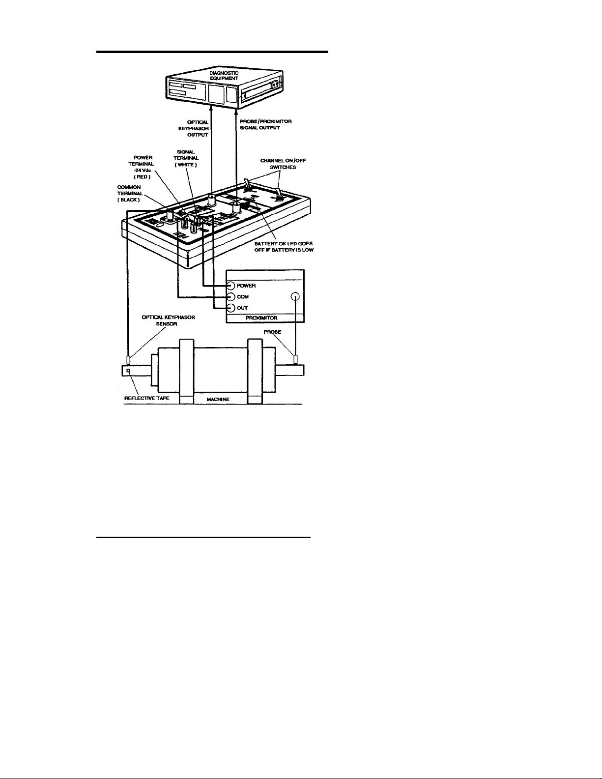
The TK84 Optical Package consists of the TK84
Temporary Transducer Interface, optical
Keyphasor®sensor, optical Keyphasor
mounting kit, cables, reflective tape, carrying
case, and manual as shown in Figure 1-1. The
TK84 Temporary Transducer Interface is a two-
channel, portable unit. Channel A is a signal
conditioner for an optical Keyphasor
transducer. Channel B is a power source for a
proximity probe transducer. Use the TK84 with
diagnostic equipment as an optical Keyphasor
trigger input or to temporarily power proximity
probe transducers during machine assembly,
probe installation, or machine balancing.
1.2 Features
• Portable (low weight, small size)
• Low cost
• Battery powered
• Optical Keyphasor and Proximitor®
power supply in one unit
• Magnetic or clamp mounting for
temporary optical pickup
1
Artisan Technology Group - Quality Instrumentation ... Guaranteed | (888) 88-SOURCE | www.artisantg.com

TK84 Temporary Transducer Interface User Guide
Figure 1-1: TK-84 Optical Package
2
Artisan Technology Group - Quality Instrumentation ... Guaranteed | (888) 88-SOURCE | www.artisantg.com

Section 1 - Introduction
Figure 1-2: TK-84 Controls and Connections
3
Artisan Technology Group - Quality Instrumentation ... Guaranteed | (888) 88-SOURCE | www.artisantg.com

TK84 Temporary Transducer Interface User Guide
1.3 Operation
WARNING
TK-84 operation can take place close to rotating
equipment. Contact with rotating equipment
can result in severe injury. Maintain safe
distance and exercise caution when using the
TK-84 near rotating equipement.
1.3.1 Powering Transducer Interfaces
The TK84 Temporary Transducer Interface
powers transducers such as Proximitor
sensors or Bently Nevada accelerometer
interface units. The output power is -24 Vdc at
12 mA minimum. This is adequate to power
one Proximitor or accelerometer interface unit.
Figure 1-2 shows the necessary connections.
Test leads and alligator clips are supplied with
the package for making these connections.
1.3.2 Optical Keyphasor®Transducer
Refer to Figure 1-3 and the steps below to
install the mounting kit.
4
Artisan Technology Group - Quality Instrumentation ... Guaranteed | (888) 88-SOURCE | www.artisantg.com

Section 1 - Introduction
Figure 1-3: Magnetic Pickup Installation
1. Clean shaft surface
2. Place reflective tape on shaft. A one-
inch squaare of reflective tape is
adequate for most shafts.
3. Install optical Keyphasor sensor in
pickup holder. Secure with lock nuts.
5
Artisan Technology Group - Quality Instrumentation ... Guaranteed | (888) 88-SOURCE | www.artisantg.com

TK84 Temporary Transducer Interface User Guide
4. Install pickup holder, with optical
Keyphasor sensor attached, in the
end of the gooseneck. Tighten pickup
holder locking knob.
5. Connect gooseneck to magnetic base,
using the threaded adapter. (An
alternate mounting method is with
the vise grip pliers. Do not use the
threaded adapter when connecting
gooseneck to vise grip pliers).
6. Mount the magnetic base (or vise grip
pliers) on the machine.
7. Loosen lever and adjust gooseneck so
pickup is about 3 inches from shaft.
Do not bend gooseneck more than 90
degrees.
8. Tighten lever to secure gooseneck.
NOTE
It may be necessary to adjust gooseneck
tension using tension adjustment. Loosen
lock nut and turn tension adjustment
clockwise (viewed from pickup end) to
tighten. Secure tension adjustment with
lock nut.
9. Connect optical sensor cable to TK84
PROBE A connector.
10. Connect TK84 OUT A to a voltmeter (to
use the TK83 Balance Master 2> connect
to the SIGNAL connector in the
DIRECT/GAP mode).
11. Set TK84 CHAN A switch to ON. Make
sure BATTERY OK light is brightly lit
and not flashing.
6
Artisan Technology Group - Quality Instrumentation ... Guaranteed | (888) 88-SOURCE | www.artisantg.com

Section 1 - Introduction
12. Rotate shaft (or move sensor) so that
sensor is pointed toward non-
reflective surface.
13. Adjust distance from shaft (1 to 4
inches) and, if required, angle to shaft
(up to 45°) until the gap voltage is +0.5
Vdc or less. See Figure 1-4.
Figure 1-4: Optical Keyphasor Signal Output Voltage
NOTE
Set the sensor at an angle to the shaft
to avoid unwanted reflections from
shiny shaft surfaces. Reflections from
the reflective tape beaded surface are
still received.
14. Rotate shaft or move sensor slightly
until it points toward the reflective
tape. The voltage reading should be
at least +5 Vdc. If not, move sensor
closer to tape until you read +5 Vdc or
greater. Then, repeat steps 12
7
Artisan Technology Group - Quality Instrumentation ... Guaranteed | (888) 88-SOURCE | www.artisantg.com

TK84 Temporary Transducer Interface User Guide
through 14 to obtain the minimum
and maximum voltages in Figure 1-4.
8
Artisan Technology Group - Quality Instrumentation ... Guaranteed | (888) 88-SOURCE | www.artisantg.com

Section 2 - In Case of Difficulty
2. In Case of Difficulty
2.1 Test and Verification
Perform the following checks to be sure the
TK84 is functioning properly.
1. Visually inspect for physical damage
to case, connectors, and switches.
2. Set CHAN A switch to ON and CHAN B
switch to OFF. BATTERY OK WHEN LIT
indicator should be brightly lit and not
flashing. If not, check battery
connection and battery condition.
3. Set CHAN B switch to ON and CHAN A
switch to OFF. BATTERY OK WHEN LIT
indicator should be brightly lit and not
flashing. If not, check battery
connection and battery condition.
4. Connect Proximitor to POWER and
COM terminals to provide load. (You
can use a 3K ± 500 ohm resistor if a
Proximitor is not available.)
5. Set CHAN B switch to ON.
6. Connect DC voltmeter between
POWER and COM terminals and
measure the voltage. It should be
from -22 to -26 Vdc.
7. Set CHAN B switch to OFF.
8. Connect optical probe cable to PROBE
A connector.
9
Artisan Technology Group - Quality Instrumentation ... Guaranteed | (888) 88-SOURCE | www.artisantg.com

TK84 Temporary Transducer Interface User Guide
9. Connect TK84 OUT A to voltmeter (you
may use a TK83 Balance Master 2.
Connect to TK83 SIGNAL connector in
the DIRECT/GAP mode).
10. Set TK84 CHAN A switch to ON.
11. Place a reflective target (white paper
or other reflective object) in front of
optical sensor. The voltmeter (or TK83)
reading should be greater than 5 Vdc
when you put the target in front of the
probe, and drop to less than 0.5 Vdc
when you remove it.
2.2 Problems
Table 2-1: Problem Symptoms and Solutions
PROBLEM CAUSE/SOLUTION
BATTERY OK WHEN LIT
off, dim, or flashing
Battery low./Replace
battery.
No output from CHAN B
OUT with Proximitor
transducer connected.
Loose or wrong
connections./Check
connections.
Erratic output from
optical Keyphasor
transducer.
Probe receiving
unwanted reflections
from shiny spots on
shaft./Readjust gap and
angle of probe to shaft.
(see Section 1.3.2,),
Reflective tape is
dirty./Replace reflective
tape.
10
Artisan Technology Group - Quality Instrumentation ... Guaranteed | (888) 88-SOURCE | www.artisantg.com

Section 2 - In Case of Difficulty
PROBLEM CAUSE/SOLUTION
Constant low output
from optical Keyphasor
transducer.
Pickup not receiving
reflection from
shaft./Readjust probe-to-
shaft gap and angle as
required
Reflective tape wrong
size or coated with
oil./Replace tape.
Pickup defective./See
Section 2.1.
Constant high voltage
output from optical
Keyphasor transducer.
Pickup receiving steady
reflection from output
from optical shiny shaft./
Adjust probe-to-shaft
gap and angle as
required.
If you require further assistance, contact
customer support using the contact
information at the front of this manual.
11
Artisan Technology Group - Quality Instrumentation ... Guaranteed | (888) 88-SOURCE | www.artisantg.com

Artisan Technology Group - Quality Instrumentation ... Guaranteed | (888) 88-SOURCE | www.artisantg.com

Section 3 - Ordering Information
3. Ordering Information
Table 3-1: TK84 Part Ordering Numbers
Component Part Number
TK84 Optical Package 82608-01
TK84 Temporary Transducer I/F 82447-01
Optical Keyphasor sensor 10798-03
Optical Keyphasor mounting kit 20211-05
Optical Keyphasor sensor holder 20197-01
Gooseneck 04490700
Vise grip pliers 20210-01
Magnetic mounting base 46000-01
Standoff adapter 49273-01
Reflective tape (15 feet) 81769-01
Battery, 9 Vdc alkaline (NEDA
1604A)
01810700
Carrying case 04160101
Manual 82594-01
Male - Male coaxial cable (6 feet) 02211505
13
Artisan Technology Group - Quality Instrumentation ... Guaranteed | (888) 88-SOURCE | www.artisantg.com

TK84 Temporary Transducer Interface User Guide
Component Part Number
Black banana lead (48 inches) 01600480
Red banana lead (48 inches) 01600482
White banana lead (48 inches) 01600489
Alligator clip 02259524
Red alligator clip boot 02259528
Black alligator clip boot 02259526
Optional Reflective tape (150 feet) 02290050
Optical Sensor extension cable 20545-xx*
*-xx is length in feet (99 feet maximum)
14
Artisan Technology Group - Quality Instrumentation ... Guaranteed | (888) 88-SOURCE | www.artisantg.com

Section 4 - Specifications
4. Specifications
4.1 General
POWER REQUIREMENTS
9 Volt transistor battery, alkaline,
5.4 Vdc to 10.0 Vdc (NEDA 1064A
or equivalent).
BATTERY LIFE
The values given below show
minimum battery life for a fresh
battery with sensors connected.
Table 4-1 shows the range of
battery life for the range of
Proximitor current drain.
Table 4-1: TK84 Battery Life in Hours
Prox
Current
(mA)
Channel A
On
(hours)
Channel B
On
(hours)
Channels A
and B On
(hours)
5 (min) 17 20 9
12 (max) 17 8 5
LOW-BATTERY CONTROL
The low-battery control circuit
disables the optical and
Proximitor power supply circuits
when the battery voltage drops
between +4.8 Vdc and + 5.4 Vdc
OPERATING TEMPERATURE RANGE
0 °C (+32 °F) to + 50 °C (+122 °F).
15
Artisan Technology Group - Quality Instrumentation ... Guaranteed | (888) 88-SOURCE | www.artisantg.com
Table of contents
Other GE Recording Equipment manuals

GE
GE WIU-2 User manual

GE
GE 4BC21A1 User manual

GE
GE Profile Series Installation manual

GE
GE Bently Nevada 86517 User manual

GE
GE Masoneilan SVI II ESD Manual

GE
GE ATS1290 User manual

GE
GE Interlogix ARITECH ATS1210 User manual

GE
GE VersaMax IC200CPUE05 User manual

GE
GE StationPortal User manual

GE
GE QuickPanel Plus IC755CxS06RDx User manual