1
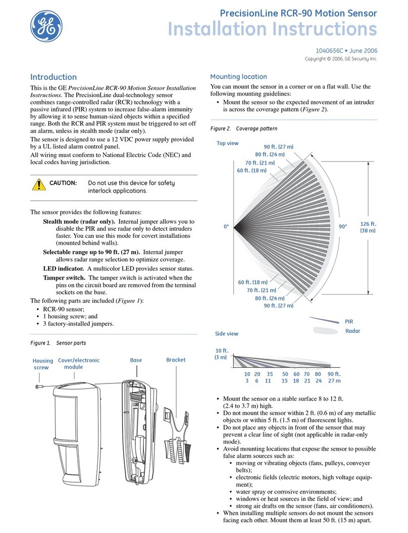
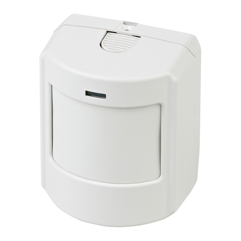
PrecisionLine RCR-50
PrecisionLineRCR-50
Dual Technology Motion Sensor
Installation Instructions
Description
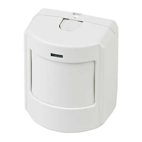
The RCR detector combines range-controlled radar (RCR)
technology with a passive infrared (PIR) system to increase
false alarm immunity by allowing it to sense human-sized
objects within a specified range. Both the RCR and PIR
systems must be triggered to set off an alarm, unless in radar-
only mode.
The detector is designed to use a 12VDC power supply
provided by a UL Listed alarm control panel.
Features
The detector provides the following features:
•High-security (radar-only) mode - Internal jumper
allows you to disable the PIR, and use the radar-only
mode to detect intruders faster. This mode can be used for
covert installations (mounted behind ceiling panels or
walls).
•Selectable range up to 50 feet (15.2m) - Internal jumper
allows radar range selection to optimize coverage.
•LED indicator - Amulti-color LED provides detector
status.
•Tamper switch - Activated when the pins on the circuit
board are removed from the terminal sockets on the base.
Parts
The following parts are included:
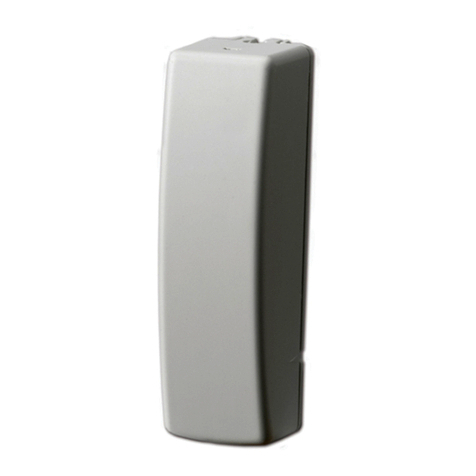
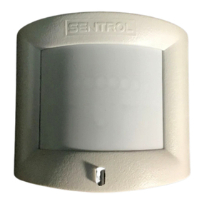
•RCR detector
•1 screw to join the case halves
•3 factory-installed jumpers
Selecting a Location for the Detector
The detector can be mounted in a corner or on a flat wall.
Use the following guidelines to determine the best location to
install the detector:
•Mount the detector so the expected movement of an
intruder is across the detection pattern. See Figure 1.
•Mount the detector on a stable surface 7 to 9 feet (2.1 to
2.7m) high.
•DO NOT mount the detector within 2 feet (0.6m) of
metallic objects or within 5 feet (1.5m) of florescent lights.
•DO NOT place objects in front of the detector that may
prevent a clear line of sight. (Not applicable in radar-only
mode.)
•Avoid locations that expose the detector to possible false
alarm sources such as:
– Moving or vibrating objects (fans, pulleys, conveyor belts)
– Electronic fields (electric motors, high voltage equipment)
– Water spray or corrosive environments
– Heat sources in the field of view (heaters, radiators)
– Windows in the field of view
– Strong air drafts on the detector (fans, air conditioners)
•When installing multiple detectors:
– DO NOT mount detectors facing each other.
– Mount detectors at least 20 feet (6.1m) apart.
– Use shorter range settings to avoid overlapping radar
coverage.
– Mounting detectors back to back is not recommended, but
if an application requires such mounting, use the 20-foot
(6.1m) range and walk test the installation to ensure proper
operation.
SPR TMPR TMPR NO COM
Figure 2. Detector (Exploded)
RadarViewingArea
PIRViewingArea
Figure 1. Coverage Patterns
90°
TopView
SideView
50’
(15.2m)
40’
(12.2m)
30’
(9.1m)
20’
(6.1m)
floorline
0’
50’
(15.2m)
40’
(12.2m)
30’
(9.1m)
20’
(6.1m)
60°30°15°
4°
0°
7’
2.1m
