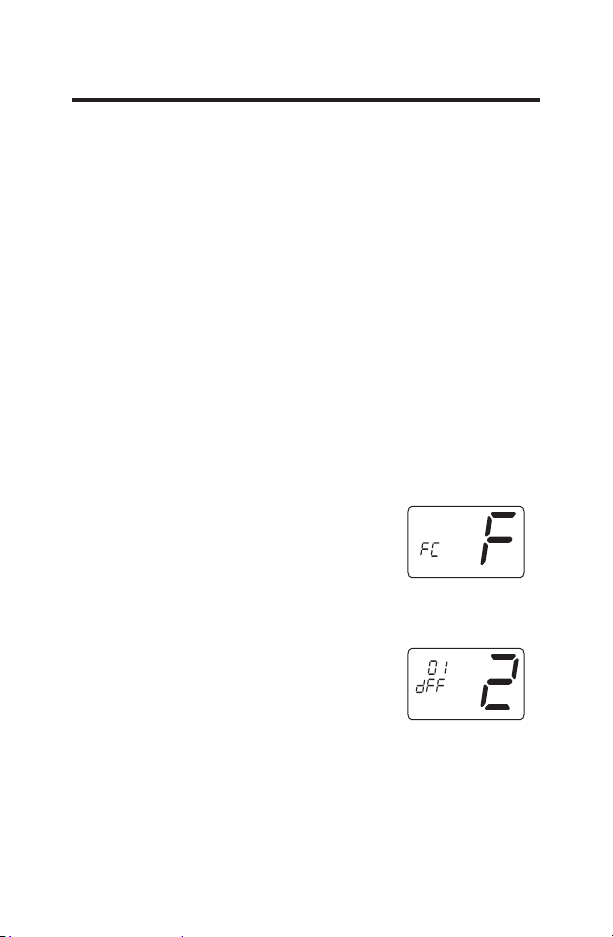
7HPSHUDWXUH'LIIHUHQWLDO³6WDJH³
5$.3RQO\²)²&³Set the
number of degrees between when stage
1 turns on and stage 2 turns on.
Press the
<
or
>
button to set differential value.
Press the Hold button to advance to the next screen.
Note: Default factory setting is 2°F/1°C for each stage.
4. Minimum Cool Setpoint (60, 64, 66, 68, 70, 72, 74, 76°F) (15,
17, 19, 20, 21, 22, 23, 24°C)
Adjust to control the minimum Cool set
temperature allowed.
Press the
<
or
>
button to select.
Press the Hold button to advance to the next screen.
Note: Default factory setting is 60°F/15°C.
5. Maximum Heat Setpoint (65, 70, 72, 74, 76, 78, 80, 85°F) (18,
21, 22, 23, 24, 26, 27, 29°C)
Adjust to control the maximum Heat set
temperature allowed.
Press the
<
or
>
button to select.
Press the Hold button to advance to the
next screen.
Note: Default factory setting is 85°F/29°C.
6. Room temperature offset (+9°F
to –9°F) (+5°C to –5°C)
Adjust to calibrate displayed room
temperature to match actual room
temperature.
Press the
<
or
>
button to select.
Press the Hold button to advance to the next screen.
Note: Move the Function switch to Heat or Cool position to
lock the settings into memory.
Note: Default factory setting is 0°F/0°C.
9
: