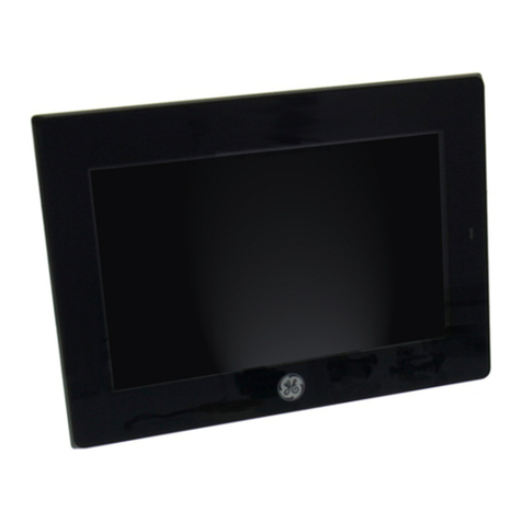
GE IC754VGB06MTD Installation manual

GE
Intelligent Platforms
Operator Interface Products
6" QuickPanel* View
Basic, Monochrome, Thin Bezel
IC754VGB06MTD
IC754VGB06MTD
Hardware User's Guide, GFK-2328B
September 2010

GFL-002
Warnings, Cautions, and Notes
as Used in this Publication
Warning
Warning notices are used in this publication to emphasize that hazardous voltages,
currents, temperatures, or other conditions that could cause personal injury exist in this
equipment or may be associated with its use.
In situations where inattention could cause either personal injury or damage to
equipment, a Warning notice is used.
Caution
Caution notices are used where equipment might be damaged if care is not taken.
Note: Notes merely call attention to information that is especially significant to
understanding and operating the equipment.
This document is based on information available at the time of its publication. While efforts
have been made to be accurate, the information contained herein does not purport to cover
all details or variations in hardware or software, nor to provide for every possible contingency
in connection with installation, operation, or maintenance. Features may be described herein
which are not present in all hardware and software systems. GE Intelligent Platforms
assumes no obligation of notice to holders of this document with respect to changes
subsequently made.
GE Intelligent Platforms makes no representation or warranty, expressed, implied, or statutory
with respect to, and assumes no responsibility for the accuracy, completeness, sufficiency, or
usefulness of the information contained herein. No warranties of merchantability or fitness
for purpose shall apply.
* indicates a trademark of GE Intelligent Platforms, Inc. and/or its affiliates. All other
trademarks are the property of their respective owners.
©Copyright 2010 GE Intelligent Platforms, Inc.
All Rights Reserved

Contact Information
If you purchased this product through an Authorized Channel Partner, please contact the
seller directly.
General Contact Information
Online technical support and GlobalCare 0H1Hhttp://www.ge-ip.com/support
Additional information 2Hhttp://www.ge-ip.com/
Technical Support
If you have technical problems that cannot be resolved with the information in this guide,
please contact us by telephone or email, or on the web at 4Hwww.ge-ip.com/support
Americas
Online Technical Support 5H6Hwww.ge-ip.com/support
Phone 1-800-433-2682
International Americas Direct Dial 1-780-420-2010 (if toll free 800 option is unavailable)
Primary language of support English
Europe, the Middle East, and Africa
Online Technical Support 11H12Hwww.ge-ip.com/support
Phone +800-1-433-2682
EMEA Direct Dial +352-26-722-780 (if toll free 800 option is unavailable or if
dialing from a mobile telephone)
Primary languages of support English, French, German, Italian, Czech, Spanish
Asia Pacific
Online Technical Support 17H18Hwww.ge-ip.com/support
+86-400-820-8208Phone +86-21-3217-4826 (India, Indonesia, and Pakistan)
19H20H[email protected] (China)
21H22H[email protected] (Japan)
Technical Support Email
23H24H[email protected] (remaining Asia customers)
25H26H[email protected]Customer Care Email
27H[email protected] (China)


Notices
GE Intelligent Platforms reserves the right to make improvements to the products described in
this publication at any time and without notice.
QuickPanel and QuickPanel View are trademarks of GE Intelligent Platforms in the United
States and other countries. Any other trademarks referenced herein are the property of their
respective owners and used solely for purposes of identifying compatibility with the products
of GE Intelligent Platforms.
The 6” QuickPanel View has been tested and found to meet or exceed the requirements of U.S.
(47 CFR 15), Canadian (ICES-003), Australian (AS/NZS 3548) and European (EN55022)
regulations for Class A digital devices when installed in accordance with guidelines noted in
this manual.
Microsoft® requires the following notes be published according to their additional
licensing provisions:
Users are advised that a maximum of ten (10) computers or other electronic devices
may simultaneously connect to, access and use services of the Microsoft Windows®
CE Operating system on the QuickPanel View solely for remote access (including
connection sharing) The ten connection maximum includes any indirect connections
made through ‘multiplexing’, or other software or hardware which pools or
aggregates connections.
Note that the QuickPanel View does not provide any server functionality utilizing
Remote Desktop Protocol (RDP) to remotely connected client computers or devices.
However, it does support connectivity to a remote Microsoft® Terminal Services
server. The server providing these services must meet these restrictions and other
Microsoft licensing requirements as applicable.
Notice Regarding Video Standards
This product is licensed under one or more video patent portfolio licenses such as
and without limitation VC-1 and MPEG4 Part 2 Visual for the personal and non-
commercial use of a consumer to:
(i) Encode video in compliance with the standards licensed under such patent
portfolio licenses and/or
(ii) Decode video that was encoded by a consumer engaged in a personal and non-
commercial activity and/or was obtained from a video provider licensed to provide
video under such patent portfolio licenses.
Such license extends to this product only and only to the extent of other notices
which may be included in this document. The license does not extend to any other
product regardless of whether such product is included with this licensed product in a
single article. No license is granted or shall be implied for any other use. Additional
information may be obtained from MPEG LA, L.L.C. See http://www.mpegla.com.

Notices
The FCC requires the following note to be published according to FCC guidelines:
This equipment has been tested and found to comply with the limits for a Class A
digital device, pursuant to Part 15 of the FCC Rules. These limits are designed to
provide reasonable protection against harmful interference when the equipment is
operated in a commercial environment. This equipment generates, uses, and can
radiate radio frequency energy and, if not installed and used in accordance with the
instruction manual, may cause harmful interference to radio communications.
Operation of this equipment in a residential area is likely to cause harmful
interference in which case the user will be required to correct the interference at his
own expense.
Any changes or modifications to the product or installation that are not expressly
approved by GE Intelligent Platforms could void the user's authority to operate the
equipment under FCC rules.
Industry Canada requires the following note to be published:
This Class A digital apparatus complies with Canadian ICES-003.
The following statements are required to appear for Class I Division/Zone 2
Hazardous Locations.
WARNING – EXPLOSION HAZARD – SUBSTITUTION OF COMPONENTS MAY IMPAIR
SUITABILITY FOR CLASS 1, DIVISION 2.
WARNING - EXPLOSION HAZARD - WHEN IN HAZARDOUS LOCATIONS, TURN OFF
POWER BEFORE REPLACING OR WIRING MODULES.
WARNING - EXPLOSION HAZARD - DO NOT CONNECT OR DISCONNECT EQUIPMENT
UNLESS POWER HAS BEEN SWITCHED OFF OR THE AREA IS KNOWN TO BE NON-
HAZARDOUS.
Power, input and output (I/O) wiring must be in accordance with Class I, Division 2
wiring methods, Article 501 10(b) of the National Electric Code, NFPA 70 and in
accordance with the authority having jurisdiction.
Users must supply an isolated DC supply to power the QuickPanel models covered by this
manual. The power supply to the QuickPanel must be limited by a slow blow fuse not to
exceed a maximum 100VA. For less than 20Vdc input, the fuse must be rated for no more
than 5A.
For a complete list of agency approvals, please refer to Appendix A.

Contents
GFK-2328B vii
Welcome.................................................................................................1-1
Getting Started........................................................................................... 1-2
Panel Cutouts............................................................................................... 1-6
To Mount the QuickPanel View in a Panel ................................................ 1-11
Overview.................................................................................................2-1
QuickPanel View Hardware......................................................................... 2-2
QuickPanel View Software........................................................................... 2-5
Detailed Operation.................................................................................3-1
Touch Screen Display.................................................................................. 3-2
Serial Communication Port........................................................................ 3-15
Ethernet...................................................................................................... 3-23
DIP Switches.............................................................................................. 3-28
Memory...................................................................................................... 3-30
Other Subsystems ..................................................................................... 3-33
Specifications ....................................................................................... A-1
Physical........................................................................................................A-1
DC Power.....................................................................................................A-2
Display .........................................................................................................A-3
Front Panel...................................................................................................A-3
Touch Screen...............................................................................................A-4
CPU..............................................................................................................A-4
Memory........................................................................................................A-4
Communication Ports...................................................................................A-4
Environmental..............................................................................................A-5
Battery..........................................................................................................A-5
Calendar/Clock.............................................................................................A-5
Agency Qualifications ..................................................................................A-6
Diagnostics ........................................................................................... B-1
Power up......................................................................................................B-1
Physical Unit ................................................................................................B-1


GFK-2327B 1-1
Welcome
Congratulations on your purchase of a QuickPanel View. The QuickPanel View
is available in different configurations to suit your requirements, either as a full-
featured HMI, or as a combination of HMI and controller for local and distributed
control applications. Equally adept in a networked environment or as a stand-
alone unit, the QuickPanel View is the ideal solution for factory floor HMI and
control.
Powered by Microsoft Windows CE.NETTM, today’s embedded operating
system of choice, the QuickPanel View provides a fast track for application
program development. The commonality with other versions of Windows
simplifies porting your existing program code. Another benefit of Windows CE is
the familiarity of the user interface, shortening the learning curve for operators
and developers alike. The availability of third-party application software makes
this operating system even more attractive.
The 6" QuickPanel View is an all-in-one microcomputer designed for maximum
flexibility. The design, based on an advanced Intel® microprocessor, brings
together a high-resolution operator interface with a variety of I/O options. With
many standard ports and expansion busses from which to choose, you can
connect to most industrial equipment.
The QuickPanel View is equipped with several memory types to satisfy even
the most demanding applications. A 16 MB section of DRAM is split between
the operating system, an object store, and application memory. A 16 MB
section of non-volatile FLASH memory, functioning as a virtual hard drive, is
divided between the operating system and persistent storage for application
programs. The many features of the QuickPanel View make it an obvious
choice for a world of applications. Your smart choice will provide reliable
operation for years to come.
Chapter
1

1-2 6" QuickPanel* ViewBasic, Monochrome, Round Bezel – September 2010 GFK-2327B
1
Getting Started
Basic Setup
Your 6" QuickPanel View is shipped ready for use after a few configuration
steps. To power up all you need to do is connect a DC power supply via the
supplied quick-connect plug. Depending on your application, you may also want
to connect and configure communications ports, as described in chapter 3.
Optional Ethernet Connection
Power Supply
Caution
Electrical Shock Hazard: To avoid personal injury or damage
to equipment, ensure that the DC supply is disconnected
from power and that the leads are not energized before
attaching them to the unit's power supply plug.

GFK-2327B Chapter 1 Welcome 1-3
1
To Connect a DC Power Supply
1. Using the three screw terminals shown in the following diagram, attach
a 24VDC, 24W power supply to the plug supplied with the QuickPanel
View. See “DC Power” in appendix A for power supply and conductor
specifications.
2. Insert the plug into the power supply socket and securely tighten the
attaching screws.
Note: The torque range for the attaching screws is 4-6 inch/lbs.
Unit Runtime Setup
To download an application to a QuickPanel View unit, you must set up a data
link between it and your development workstation. For more information, see
“Ethernet” in chapter 3 and “Downloading a Machine Edition Project” in the
Machine Edition online help.

1-4 6" QuickPanel* ViewBasic, Monochrome, Round Bezel – September 2010 GFK-2327B
1
Startup
When you first start up the QuickPanel View, a few configuration steps are
necessary.
To start the QuickPanel View
1. Apply AC power to the 24VDC supply.
Once power is applied, the QuickPanel View begins initializing. The first
thing to appear on the display is the splash screen.
2. To skip running any programs included in the StartUp folder, tap Don’t
run StartUp programs.
The splash screen disappears automatically after about 5 seconds. The
Windows CE desktop then becomes visible.
3. Tap Start, point to Settings and then tap Control Panel.
4. In the Control Panel, double-tap Display to configure the LCD
display.
5. In the Control Panel, double-tap Stylus to configure the touch screen.
6. In the Control Panel, double-tap Date and Time to configure the
system clock.

GFK-2327B Chapter 1 Welcome 1-5
1
7. In the Control Panel, double-tap System to configure a network
machine name. Many applications, including Proficy Historian require a
unique machine name. It is recommended procedure to set a unique
network name for the QuickPanel View to avoid future conflicts.
8. In the Control Panel, double-tap Network and Dial-up Connections to
configure network settings.
9. To save the settings, run Backup to save any new settings through a
power cycle.
Shutdown
There are no specific dangers associated with a power failure or other
unplanned shutdown of the QuickPanel View. In general, programs are retained
in FLASH memory and user data can be retained in battery-backed SRAM.
Some operating system settings are retained only with user intervention. We
recommend the following procedure to shut down the QuickPanel.
To shut down the QuickPanel View
1. Quit any programs that are running and wait for all file operations to
complete.
2. To save changes to operating system settings (e.g., brightness, touch
screen sensitivity) run Backup.
3. Run Reboot, as described in chapter 2. When the Windows CE desktop
reappears, remove AC power from the 24VDC supply.

1-6 6" QuickPanel* ViewBasic, Monochrome, Round Bezel – September 2010 GFK-2327B
1
Panel Cutouts
For convenience and versatility, this version of the QuickPanel View can be
mounted in cutouts of two different specifications. Refer to the appropriate
section that follows.
Small Cutout Dimensions
Depth 2.026” (51.5mm)
The unit will not fit through the small cutout with any cables connected, or with
the power supply plug inserted in the socket.

GFK-2327B Chapter 1 Welcome 1-7
1
To secure the QuickPanel View to a panel with the small cutout, use the four
included mounting clips, which hook into the openings located on the top and
bottom of the housing as shown in the following illustration.
To mount the unit in a panel with small cutout dimensions
1. Separate the small cutout gasket from the supplied gasket sheet (the
small cutout gasket is nested within the larger one, and has two
notches on each long side). Avoiding damage to the gasket, carefully
remove the covering over its adhesive backing, and then apply the
gasket with its adhesive surface toward the inner gasket channel (see
the illustration above).
2. Verify that the gasket is properly seated in the gasket channel, then
insert the unit into the panel cutout.
3. Insert the hook of each mounting bracket in the housing openings.
4. Tighten the screws to 2.6–4.4 inch/lbs (0.3–0.5 Nm).

1-8 6" QuickPanel* ViewBasic, Monochrome, Round Bezel – September 2010 GFK-2327B
1
Large Cutout Dimensions
Depth 2.594” (65.9mm)

GFK-2327B Chapter 1 Welcome 1-9
1
To secure the QuickPanel View to a panel with the large cutout, use the four
included mounting clips, which hook into the openings located on the top and
bottom of the housing, as well as the four included clip extensions, which slide
over the inner portion of the bezel as shown in the following illustration.
To mount the unit in a panel with large cutout dimensions
1. Separate the large cutout gasket from the supplied gasket sheet (the
large cutout gasket surrounds the outside of the sheet). Avoiding
damage to the gasket, carefully remove the covering over its adhesive
backing, and then apply the gasket with its adhesive surface toward the
outer gasket channel (see the illustration above).
2. Verify that the gasket is properly seated in the gasket channel, then
insert the unit into the panel cutout.
3. Slide the clip extensions over the inner portion of the bezel, at the
location of the mounting clip holes in the housing.
4. Insert the hook of each mounting clip in the housing openings.
5. Tighten the screws to 2.6–4.4 inch/lbs (0.3–0.5 Nm).

1-10 6" QuickPanel* ViewBasic, Monochrome, Round Bezel – September 2010 GFK-2327B
1
Notes:
For compliance to NEMA 4, 4x, and 12 qualification, the unit must be
mounted in a comparably NEMA rated (IP56 equivalent) panel or
enclosure.
For compliance to ATEX agency qualification, the unit must be mounted in
an IP66 panel or enclosure.
To avoid gasket degradation, limit repeated insertions or removals of the
unit and retightening of the mounting clips. For full protection, always use a
fresh gasket. Replacement gaskets may be ordered using part number
IC754ACC06GASE.
For adequate ventilation, allow at least 3 inches of space between adjacent
equipment and all sides of the QuickPanel. Ensure that specified conditions
of temperature and humidity are not exceeded.
In outdoor applications, direct sun exposure may impose increased thermal
loads on the QuickPanel leading to excessive temperature rises. Cabinet
design and orientation must be carefully considered to avoid exceeding the
operational temperature limits. These considerations could include shading
for the QuickPanel and its cabinet with awnings or other solar opaque
materials, avoiding a due East or West facing of the cabinet, ventilation or
active cooling of the cabinet, or other methods.

GFK-2327B Chapter 1 Welcome 1-11
1
To Mount the QuickPanel View in a Panel
1. Verify that the gasket is properly seated in the bezel channel, then insert the
unit into the panel cutout.
2. Insert the hook of each mounting bracket in the housing openings as shown
below.
3. Firmly tighten the screws.
Note: The torque range for the mounting bracket screws is 2.6-4.4 inch/lbs
(0.3–0.5 Nm).
The mounting clamps hold the unit in place by tension. No drilling is required.
Do not damage the gasket attached to the back of the QuickPanel. This gasket
prevents shock hazards and damage caused by liquids accidentally entering
the unit after installation.
Also, limit the number of times you remove and reinstall the unit. Too many
installations may cause gasket “set” and degradation of the seal.

Table of contents
Other GE Touch Panel manuals

GE
GE ATP2100 User manual

GE
GE IC754VSI06STD User manual

GE
GE IC755CxW07CD SERIES User manual

GE
GE QuickPanel+ IC754VGI06STD User manual

GE
GE Druck PACE1000 Instruction Manual

GE
GE Druck DPI 104-IS Instruction Manual

GE
GE IC754CSL12CTD User manual

GE
GE K0470 User manual

GE
GE druck dpi 104 User manual

GE
GE HiTech User manual

GE
GE Druck DPI 150 Use and care manual

GE
GE IC754VSL06CTD User manual

GE
GE IC754CSL06MTD User manual

GE
GE SIMON XT User manual

GE
GE IC754VBI12MTD User manual

GE
GE druck dpi 104 User manual

GE
GE 60-924-RF-TS User guide

GE
GE FTP 1000 - Security Concord LCD Touchpad User manual

GE
GE 17453- - Motion Sensing Utility Light 1 LED User manual

GE
GE IC754VSB06MTD Installation manual