849-80549-2
Installation Preparation
PREPARE TO INSTALL THE HOOD
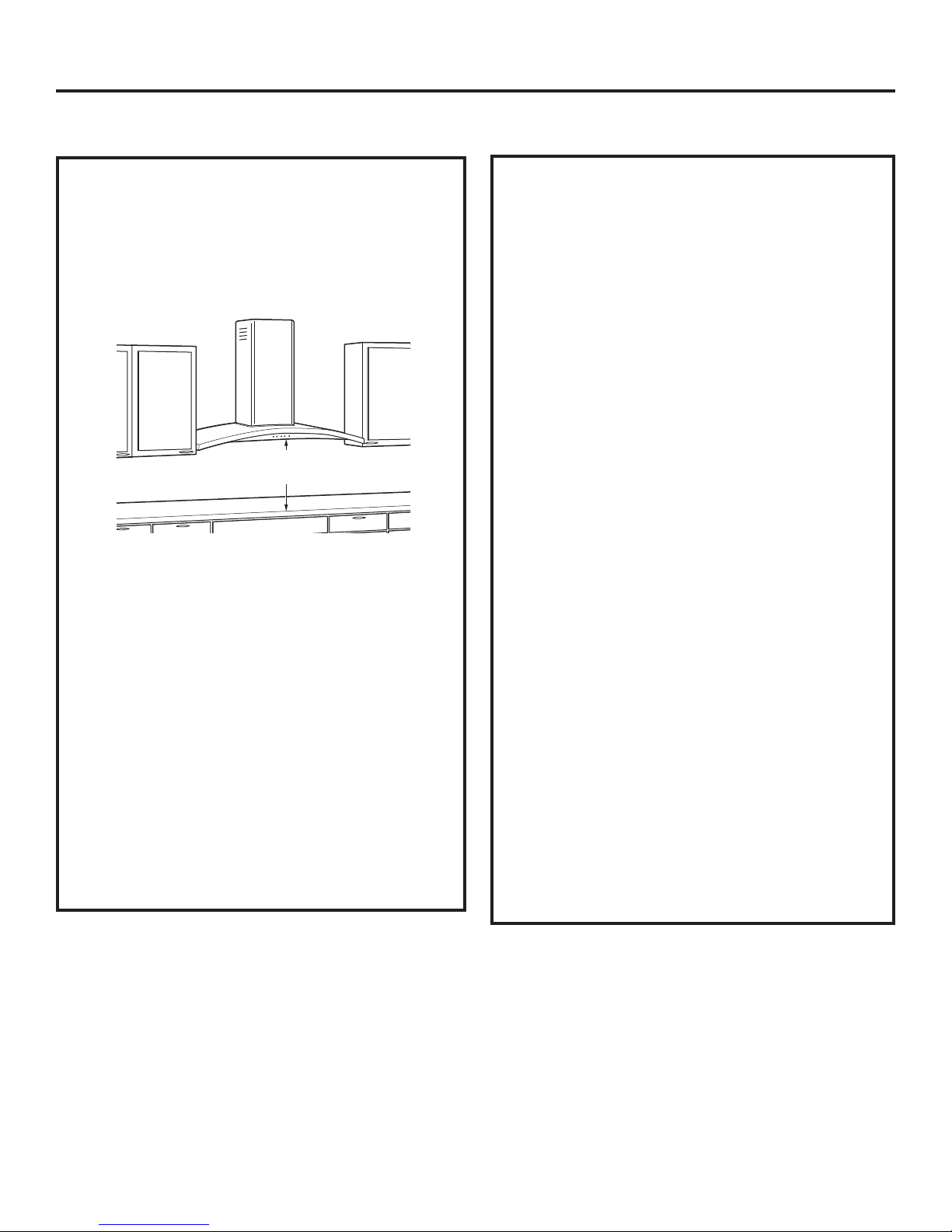
INSTALLATION CLEARANCES
These vent hoods are designed to be installed onto
a wall. They may be installed beneath a soffit or
cabinet.
,QVWDOOWKHVHKRRGVµ0LQWRµ0D[DERYHWKH
cooking surface.
The vent hood must be installed 24” min. and
µPD[DERYHWKHFRRNLQJVXUIDFH7KHKRRG
installation height above the cooking surface
depends upon ceiling height and duct cover
limitations. The telescopic duct cover conceals the
ductwork running from the top of the hood to the
ceiling. For supplied duct cover ceiling heights, see
table on page 13.
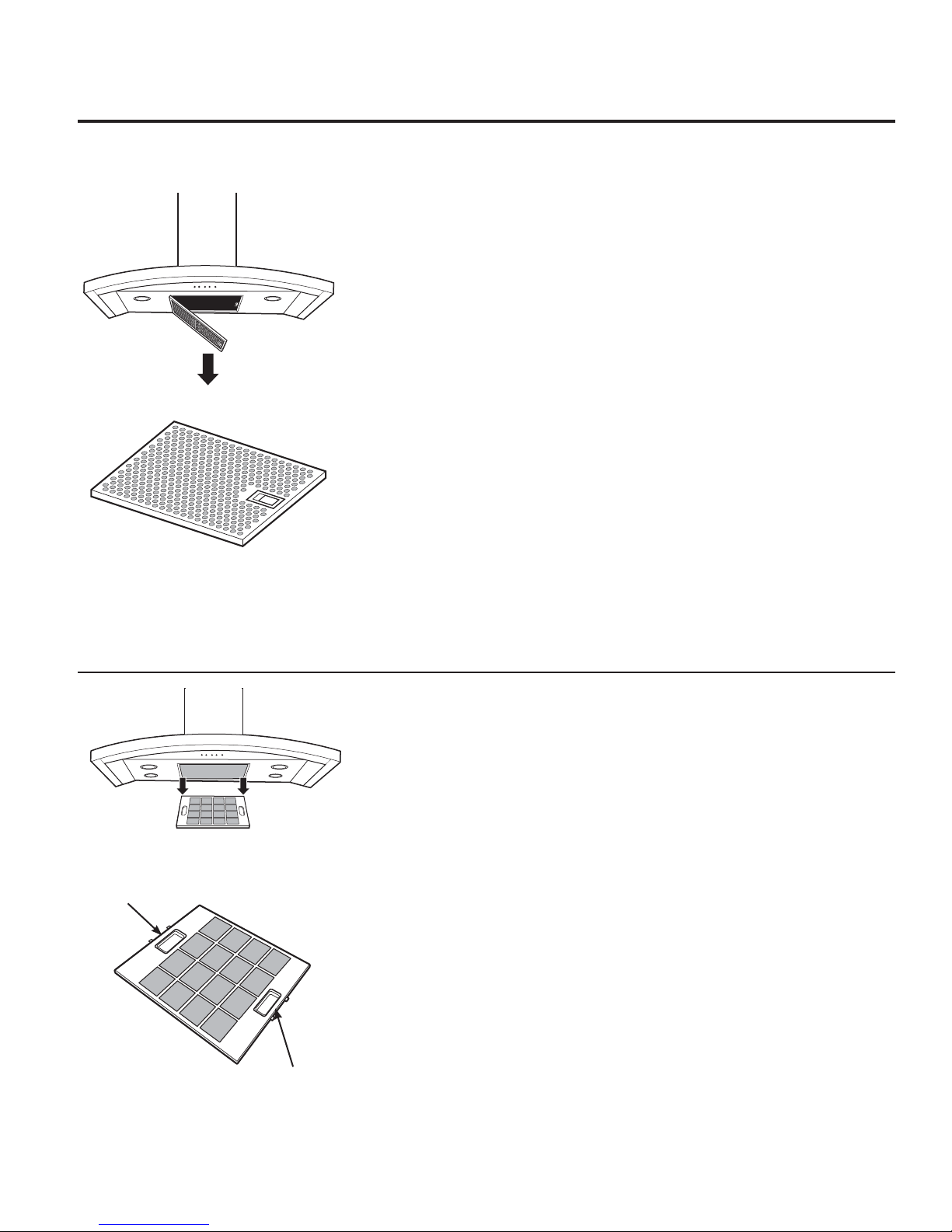
5HFLUFXODWLRQ.LW
Kit includes 1 air deflector and 1 charcoal filter and
is included with the hood.
NOTE: Installation height should be measured
from the cooking surface to the lowest part of the
hood. This hood may be installed onto a wall and
vented to the outdoors, or it can be installed for
recirculating operation. For recirculation operation,
a Recirculating Kit (included) is required.
24” Min.
µ0D[
ADVANCE PLANNING
Ductwork Planning
• This hood is designed to be vented vertically
through the ceiling. A duct transition piece is
VXSSOLHGIRUYHUWLFDOH[KDXVW8VHORFDOO\VXSSOLHG
elbows to vent horizontally through the rear wall.
See page 10.
'HWHUPLQHWKHH[DFWORFDWLRQRIWKHYHQWKRRG
• 3ODQWKHURXWHIRUYHQWLQJH[KDXVWWRWKHRXWGRRUV
• Use the shortest and straightest duct route
possible. For satisfactory performance, duct run
VKRXOGQRWH[FHHG·HTXLYDOHQWOHQJWKIRUDQ\
duct configurations.
• Refer to “Duct Fittings” chart to compute the
PD[LPXPSHUPLVVLEOHOHQJWKIRUGXFWUXQVWRWKH
outdoors.
• Use metal ductwork only.
• A transition piece for 8” round duct is supplied.
Use 8” round duct.
• Install a wall cap or roof cap with damper at
WKHH[WHULRURSHQLQJ2UGHUWKHZDOORUURRIFDS
and any transition and length of duct needed in
advance.
• When applicable, install any makeup (replacement)
air system in accordance with local building code
requirements. Visit GEAppliances.com for available
makeup air solutions.
Wall Framing for Adequate Support
• This vent hood is heavy. Adequate structural
support must be provided. The hood must be
secured to vertical studs in the wall. See page 14.
• We strongly recommend that the vent hood with
duct cover be on site before final framing and
wall finishing. This will also help to accurately
locate the ductwork and electrical service.