manuals.online logo
Brands
  1. Home
  2. •
  3. Brands
  4. •
  5. GE
  6. •
  7. Ventilation Hood
  8. •
  9. GE JV394 Training manual

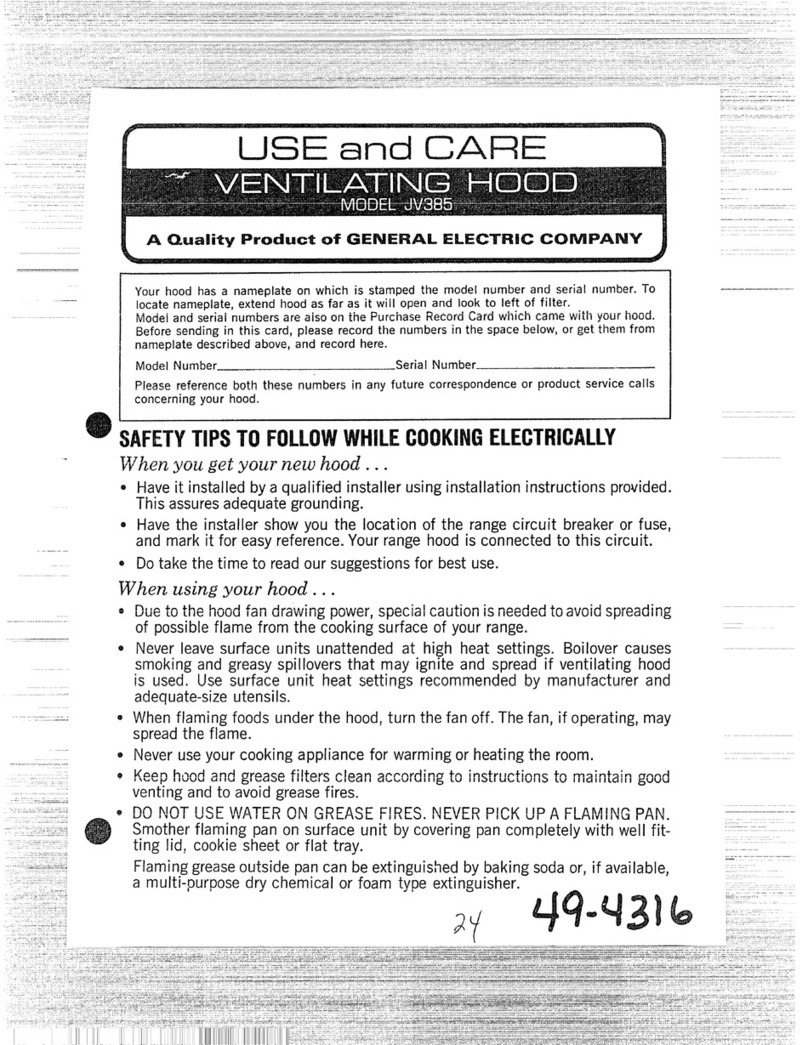
GE JV394 Training manual

Use and Care & Installation Guide I
30" VentedHood
Safety Instructions...Front Cover, 2
Operating Instructions .........2, 3
Automatic Heat Sensor ...........................3
Controls .....................................................2
Cleaning ........................... 3
Filter ............................................................3
Light Bulb Replacement ..........................3
Installation .....................................4-6
Damper/Duct Connector .........................5
Electrical Wiring .......................................6
Filter Panel .............................................3, 5
Mounting Brackets ...................................5
Consumer Support....Back Cover
Important Phone Numbers...Back Cover
Warranty ....................................................7
IMPORTANTSAFETYINFORMATION.
READALLINSTRUCTIONSBEFOREUSING.
SAFETYPRECAUTIONS
WARNING- TOREDUCETHERISKOFFIRE,
ELECTRICSHOCKORINJURY TOPERSONS,
OBSERVETHEFOLLOWING:
A. Use thi_ trait onh Ill tile nlanner intended
l)_ the n/an ufacttu el. If _ou hax e questions.
contact the nlalltlfa( ttu el.
B. Befol e set _icing ol cleaning unit. switch
powei off at _mxice panel and lock tile _elxite
distonnectJug means to p_exent l)owel fl o1/1
being _wnched on accidentally. \\'hen the
ser\ it e dJ,sconneetino nlean5 {annot be locked,
se{tuel* f;t_ten a plominent walning de\ice.
such as a tag. to the se_ice panel.
C. Do not use thi_ tlnlt with an* sohd-state speed
contJ ol dex ice.
D. [r_e _ ith appl oxed col d-( onnet tion kit onh.
E. This trait must be glounded.
WARNING- TOREDUCETHERISKOFA
RANGETOPGREASEFIRE:
A. Nexel lent e stu face unit_ unattended at high
settings. Boilox el _ cause sm_&ing and gLeas*
_pillo\ ets that in,l) ignite. Heat oih sh,_h' on
lo*x ok nledJunl settings.
B. )dwm s turn hood ON when cooking on high
heat or \_hen tlambeing food (i.e.. (Thepes
Suzette. ChelrJesJul)Jlee, PeppmtoHl Beef
Flambt: I.
C°
D.
Clean _entilating fan_ flequenth. ( ;1ease qlotdd
not be alh,*_ed to accumulate on fall (-71filtel.
[Tsei)l ()pet pan size. Alwm s use t ook\x aie
appJ opuate fm the size of the qllface
elelllent.
f_o*Hmztul *t_\t pao_ *
49-80421 I
ge.com
IModels: JV394 JV395 JV396 dV930
IMPORTANTSAFETYINFORMATION.
READALLINSTRUCTIONSBEFOREUSING.
SAFETYPRECAUtiONS
CAUTION-FORGENERALVENTILATINGUSEONLY. WARNING-- TOREDUCETHERISKOFFIRE,
DONOT USETOEXHAUSTHAZARDOUSOREXPLOSIVE ELECTRICSHOCKORINJURY TOPERSONS,OBSERVETHE
MATERIALSAND VAPORS. FOLLOWING:
WARNING- To REDUCETHERISKOFINJURY TO
PERSONSIN THEEVENTOFA RANGETOPGREASEFIRE,
OBSERVETHEFOLLOWING*."
A. SMOTHER FLAMES with a close-fitting lid.
cookie sheet or metal tray, then turn off the burner.
BE CAREFUl, TO PREVENT BURNS. If the flames
do not go out innnediately, EVACUATE AND CALL
THE FIRE DEPARTMENT.
B. NEVER PICK U P A FLAMING PAN You may
be burned.
C. DO NOT USE WATER. including wet dishcloths
oi towels--a violent steam explosion w_ll result.
D. Use an exunguisher ONLYif:
1. You know you have a Class ABC extingulshm:
and you already know how to operate it.
2. The fire is small and contained in the area
where it started.
3. The fire depamnent is being called.
4. You can fight the fire with yore" back to an exit.
* Based_on "Kitchen Firesafety Tips" published by NFPA.
A. Installation work and electrical wiring must be done by
qualified person(s) in accordance with all applical)le
codes and standards, including fire-rated consn-uction.
B, Sufficient air is needed for proper combustion and
exhausting of gases through the flue (chimney) of
fuel bm'ning equipment to prevent back drafting.
Follow the heating equipment manufacturer's
guideline and safety standards such as those
published b) the National Fire Protection Association
(NFPAL and the American Society for Heating,
Refligeration and Air Conditioning Engineers
(ASHRAEL and the local code authorities.
C. When cutting or drilling into wall or ceiling, do not
damage electrical wh'ing and other hidden utilities.
D. Ducted fans must alwm_sbe vented to the outdoors.
WARNING- TOREDUCETHERISKOFFIRE,
USEONLYMETALDUCTWORK.
• Do not attempt to repair or replace aW part of)ore"
hood unless it is spedfically recommended in this
guide. All other seiMcing should be referred to a
qualified technician.
READANDFOLLOWTHISSAFETYINFORMAtiONCAREFULLY.
READANDSAVETHESEINSTRUCTIONS
OPERATING INSTRUCTIONS
Always turn your hood on before you begin cooking to establish an air flow
in the kitchen. Let the hood run for a few minutes to clean the air after you
turn the range off. This will keep the whole kitchen cleaner.
Controls
The hood is "OFF" when the glass visor is pushed
completely in.
LIGHT-The light will turn "ON" when the glass
visor is pulled out approximately 1/2 inch.
BLOWER-The blower will turn "ON" when the
drawer is pulled out approximately 1l½inches.
The blower speed is set using the slide control,
located to the right of the drawer.
2
Automatic Heat Sensor
Your hood is equipped with an automatic thermostat.
This thermostat is a device that will turn on or speed
up the blower if it senses excessive heat above the
cooking surface.
If your blower is not on, or if it is running at low speed,
the thermostat will sense excessive cooking heat,
override the normal blower control and turn the blower
on to high speed. The blower will run until the
temperature drops lo normal operating level. The blower
will then automatically return to its original setting.
CARE AND CLEANING
WARNING: ALWAYS DISCONNECT ELECTRIC POWER SUPPLY BEFORE SERVICING HOOD.
Use a mild detergent suitable for painted surfaces.
DO NOT USE ABRASIVE CLOTH, STEEL WOOL
PADS OR SCOURING POWDERS. Vacuum the
blower to clean it. Do not immerse the blower in water.
The glass visor assembly and light lens are easily
removable for cleaning:
DO NOT clean in a dishwasher.
Remove the light lens by opening the filter panel and
turning the 2 metal clips holding the lens in place.
Filter
Slide the glass visor open.
Open the filter panel
by turning the two clips and
allowing it to swing free.
Flex the filter in the middle
to remove it. Panelclip
Wash and rinse the filter in a
mild detergent solution.
Replace the filter before using the exhaust fan.
Glass visor
Filter panel /
Grasp filter
remove
Light Bulb Replacement
This hood uses a 24" long F20T12 fluorescent
tube and an FS-2 starter, which are available at
most hm-dware stores or home centers.
To check or replace tube:
1. Pull the drawer out.
2. Rotate the filter panel clips and lower the
filter panel.
If the tube flickers or does not light, check the prongs
on the ends of the tube to make sure they are properly
seated in the tube holders.
If the tube continues to flicker or does not light,
replace the tube. Slide the tube into the holders and
rotate the tube so that the prongs in the holders grip
the tube and hold it in place.
If the ends of the tube light but the center does not,
the starter may require replacement. The starter is
located behind the filter panel on the right hand side.
Install the new starter by pushing the starter in and
turning it clockwise.
Stainless Steel (on some models)
Do not use asteel wool pad; it will scratch the
surface.
To clean the stainless steel surface, use warm sudsy
water or a stainless steel cleaner or polish. Always
wipe the surface in the direction of the grain. Follow
the cleaner instructions for cleaning the stainless steel
surface.
To inquire about purchasing stainless steel appliance
cleaner or polish, or to find the location of a dealer
nearest you, please call our toll-free number:
National Parts Center 1.800.626.2002
ge.com 3
TOOLSYOU WILL NEED
Flat blade and Phillips Pencil
screwdrivers Duct tape
Metal Snips
Saw (saber or keyhole) Electric Drill (in some applications)
Pliers Tape measure Wire stripper
Flashlight Caulking Level
PLANTHEINSTALLATION
Caution: Remove the house fuse or open the
circuit breaker before beginning the installation.
Your new hood will fit astandard 30" wide flush bottom
orrecessed bottom, framed or frameless kitchen cabinet
which has a minimum depth of 11" from the face to
the inside of the back wall.
The unit is ducted vertically. To change to horizontal
ducting see the instructions.
For safe operation, the mounted hood must be a
minimum of 24" above the cooking surface.
For easiest installation, the range hood should be installed
in the cabinet before mounting the cabinet to the wall.
NOTE: Remove the glass visor from the unit before
installing the hood in the cabinet to protect the visor
from damage.
This hood can easily be installed by following these
basic steps:
• Mark and cut out the cabinet bottom.
• Secure the hood to the cabinet.
• Mount the cabinet on the wall.
• Connect the ductwork and the rower cable.
T
24" MIN.
FLUSH BOTTOM CABINET
11 II..........
-r
24" M[N.
RECESSED BOTTOM CABINET
WORKSHEETmCALCULATETOTAL
EQUIVALEHTDUCTWORKLEHGTH
DUCI" EQUIVALENTNUMBER
PIECES LENGTH X USED TOTAL
_ 3W'x10" 1 Ft. x ( ) = Ft.
Rect.,
straight
(_ 3W'x10" 14 Ft. x ( ) = Ft.
Rect.900
elbow
3W'xl0" 8Ft. x ( ) = R.
1_ Rect.450
elbow
3Y4"x10" 33 Ft. x ( ) = Ft.
Rect.900
flatelbow
3W'x 10" 24 Ft. x ( ) = Ft.
Rect. (18ft.w/o
wallcap damper) x ( ) = R.
withdamper
Totalductwork = Ft.
MAXIMUM DULl" LENGTH: For satisfactory air
movement, the total duct length of a 31A"x 10" rectangular
duct should not exceed 65 equivalent feet.
IHSTALLTHEHOOD
1. Mark and cut out the cabinet bottom.
CABINET
1,-518"
9-1/2"
(4) 3/8" DIA.
CLEARANCE
HOLES
Prepare the cabinet bottom as shown above. Be sure
to locate the cut-out and four holes from the front of
the cabinet to assure a flush mount.
4
2. Attach the damper/duct connector.
>i
#8-18 x 3/8"
ELECTRICAL
KNOCKOUTS
FRONT
OF HOOD
Use two (2) screws (provided) to attach the connector
to the housing. The damper flap should open in the
direction indicated by the arrow.
3. Remove the electrical knockout.
Choose either the top or side of the housing for the
electrical cable entrance. Remove the appropriate
knockout.
4. Set the housing into the opening.
SLIDE
Carefully lower the housing into the cabinet opening
with the slide control to the front.
5. Remove the access cover.
T v,
I
ACCESS
COVER
6. Open the filter )and.
VISOR
SLIDES
Pull the visor slides out. Rotate the panel clips
and swing the panel open.
7. Install the mounting brackets.
Insert the bent end of the installation rod into the
access hole in the housing.
R
Choose the mounting bracket with the center hole.
Hang the bracket from the rod, through this center
hole, as shown. Pull the bracket up between the
cabinet and housing.
I
OR
#8-18 x 1"
INSERT
SCREWS
HERE
Holdthe mountingbracket inplacewiththe rod. Two
sets ofscrews are provided.Use the short screws for
flush bottomcabinetsor the long screwsfor recessed
bottomcabinets. Insert two (2) screwsthrough the
housing and into the mountingbracket.Donot tighten
the screws completely.
5

This manual suits for next models

3

Other GE Ventilation Hood manuals

GE Monogram ZVB30 User manual

GE

GE Monogram ZVB30 User manual

GE UVW7301 Original instructions

GE

GE UVW7301 Original instructions

GE Monogram ZV750 How to use

GE

GE Monogram ZV750 How to use

GE 36" CUSTOM HOOD INSERT ZVC36LSS Manual

GE

GE 36" CUSTOM HOOD INSERT ZVC36LSS Manual

GE Cafe CV936MSS Manual

GE

GE Cafe CV936MSS Manual

GE MONOGRAM ZV750SY User manual

GE

GE MONOGRAM ZV750SY User manual

GE Monogram ZV950 User manual

GE

GE Monogram ZV950 User manual

GE Monogram ZV950 User manual

GE

GE Monogram ZV950 User manual

GE Monogram ZV750 User manual

GE

GE Monogram ZV750 User manual

GE Monogram ZV42 User manual

GE

GE Monogram ZV42 User manual

GE JV535 Operating instructions

GE

GE JV535 Operating instructions

GE Monogram ZV1050 User manual

GE

GE Monogram ZV1050 User manual

GE GE Monogram ZV850SPSS Manual

GE

GE GE Monogram ZV850SPSS Manual

GE MNU720 User manual

GE

GE MNU720 User manual

GE Monogram ZV30 User manual

GE

GE Monogram ZV30 User manual

GE UVC9300 Original instructions

GE

GE UVC9300 Original instructions

GE Profile JV536HSS User guide

GE

GE Profile JV536HSS User guide

GE JV694SBB Training manual

GE

GE JV694SBB Training manual

GE Monogram ZVB30 User manual

GE

GE Monogram ZVB30 User manual

GE GE Monogram ZVC30 User manual

GE

GE GE Monogram ZVC30 User manual

GE UVW8361 Original instructions

GE

GE UVW8361 Original instructions

GE MONOGRAM ZV750SY User guide

GE

GE MONOGRAM ZV750SY User guide

GE Monogram ZV881WSS User manual

GE

GE Monogram ZV881WSS User manual

GE JV367HWW Service manual

GE

GE JV367HWW Service manual

Popular Ventilation Hood manuals by other brands

Gorenje S3 IHGC963S4X manual

Gorenje

Gorenje S3 IHGC963S4X manual

KOBE ISX2136SQB-1 Installation instructions and operation manual

KOBE

KOBE ISX2136SQB-1 Installation instructions and operation manual

U.S. Products ADVANTAGE-100H Information & operating instructions

U.S. Products

U.S. Products ADVANTAGE-100H Information & operating instructions

Kuppersberg DUDL 4 LX Technical Passport

Kuppersberg

Kuppersberg DUDL 4 LX Technical Passport

Framtid HW280 manual

Framtid

Framtid HW280 manual

Thermador HGEW 36 FS installation manual

Thermador

Thermador HGEW 36 FS installation manual

Electrolux LFT769X user manual

Electrolux

Electrolux LFT769X user manual

AEG X69453MVO UK user manual

AEG

AEG X69453MVO UK user manual

Broan B5836SS manual

Broan

Broan B5836SS manual

Heinner HDCH-6060RGBK quick start guide

Heinner

Heinner HDCH-6060RGBK quick start guide

Baumatic AS35SS instruction manual

Baumatic

Baumatic AS35SS instruction manual

Franke FTF 604 XS V2 Instructions for use and installation

Franke

Franke FTF 604 XS V2 Instructions for use and installation

Best UCB3I30SBW installation instructions

Best

Best UCB3I30SBW installation instructions

Gram EFU 503-90 X instruction manual

Gram

Gram EFU 503-90 X instruction manual

CIARRA CBCS6803 Installation and user manual

CIARRA

CIARRA CBCS6803 Installation and user manual

sauter SHG501 Instructions for installation and use

sauter

sauter SHG501 Instructions for installation and use

Franke 392-17 User instructions

Franke

Franke 392-17 User instructions

FALMEC Polar Black 35 Instruction booklet

FALMEC

FALMEC Polar Black 35 Instruction booklet

manuals.online logo
manuals.online logoBrands
  • About & Mission
  • Contact us
  • Privacy Policy
  • Terms and Conditions

Copyright 2025 Manuals.Online. All Rights Reserved.