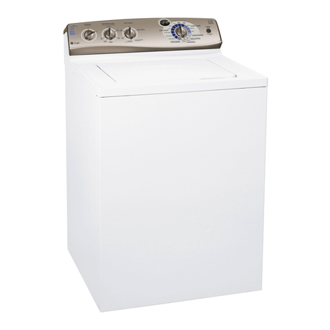
GE WSXH208T How to use


1
CONTENTS
FEATURES .................................................................................................................................................. 2
TECHNICAL SPECIFICATIONS .................................................................................................................. 3
TORQUE REQUIREMENT TABLE .............................................................................................................. 4
RESISTANCE TABLE ................................................................................................................................. 5
SCHEMATIC DIAGRAM .............................................................................................................................. 6
TIMER CYCLE CHART................................................................................................................................ 7
ELECTRONIC SPEED CONTROLLER ....................................................................................................... 8
WIRING DIAGRAM ...................................................................................................................................... 9
TROUBLESHOOTING DIAGRAMS............................................................................................................. 10
CONSTRUCTION AND OPERATION.......................................................................................................... 16
FUNCTIONAL COMPONENTS AND PARTS .............................................................................................. 21
Top Panel ..................................................................................................................................................... 21
Service Panel ............................................................................................................................................... 21
Loading Door ................................................................................................................................................ 21
Door Strike ................................................................................................................................................... 21
Door Hinge ................................................................................................................................................... 22
Door Safety Switch Assembly (Door Lock) ................................................................................................... 22
Timer ............................................................................................................................................................ 22
Timer Diagnostic Aid .................................................................................................................................... 24
Water Level Control ...................................................................................................................................... 26
Water Temperature Selector Control ............................................................................................................ 26
End of Cycle Signal ...................................................................................................................................... 27
Extra Rinse Switch ....................................................................................................................................... 27
Water Inlet Valve .......................................................................................................................................... 27
Automatic Dispenser .................................................................................................................................... 29
Drive Motor ................................................................................................................................................... 31
Drive Belt ...................................................................................................................................................... 32
Electronic Speed Control .............................................................................................................................. 33
Drain Pump and Motor Assembly ................................................................................................................. 34
Air Bell and Pressure Connecting Tube ........................................................................................................ 34
Tub Counterweights ..................................................................................................................................... 35
Air Shock Absorber....................................................................................................................................... 36
Door Bellows ................................................................................................................................................ 36
Outer Tub ..................................................................................................................................................... 36
Inner Tub and Bearings ................................................................................................................................ 37
Tub Vanes .................................................................................................................................................... 38
Exploded Views ............................................................................................................................................ 39
Timer Diagnostic Aid .................................................................................................................................... 42
Thisservicemanualis intended for use by persons having electrical and mechnical training and a level
of knowledge of these subjects generally considered acceptable in the appliance repair trade. The
manufacturer cannot be responsible, nor assume any liability, for injury or damage of any kind arising
from the use of this manual.
WARNING
RETURN MAIN MENU

2
FEATURES
PLASTIC OUTER TUB - The two piece outer tub is formed from tough, lightweight polypropylene.
STAINLESS STEEL TUB - The wash tub, which has a 25 year warranty, is constructed of durable stainless
steel .
DISPENSER DRAWER - The dispenser drawer will add diluted detergent, bleach, and fabric softener at the
correct time during the wash or rinse cycles.
SUSPENSION SPRINGS - The tub assembly is supported from the mid-section by two suspension springs
which limit vibration to the outer cabinet.
AIR SHOCKS - Two air shocks dampen tub vibration during out of balance conditions.
FRONT MOUNTED TIMER - The timer is mounted to the front control panel. The timer knob contains an
adjustment feature to calibrate the indicator mark.
MOTOR SPEED CONTROLLER LOCATION - The motor speed controller is mounted to the right rear
corner of the base where it is protected from damage.
DOOR LOCK PTC - The PTC keeps the door locked during spin and tub coast down.
REPLACEABLE SIDE PANELS - Side panels are replaceable, but are riveted to base and front panel for
additional strength and rigidity.
FIXED FRONT PANEL - The front (upper) panel is riveted to the side panels for maximum cabinet strength
and rigidity.

3
MODEL SPECIFICATIONS WSXH208T0WB
Cycles
Regular
Agitate (in seconds) 13.3
Pause (in seconds) 3.3
Delicate
Agitate (in seconds) 3.3
Pause (in seconds) 13.3
Electronic Speed Control yes
(Operational Speeds)
Wash Speed 52 RPM
Spin Speed - slow 450 RPM
Spin Speed - fast 850 RPM
Drain Pump Motor (Detached 120 VAC Motor)
Pump Out Height Maximum (inches) 96
Drain Hose Length to Pump (Inches) 60
Pump Out Time 60 sec. max.
Pump Speed - RPM 2550
Pump Output
@ 3 ft. 13.0 GPM
@ 6 ft. 10.0 GPM
@ 8 ft. 8.0 GPM
Drive Motor (16 Pole Universal DC Motor)
Drive Belt (Poly-V, 6 rib) yes
Pulley Ratio (Pulley to Motor RPM) 1 to 16
Water Supply
Water Pressure - Maximum (PSI) 120
Water Pressure - Minimum (PSI) 15
Total Water Usage (max. gallons approx.) 25
Water Level (no load - measured from bottom of spin drum) 4-5/8" ± 3/8"
Electrical Data
Drive Motor (16 Pole DC Type Motor)
Volts (120, 60 Hz.) 15 amp yes
Wash R.P.M. 832
Spin R.P.M. 10400
Wattage
Agitate (with 10 pound clothes load) 370 max.
Spin (with 10 pound clothes load) 850 max.
Plumbing Requirements
Drain 1-1/2" Standpipe (minimum height 24") yes
Water Supply - Separate Hot & Cold Faucets yes
(3/4", 11-1/2 threads per inch)
Capacity (Inner Tub)
Cubic feet 2.65
Max clothes load 14 lbs.
Dimensions (Inches Minimum)
Height 34-5/8
Width 26-7/8
Depth 27 1/4
TECHNICAL SPECIFICATIONS

4
TORQUE REQUIREMENT TABLE
DESCRIPTION TORQUE
Buzzer Mounting 25 - 35 in. lbs.
Counterweight to Tub 60 - 75 in. lbs.
Door Hinge to Cabinet 30 - 45 in. lbs.
Door Hinge to Door 25 - 35 in. lbs.
Door Latch 10 - 15 in. lbs.
Door Lock Switch 15 - 25 in. lbs.
Door Frame Assembly
Screws 10 - 15 in. lbs.
Drain Pump to Pump
Bracket 25 - 35 in. lbs.
Tub Support to Tub 24 ft. lbs.
Extra Rinse Switch 24 - 35 in. lbs.
Motor to Tub 25 - 35 in. lbs.
Outer Tub Halves (front to
rear) 70 - 85 in. lbs.
Pressure Switch
Mounting 15 - 20 in. lbs.
Tub Pulley to Shaft 310 - 350 in. lbs.
Timer Mounting 20 - 40 in. lbs.
Water Temperature
Switch 15 - 20 in. lbs.
Water Valve Mounting 25 - 35 in. lbs.

5
RESISTANCE TABLE
RESISTANCE TABLE
Resistance Ohm value +10% @ 770F (250C)
Door Lock Solenoid 380
Drive Motor
Stator Winding
(Tapped Field)
Stator Winding (Full
Field)
Tachogenerator
Motor Thermal
Protector
Armature (Rotor)
0.37
1.26
135
less than 1
less than 5
Pump Motor 4.6
Timer Motor 2070
Water Valve
Solenoids 880

6
SCHEMATIC DIAGRAM

7
TIMER CYCLE CHART

8
ELECTRONIC SPEED CONTROLLER
MOTOR MOVEMENT
1 Sec.Max.
1 Sec.
Max.
1 Sec.
Max. 1 Sec.
Max.
1 Sec.
Max.
1 Sec
Max.
1 Sec
Max.
42 42
20 ± 1 27.00 26.67
90 90
450 450
650
450
0
0 0
0 0
52
3.3 Sec
t (sec)
t (sec)
t (sec)
t (sec)
DRUM RPM
DRUM RPM
- NORMAL (N) WASH PHASE
- SPIN 1 (S1) PHASE
- DELICATE (D) WASH PHASE
- INTERVAL SPIN (S1+ S1) PHASE
- SPIN 2 (S2) PHASE
DRUM RPM
DRUM RPM
DRUM RPM
37.00
52
t (sec)
SPEED CONTROL
OPERATION
CONNECTOR NUMBER C1 .2 C1 . 3 C1 . 5 C1 . 6
SPEED CONTROL CODE E D B A
TIMER CONTACT 4 B 24 B 9 B 9 A
DRUM
RPM TUB OPERATION MOTOR MOVEMENT (See
Below)
52 AGITATE - CONTINUOUS (NORMAL) N 0 1 0 1
52 AGITATE - DELICATE (& DRAIN) CYCLE D 0 1 1 0
450 SPIN - CONTINUOUS S1 1 X 0 0
450 INTERVAL SPIN S1+S1 1 X 0 1
650 SPIN - CONTINUOUS S2 1 X 1 0
1 = 120 VAC, 0 = 0 VAC, X = DON’T CARE
850
850

9
WIRING DIAGRAM

10
STRIP CIRCUIT TROUBLESHOOTING
NOTE: DASHEDLINES INDICATE INTERNAL TIMER JUMPER WIRES.
TIMER
LINE SWITCH
TIMER
LINE SWITCH
TIMER
LINE SWITCH
TIMER
LINE SWITCH
DOOR
LOCK SWITCH
DOOR
LOCK SWITCH
DOOR
LOCK SWITCH
TIMER
TIMER
TIMER
WATER
TEMP SWITCH
WATER
TEMP SWITCH
TIMER
TIMER
WATER
TEMP SWITCH
WATER
TEMP SWITCH
TIMER
TIMER
DISPENSER DRAWER
MAGNETIC REED SWITCH DOOR LOCK
SOLENOID
HOT WATER
SOLENOID
HOT
WATER
SOLENOID
COLD WATER
SOLENOID
COLD WATER
SOLENOID
BLK
BLK
BLK
BLK
BLK BLU/WHT WHT
BLU/WHT WHT
BLK/RED
BLK/RED
BLK/RED
TAN/BLK
TAN/BLK
TAN/BLK
PURP
PURP
ORG
ORG
WHT
WHT
WHT
WHT
YEL
YEL
DK BLUE
WHT
WHT
DK BLUE
BLK
BLK
BLK
DOOR LAMP WON’T LIGHT OR
DOOR LOCK SOLENOID WON’T ENERGIZE
DOOR LAMP WON’T LIGHT OR
DOOR LOCK SOLENOID WON’T ENERGIZE
IF NO HOT WATER DURING WASH FILLIF NO HOT WATER DURING WASH FILL
IF NO WARM WATER DURING WASH FILLIF NO WARM WATER DURING WASH FILL
IF NO COLD WATER DURING WASH FILLIF NO COLD WATER DURING WASH FILL
L1 N
1A
1A
1A
1A
COM
COM
COM
6
6
6
2
2
8
8
5
5
2
DOOR LAMP
21
WATER LEVEL
CONTROL
WATER LEVEL
CONTROL
WATER LEVEL
CONTROL
2
2
2
3
3
3
1
1
1
1
1
1
1
NO
NO
NO
6A
6A
6A
4
4
8B
8B
1
1
6B
COLD
WATER
SOLENOID
COLD
WATER
SOLENOID
6B
1
3
3
3
3

11
NOTE: DASHEDLINES INDICATE INTERNAL TIMER JUMPER WIRES.
TIMER
LINE SWITCH
TIMER
LINE SWITCH
TIMER
LINE SWITCH
TIMER
LINE SWITCH
TIMER
LINE SWITCH
TIMER
LINE SWITCH
TIMER
LINE SWITCH
DOOR
LOCK SWITCH
DOOR
LOCK SWITCH
DOOR
LOCK SWITCH
DOOR
LOCK SWITCH
DOOR
LOCK SWITCH
DOOR
LOCK SWITCH
DOOR
LOCK SWITCH
TIMER
TIMER
TIMER
TIMER
WATER
TEMP SWITCH TIMER WATER
TEMP SWITCH
TIMER
TIMER
TIMER
TIMER
TIMER
MOTOR
PUMP
MOTOR
TIMER
MOTOR
TIMER
TIMER
COLD WATER
SOLENOID
CYCLESIGNAL
BUZZER
DOOR LOCK
PTC
COLD WATER
SOLENOID
HOT
WATER
SOLENOID
BLK
BLK
BLK
BLK
BLK
BLK
BLK
BLK/RED
BLK/RED
BLK/RED
BLK/RED
BLK/RED
BLK/RED
BLK/RED
TAN/BLK
TAN/BLK
TAN/BLK
LT BLUE
TAN/BLK
BLK/RED
BLK/RED
LT
BLUE PURP YEL
WHT
WHT
WHT
WHT
WHT
WHT
WHT
WHT
PINK
WHT
DK BLUE
GRAY
RED
WHT
DK BLUE
DK
BLUE
BLK
BLK
BLK
BLK
BLK
BLK
BLK
L1 N
1A
1A
1A
1A
1A
1A
1A
COM
COM
COM
COM
COM
COM
COM
6
6
TIMER
6
TIMER
7
TIMER
7
TIMER
9
TIMER
9
TIMER
24B
TIMER
24B
TIMER
5
TIMER
6
4
4
18A 2
5A
7
5A
WATER LEVEL
CONTROL
WATER LEVEL
CONTROL
WATER LEVEL
CONTROL
WATER LEVEL
CONTROL
WATER LEVEL
CONTROL
WATER LEVEL
CONTROL
WATER LEVEL
CONTROL
2
2
2
2
2
3
3
3
3
3
1
1
1
1
1
1
1
1
1
1
1
1
1
1
NO
NO
NO
NO
NO
NO
NO
6B
6B
4A
4B
14A
TIMER 14B
TIMER
COLD
WATER
SOLENOID
38 46A
5
7B
5
14B
14B
3
3
3
3
3
3
3
MS
M
MS
IF NO WARM WATER DURING RINSE FILL
IF NO COLD WATER DURING RINSE FILL
IF NO END-OF-CYCLE SIGNAL (BUZZER)
IF DOOR LOCK OPENS DURING SPIN
IF TIMER WON'T ADVANCE (TIMER DIRECT)
IF TIMER WON'T ADVANCE DURING RINSE
IF WATER PUMP DOES NOT WORK

12
NOTE: DASHEDLINES INDICATE INTERNAL TIMER JUMPER WIRES.
TIMER
LINE SWITCH
TIMER
LINE SWITCH
TIMER
LINE SWITCH
TIMER
LINE SWITCH
DOOR
LOCK SWITCH
DOOR
LOCK SWITCH
DOOR
LOCK SWITCH
TIMER
TIMER
TIMER
WATER
TEMP SWITCH
WATER
TEMP SWITCH
TIMER
TIMER
WATER
TEMP SWITCH
WATER
TEMP SWITCH
TIMER
TIMER
DISPENSER DRAWER
MAGNETIC REED SWITCH DOOR LOCK
SOLENOID
HOT WATER
SOLENOID
HOT
WATER
SOLENOID
COLD WATER
SOLENOID
COLD WATER
SOLENOID
BLK
BLK
BLK
BLK
BLK BLU/WHT WHT
BLU/WHT WHT
BLK/RED
BLK/RED
BLK/RED
TAN/BLK
TAN/BLK
TAN/BLK
PURP
PURP
ORG
ORG
WHT
WHT
WHT
WHT
YEL
YEL
DK BLUE
WHT
WHT
DK BLUE
BLK
BLK
BLK
OR DOOR LAMP WILL NOT LIGHT
IF NO HOT WATER DURING WASH FILL
IF NO WARM WATER DURING WASH FILL
IF NO COLD WATER DURING WASH FILL
L1 N
1A
1A
1A
1A
COM
COM
COM
6
6
6
2
2
8
8
5
5
2
DOOR LAMP
21
WATER LEVEL
CONTROL
WATER LEVEL
CONTROL
WATER LEVEL
CONTROL
2
2
2
3
3
3
1
1
1
1
1
1
1
NO
NO
NO
6A
6A
6A
4
4
8B
8B
1
1
6B
COLD
WATER
SOLENOID
COLD
WATER
SOLENOID
6B
1
3
3
3
3
DOOR LOCK SOLENOID WILL NOT ENERGIZE

13
NOTE: DASHEDLINES INDICATE INTERNAL TIMER JUMPER WIRES.
TIMER
LINE SWITCH
TIMER
LINE SWITCH
DOOR
LOCK SWITCH
DOOR
LOCK SWITCH
TIMER
TIMER
TIMER
TIMER
TIMER
CLOCKWISEROTATION COUNTER-CLOCKWISEROTATION
TIMER
TIMER TIMER
TIMER
EXTRA
RINSE SWITCH
TIMER
TIMER MOTOR
THERMAL CUTOUT MOTOR
SPEED CONTROL
MOTOR
SPEED CONTROL
MOTOR
SPEED CONTROL
MOTOR
SPEED CONTROL
MOTOR
SPEED CONTROL
MOTOR
SPEED CONTROL
MOTOR WINDING
FULL FIELD
MOTOR WINDING
FULL FIELD
PUMP
MOTOR
DRIVE MOTOR
DRIVE MOTOR
DRIVE MOTOR
TACH
RED/WHT
RED/BLK
YELLOW
YEL/BLK RED/BLK
RED/WHT
YEL/WHT
BLK
BLK
BLK/RED
BLK/RED
BLK/RED
BLK/RED LT BLUE
WHT
WHT
WHT
WHT
YEL/BLK
BLU/
WHT
ORANGE
BROWN
ORG/
BLK
ORG/
BLK TAN/
BLK
TAN/
BLK
TAN
LT BLUE
PINK
TAN/
WHT
BLK
BLK
IF WATER PUMP DOES NOT WORK IN EXTRA RINSE
L1 N
1A
1A
COM
COM
7
9
24B
13
13
23B
21A 21A
TIMER 21
23
2
5A
5A MTR8
WATER LEVEL
CONTROL
WATER LEVEL
CONTROL WATER LEVEL
CONTROL
TIMER
1
13
7
1
1
NO
NO
7A
9A
24
13A
13A
23
21 MTR5
MTR6
MTR1
MTR6
MTR5
MTR2
21B
23A 23A
TIMER
47B
TIMER
5
5
MTR7
3
3
M
M
M
T
C2.2
C1.6
C1.3
C2.3
C2.3
C1.9
MTR3
MTR3
C2.4
C2.4
C2.4
C2.1
C2.1
C1.8
MTR4
MTR4
IF NO MOTOR ROTATION DURING FILL OR AGITATION

14
NOTE: DASHEDLINES INDICATE INTERNAL TIMER JUMPER WIRES.
TIMER
LINE SWITCH DOOR
LOCK SWITCH TIMER
TIMER
TIMER
CLOCKWISEROTATION (450) CLOCKWISEROTATION (650/850 RPM)
TIMER
TIMER TIMER
TIMER
TIMER
TIMER
MOTOR
THERMAL CUTOUT
MOTOR
SPEED CONTROL
MOTOR
SPEED CONTROL
MOTOR
SPEED CONTROL
MOTOR
SPEED CONTROL
MOTOR
SPEED CONTROL
MOTOR
SPEED CONTROL
MOTOR WINDING
TAPPED FIELD
MOTOR WINDING
FULL FIELD
DRIVE MOTOR
DRIVE MOTOR
DRIVE MOTOR
TACH
RED/BLK
RED/BLK
YELLOW
YEL/BLK RED/WHT
RED/WHT
YEL/WHT
BLK BLK/RED
BLK/RED
TAN/BLK
LT BLUE
WHT
WHT
WHT
YEL/BLK
PURPLE
BLU/
WHT
REDRED
TAN/
WHT
ORG/
BLK TAN/
BLK
TAN/
BLK
LT BLUE
BLK
L1 N
1A COM 4
13
13
21A
21A 23
23
5A
9
MTR8
WATER LEVEL
CONTROL
WATER
PRESSURESWITCH
TIMER
PTC
3
7
1
6
TIMER
1NO 4B
13B
13A
21
21 MTR6
MTR6
MTR1
MTR5
MTR5
MTR2
23A
23A
5
9B
MTR7
3
M
M
T
C1.5
C2.2
C1.X
X = 2 FOR 650 RPM MODELS
X = 4 FOR 850 RPM MODELS
C2.3
C2.3
C1.9
MTR9
MTR3
C2.4
C2.4
C2.4
C2.1
C2.1
C1.8
MTR4
MTR4
2
3
1
IF NO MOTOR ROTATION IN SPIN

15
NOTES

16
CONSTRUCTION AND OPERATION
CONSTRUCTION
The front loading, tumble action clothes washer con-
sists of a perforated, cylindrical tub suspended
horizontally on its axis within a larger solid cylindrical
tub. This assembly is suspended by springs within a
four piece steel cabinet. A see through door and a
flexible bellows (seal) provides access for loading and
unloading clothes. The control console configuration
provides the versatility of stacked or undercounter
installations.
The washer is shipped with a painted top panel, but a
galvanized panel is available if the washer is to be
installed undercounter.
CONSOLE
Thecontrolsaremounted on the frontofthecabinet and
are accessible for service by removing the washer top
service panel. On stacked installations, the dryer must
be removed from the washer.
CABINET
The cabinet is made of heavy steel in a four piece
design with an enamel finish. The sides and front are
riveted at the front corners and base. The rear of the
cabinet is galvanized steel and is secured with screws.
FRONT PANEL AND DOOR ASSEMBLY
The front panel is riveted to the side panels for maxi-
mum strength and structural rigidity.
BELLOWS
The bellows is a rubber sleeve that seals the sus-
pended outer tub to the stationary cabinet front at the
tub opening. Its purpose is to provide a water tight
opening into the tub that can be sealed by the cabinet
door, yet allow flexibility for the oscillation of the tub
during the wash and spin cycles.
OUTER TUB ASSEMBLY
Theoutertubassembly is supported by twosuspension
springs and stabilized by two air shock assemblies.
Cement counter weights are mounted to the outer tub
front (top & bottom), and the rear top. These counter
weights prevent excessive oscillation of the entire sus-
pended assembly during an unbalanced spin cycle.
INNER TUB ASSEMBLY
The inner tub is constructed of stainless steel. The
circumference of the tub is perforated to allow water to
flow through the tub as it revolves. A heavy steel shaft
ispressedintothetubsupport which is bolted to the tub.
The tub is supported by two ball bearings pressed into
the rear of the outer tub.
A large drive pulley is mounted to the free end of the
shaft that extends through the rear of the outer tub.
There are three plastic vanes mounted to the tub to aid
in the washing action during the wash cycle. The
rotation of the tub provides both the washing action
during the wash cycle, and water extraction during the
spin cycle.

17
DRIVE SYSTEM
The drive system consists of a reversible, variable
speed, 16 pole DC motor coupled with an electronic
speed control unit and timer. The motor drives the tub
pulley with a 6 rib Poly-V belt. The motor rotates the tub
at 52 RPM in a 16 second clockwise/counterclockwise
motion with a 4 second pause at the end of each
tumbling wash action.
The drive motor rotates the tub counterclockwise up to
850 RPM for further water extraction after certain drain
cycles. If an unbalanced wash load prevents the
washer from reaching full spin speed, the electronic
speed control adjusts the spin speed back to agitate
speed to allow the wash load to self adjust. Then the
motor will again attempt to drive the spin basket up to
850 RPM This procedure continues to repeat as neces-
sary.
ELECTRONIC SPEED CONTROL
Theelectronicspeedcontrol monitors current draw and
a built-in tachogenerator in the drive motor, to control
RPM of the tub during wash and spin cycles.
DRAIN SYSTEM
The drain system consists of an air cooled, AC motor
pump assembly, a bellows type sump hose, air bell,
and a ribbed drain hose.
The drain pump and motor assembly is located in the
rightfrontcorner and is mountedonthebase. When the
washer rinse cycle is completed, the timer energizes
thepumpmotorto remove water from thetubbeforethe
spin cycle starts. The pump motor remains in operation
throughoutthespincycle.The pump out rate is approxi-
mately 8 GPM under full load operation, which empties
the tub within 60 seconds.
SUSPENSION AND STABILIZER SYSTEM
The entire tub assembly is suspended by two springs.
Thestabilizersystemconsistsof two air shocks that are
located between the outer tub and base, one per side.
They provide a dampening action to stabilize tub as-
sembly during spin cycles.

18
DOOR SAFETY SWITCH ASSEMBLY (Door Lock)
The door lock consists of a bracket to which is mounted
a solenoid, door switch, and PTC. When the door is
closed and the timer selector knob is pulled out, the
solenoid is energized, which locks the door and closes
the door lock switch through a series of levers on the
door lock assembly. The door is locked whenever the
washer is in operation to prevent the door from being
opened.
If the user attempts to start a cycle with the door open,
the solenoid is actuated but the washer will not start for
two reasons. One, the door will not close because the
lower door strike cannot pass through the opening
while the solenoid is energized, the door just bounces
open when attempting to close. Two, the door lock
switchcannotclosebecausethe small lever is not inthe
"standby" position with the door open.
Door Switch
The door switch is snapped into the door lock mounting
bracket and is secured with two spring tabs. The switch
isactuatedbythesolenoid rather than the door. Closing
the door causes the door strike to push the small lever
upward into the "standby" position. When the user pulls
thetimerknobout, the solenoid is energizedwhichpulls
the spring loaded bracket and locks the door. This
locking motion is transferred by the vertical lever to the
door lock switch. Using the door locking motion to
actuate the switch ensures that the door is closed and
locked before the switch is closed.

19
Solenoid
The solenoid is energized whenever the washer is in
operation to prevent the door from being opened.
Door Lock PTC (Positive Thermal Coefficient)
The PTC acts as a resistor or heat source to warm a
bimetal that actuates a small rectangular pin which
holds the solenoid in its retracted position even when
the solenoid is de-energized. During spin, the PTC
locking pin engages a catch in the spring loaded
bracket that locks the loading door in the closed posi-
tion. This locking pin will remain in this position long
enough for the tub to come to a complete stop (approxi-
mately 40 - 65 seconds). As the bimetal cools, the
solenoid will release, and the door may be opened.
TIMER
Contacts within the timer control the direction of the
drive motor, water fill, drain pump, door lock, and end of
cycle signal.
The timer provides four separate washing cycles: Knits
& Delicates, Perm Press, Regular and Prewash.
Regular Wash Cycle
The Regular wash cycle provides up to 18 minutes of
reversing tumble action for most fabrics. Three rinses
and a high-speed final spin complete the cycle.
Wash provides 18 minutes of reversing tumble
action for normally soiled fabrics.
Light Wash provides 14 minutes of reversing
tumble action for lightly soiled fabrics.
Perm Press Cycle
The Perm Press wash cycle provides up to 13 minutes
of reversing tumble action for permanent press gar-
ments. Three rinses and two spins complete this cycle.
Cold rinses are automatically provided when the Perm
Press cycle is selected.
To help reduce wrinkling, Perm Press cycle does not
have a final high-speed spin.
Knits & Delicates Cycle
The Delicate wash cycle provides up to 9 minutes of
gentle reversing tumble action, which consists of 3.3
seconds of agitation followed by a 17 second pause,
which repeats for the duration of the cycle. Two rinses
and two spins complete the cycle. Cold rinses are
automatically provided.
Prewash
During prewash, the washer will tumble the load for 6
minutes, drain and spin.
NOTE: For detailed information on Laundry prepara-
tion, sorting, factors affecting performance, and
laundry products, refer to the Owner's Guide.
For best results, follow fabric care label directions on
specific items to be washed. Check Operating Instruc-
tions "Control Settings Chart" if the care label is not
available.
WATER TEMPERATURE CONTROL
Water Temperature Selector
The water temperatures for washing and rinsing are
set by using the water temperature selector. Turn the
knob to the desired water temperature combination.
Several wash/rinse water temperature combinations
are available. Selections are:
COLD-COLD,WARM-COLD,WARM-
WARM,HOT-COLD, (and HOT-WARM, not used
on domestic models).
Correct water temperature is necessary for good
washing results. To help determine the best wash
temperature for particular loads of clothes, refer to the
fabric care label directions on items to be washed.
Check Operating Instructions "Control Settings Chart"
if the care label is not available.
Table of contents
Other GE Washer manuals

GE
GE Spacemaker WSXH208 Safety guide

GE
GE GUD27ESSMWW How to use

GE
GE Spacemaker WSSH300 Original instructions

GE
GE WSLS1500HWW Original instructions

GE
GE WWA8800M User manual

GE
GE WCVH4815K Original instructions

GE
GE GTW680 series Original instructions

GE
GE WSSH300G How to use

GE
GE GTW750 Original instructions

GE
GE GTWN4450MWS Manual