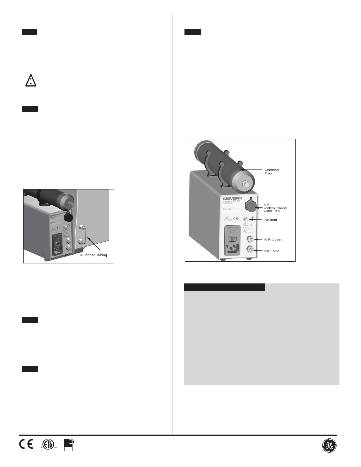
Abbildung 3. Entfernen des U-förmigen Rohrstücks
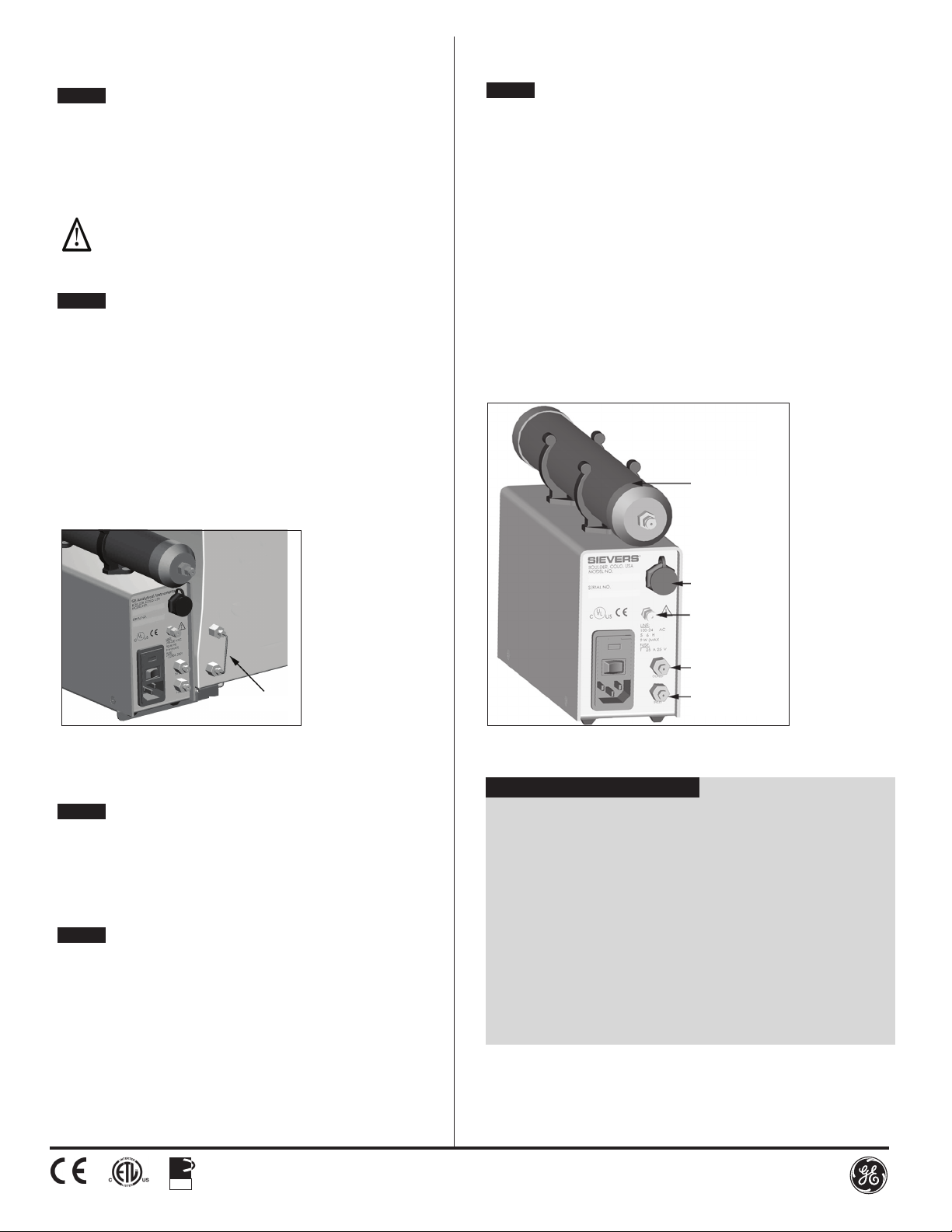
Abbildung 4. Rückansicht des Sievers 900 ICR
Schritt 5 Montieren der ICR-Halterung am Analysator
1. Befestigen Sie die große Montagehalterung, die jetzt am ICR montiert ist, an
der kleinen Montagehalterung.
2. Schieben Sie die große Halterung über die kleine Halterung und
befestigen Sie die Baugruppe, indem Sie die beiden unverlierbaren
Kreuzschlitzstellschrauben festziehen.
_________________________________________________________
HINWEIS: Die ICR-Montagehalterung kann NUR rechts am Analysator
befestigt werden.
Stellen Sie den ICR nicht in der Nähe einer Wärmequelle oder eines
Warmluftauslasses auf.
_________________________________________________________
Schritt 6 Montieren der Probenanschlüsse
Zur Herstellung des Probenusses vom Analysator in den ICR und vom ICR
zurück zum Analysator müssen die Probenanschlüsse montiert werden.
Dies ist eine gesonderte Anweisung in der Betriebs- und Wartungsanleitung des
Analysators unter "Probeneinlasssystem anschließen". Beide Verfahren MÜSSEN
ausgeführt worden sein, bevor der ICR mit dem Analysator in betrieb genommen
werden kann.
1. Halten Sie die Schläuche aus dem ICR-Zubehörkit für dieses Verfahren bereit.
2. Machen Sie sich an der Rückseite des Analysators die mit "Vom ICR" (From
ICR) und "Zum ICR" (To ICR) bezeichneten Ports ausndig. Entfernen Sie das
U-förmige Edelstahl-Rohrstück, indem Sie die Valco-Armaturen mit einem
¼"-Gabelschlüssel lösen (siehe Abbildung 3).
3. Verbinden Sie mit dem Schlauch den mit "Auslass" (Outlet) bezeichneten ICR-
Port mit dem mit "Vom ICR" (From ICR) bezeichneten Analysator-Port. Ziehen
Sie die Valco-Armatur mit einem ¼"-Gabelschlüssel fest.
4. Verbinden Sie mit dem Schlauch den mit "Einlass" (Inlet) bezeichneten ICR-Port
mit dem mit "Zum ICR" (To ICR) bezeichneten Analysator-Port. Ziehen Sie die
Valco-Armatur mit einem ¼"-Gabelschlüssel fest.
Schritt 7 Montieren der elektrischen Anschlüsse
Montieren Sie das ICR-Kommunikationskabel und das AC-Netzkabel am ICR.
1. Schließen Sie ein Ende des ICR-Kommunikationskabels am ICR und das
andere Ende am Analysator an. Eventuell sind an beiden Geräten die
Anschlussabdeckungen zu entfernen, bevor das Kabel montiert werden kann.
2. Schließen Sie das AC-Netzkabel auf der Rückseite des ICRs und mit dem
anderen Ende an einer geerdeten Stromversorgung an.
Schritt 8 Vorbereiten der chemischen Falle
Wenn eine chemische Falle am ICR montiert werden soll, wird der im ICR-
Zubehörkit enthaltene Schlauchsatz benötigt.
1. Halten Sie den Lufteinlassschlauch aus dem ICR-Zubehörkit bereit.
2. Mit dem Schlauch verbinden Sie die chemische Falle mit dem ICR, indem
Sie die Messing-Muttern an jedem Ende des Schlauchs mit einem
5/16"-Gabelschlüssel festziehen.
3. Entfernen Sie den Verschluss (John Guest-Armatur) vorne von der chemischen
Falle, indem Sie die schwarze Basis mit einer Hand nach innen drücken und
die rote Armatur mit der anderen Hand herausziehen.
ISO
9001:2008
QUALITY
MANAGEMENT
SYSTEM
Spezikationen
Leistungsbedarf (100-240) ± 10% VAC, 50/60 Hz, 9 Watt
Sicherungen 0,25 A, 250 V SloBlo (5 X 20 mm)
Umgebungstemperatur 50-104 °F (10 - 40 °C)
Relative Luftfeuchte bis zu 95%, nichtkondensierend
Maximale Höhe 3.000 m (9.843 ft)
Installation/Überspannungskategorie II
Verschmutzungsgrad 2
Abmessungen (Höhe x Breite x Tiefe) 12,2 cm x 8,2 cm x 33,4 cm
(4,8 " x 3,2" x 13,1")
Gewicht 2,6 kg (5,75 lbs.)
Sicherheitszertikate CE, ETL-gelistet. Erfüllt UL-Standard
61010-1, zertiziert nach
CSA C22.2 No. 61010-1.
Schritt 9 Abschließendes Einrichten
1. Vergewissen Sie sich, dass das Probeneinlasssystem am Analysator angeschlossen
ist. Schlagen Sie bei Bedarf in der Betriebs- und Wartungsanleitung des Analysators
nach.
2. Wenn Sie den ICR in Verbindung mit einem tragbaren Analysator verwenden wollen,
montieren Sie den Schlauchführungsclip auf der Rückseite des Analysators und
führen Sie dann das Kommunikationskabel durch den Clip. Der Clip sichert das
Kommunikationskabel, wenn der Analysator mit dem an der Halterung montierten
ICR getragen wird.
3. Etablieren Sie einen Zuuss von Probenwasser, wenn der Analysator als kontinuierlicher
Probendurchuss angeschlossen ist.
4. Schalten Sie den Analysator ein.
5. Schalten Sie den ICR ein.
6. Legen Sie zum Starten des ICR-Betriebs den ICR-Schalter in Inline-Stellung.
7. Wenn Sie manuelle Einstellungen für die Reagenzien-Durchussrate verwenden
möchten, stellen Sie die Durchussrate entsprechend für den Gebrauch mit ICR ein.
Anweisungen benden sich in der Betriebs- und Wartungsanleitung des ICRs unter
"Einstellen der Reagenzien-Durchussraten".
Chemische Falle
Anschluss ICR-
Kommunikationskabel
Lufteinlass
ICR-Auslass (Outlet)
ICR-Einlass (Inlet)