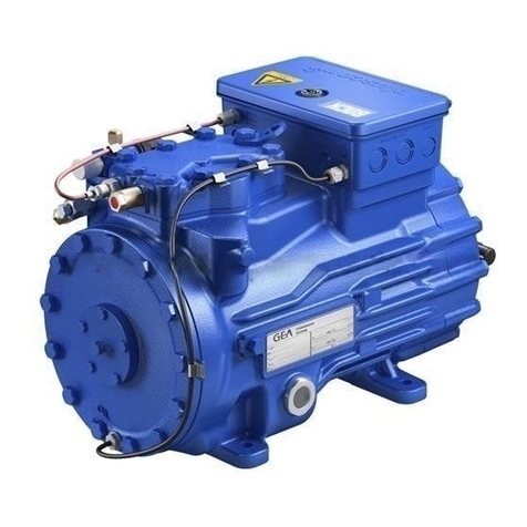
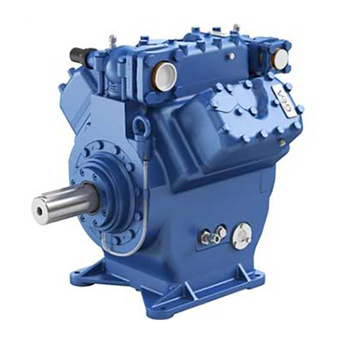
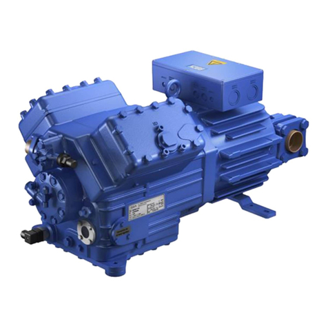
GEA Grasso 5 User manual

Reciprocating compressors for industrial
refrigeration
GEA Grasso V
Installation and Maintenance instructions (Original text)
0089288_imm_v_english_19

COPYRIGHT
All Rights reserved. No part of this publication may be copied or published by
means of printing, photocopying, microfilm or otherwise without prior written
consent of GEA.
This restriction also applies to the corresponding drawings and diagrams.
LEGAL NOTICE
This publication has been written in good faith. However, GEA cannot be held
responsible, neither for any errors occurring in this publication nor for their
consequences.
0089288_imm_v_english_19
2 07.04.2021

SYMBOLS USED
Danger
Stands for an immediate danger leading to severe physical injuries or death.
► Description for avoiding the danger.
Warning!
Stands for a potentially dangerous situation leading to severe physical
injuries or death.
► Description for avoiding the dangerous situation.
Caution!
Stands for a potentially dangerous situation which could lead to minor
physical injuries or damage to property.
► Description for avoiding the dangerous situation.
Notice
Stands for important information that must be observed for the intended use
and function of the product.
► Description of the required action for the intended function of the product.
SAFETY INSTRUCTIONS
Hint!
This manual must be careful read and understood prior to installing
and servicing the compressor (package)
Safety
This manual is written with great care, but the contractor/installer is held
responsible to examine this information and to take care of possible additional
and/ or deviated safety measures.
Safety instructions
It is the task of the contractor/installer to inform and explain to his client the
operation of the compressor (Package).
Do respect all federal, state or local safety regulations/legislations during
installing, connecting and operating this compressor (package).
Construction changes
Warning!
In compliance with the regulations of the Pressure Equipment
Directive it is mandatory that no changes be made to the construction
of pressurised parts such as the crankcase housing, suction filter
housing etc.
0089288_imm_v_english_19
07.04.2021 3

Installer oriented information
The compressor (package) is filled with nitrogen to prevent penetration of
moisture. Therefore, keep the compressor closed until the compressor (package)
is being installed.
Never store the compressor filled with compressed air. Compressed air contains
moisture that will corrode the inside and working components of the compressor.
To store the compressor, fill it with dry nitrogen after fully evacuating it.
Warning!
The compressor, oil filters, oil lines, etcetera, are not filled with oil.
Pre-lubrication is obligatory. Refer Section 4.7, Page 61
Hint!
After the successful initial run of the compressor (package) the
warranty chart must be filled in and returned to Grasso. A warranty
chart is attached to each compressor.
0089288_imm_v_english_19
4 07.04.2021

PREFACE
General
1. All documentation can be downloaded via our web site.
2. GEA technical manuals includes “generic paragraphs”; this means that it can
occur that not all data as described is relevant for the current compressor
series as mentioned in this manual. (For instance, not all compressor series
are suitable for all mentioned refrigerants or not all compressor series
includes two-stage compressors)
Directives
Equipment is based on Pressure Equipment Directive (PED 2014/68/EU)
regulations and according to Machine Directive (MD 2006/42/EG) regulations.
The applied standards are:
NEN-EN-IEC 60204, NEN-EN-ISO 12100, NEN-EN-ISO 13857, NEN-EN 378
0089288_imm_v_english_19
07.04.2021 5

0089288_imm_v_english_19
6 07.04.2021

CYLINDER NUMBERING, BOOSTER AND SINGLE-STAGE OPERATION
Cylinder numbering
Fig.1: Example cylinder numbering 6 cylinder compressor
Booster or single-stage operation
1. Booster operation applies if condensing temperature < +5 oC
2. Single-stage operation applies if condensing temperature >= +5 oC
0089288_imm_v_english_19
07.04.2021 7

0089288_imm_v_english_19
8 07.04.2021

GENERAL INFO
Main setup data
Description
Value
Remark
Grasso V 300 (T) .. V 600 (T) Grasso V 700 (T) .. V 1800 (T)
General limits of operation
Caution!
Refer to Product Information Section 4.2, Page 51
Start frequency max. 6 starts per hour
The NO-solenoid has to be
de-energised 20 seconds
after starting the compressor
motor to enabel the motor to
reach the minimum speed and
the compressor to develop the
required oil pressure.
Time interval between stopping
and re-starting min. 2 minutes
Time interval between starting
and re-starting min. 10 minutes
Time interval between loading
and unloading min. 3 minutes
For continuous minimum part-
load (i.e. more than 30
minutes) consult Grasso.
Adjust the steps between up
and down loading, in such a
way that the system is running
stable.
Oil level 25-75% crankcase sight glass
Control oil pressure suction pressure + 8 bar (g)
Lubricating oil pressure
difference between 1.3 and 4.5 bar Setting approx. 2.0 bar (g)
After a mimimum of 15 minutes
running time at an oil
temperature of approx. 50 oC
Superheat >0 K
Oil discharge - running in -
filter
Factory mounted; to be replaced after max. 100 running hours by “normal” oil discharge filter
element
Oil discharge filter Supplied loose; replacement for factory mounted running in filter
0089288_imm_v_english_19
07.04.2021 9

0089288_imm_v_english_19
10 07.04.2021

TABLE OF CONTENTS
1 INSTALLATION AND PREPARATION FOR USE 13
1.1 Running-in oil filter has to be installed after an overhaul or big repair 13
1.2 Safety valves 13
1.3 INSTALLATION 13
1.3.1 Moving instructions and storage 14
1.3.2 Storage 14
1.3.3 Hoisting and moving instructions 15
1.3.4 Required free space 16
1.3.5 Foundation requirements 16
Concrete structure 17
Anchoring 18
Mounting the base frame on a concrete block 19
Mounting bare compressor on a concrete block 21
1.3.6 Connecting to refrigerating system pipework 21
Torques for factory supplied check valve / stop valve assembly 22
1.3.7 Connecting the power supply 23
1.3.8 Earthing connections 23
1.3.9 Separately delivered components 23
1.4 PREPARATIONS FOR USE 24
1.4.1 Leak test of compressor and system 24
1.4.2 EVACUATION/DRYING THE REFRIGERATING SYSTEM 24
1.4.3 Initial oil charge 24
Oil quantities 25
1.4.4 Initial refrigerant charge 26
1.4.5 Adjustment of instruments and safety devices 26
CONTROL DEVICES 26
PRESSURE SETTINGS 26
RE-ADJUSTMENT OF OIL PRESSURE REGULATORS 27
1.4.6 Checking direction of rotation of motor shaft 29
1.4.7 Installing the drive guards (if present) 29
1.4.8 Initial oil warm up 29
1.4.9 Initial start-up 29
Limitations of part load operation and start-up 29
WIRING LOGIC NORMALLY OPEN UNLOADED START SOLENOID 29
Frequency controlled compressor 30
Pre-start check list 30
1.4.10 Starting and stopping procedures 30
First start 30
Restart 31
Restart after a short standstill period of time (less than 1 month) 31
Restart after a long standstill period of time 32
Stopping the compressor 32
2 INSPECTION AND TROUBLE SHOOTING 33
2.1 Periodical inspection 33
2.2 Survey of periodical inspections 33
2.2.1 Check list periodical inspection 34
2.3 STEPS FOR LONGER SHUT-DOWN PERIODS (> 6 months) 34
2.4 LUBRICATION DATA 35
2.4.1 Topping up oil with compressor operating 35
2.5 EVACUATION, LEAK TESTING AND START-UP OF THE COMPRESSOR/PACKAGE 35
2.5.1 EVACUATION OF REFRIGERANT BEFORE SERVICING 36
2.5.2 LEAK-TIGHTNESS AFTER SERVICING 36
2.5.3 EVACUATION AFTER SERVICING 36
2.5.4 START-UP AFTER SERVICING 36
2.6 DRAINING AND CHANGE OF OIL 37
2.7 REPLACEMENT OF OIL FILTERS 37
2.8 DISMANTLING, INSPECTION AND RE-ASSEMBLY OF SUCTION AND DISCHARGE VALVES 38
2.9 COMPRESSOR PURGING 38
2.10 TROUBLESHOOTING TABLE GRASSO RECIPROCATING COMPRESSORS 39
3 MAINTENANCE 42
0089288_imm_v_english_19
07.04.2021 11

3.1 Spare parts manual 42
3.2 Post start-up maintenance 42
3.3 First maintenance 42
3.4 SERVICE MAINTENANCE SCHEDULE 43
3.4.1 Description Maintenance A, B and C 43
3.4.2 EXPLANATION SERVICE ACTIVITIES 45
3.4.3 Maintenance compressor V (HS, HP) Series 45
Maintenance table V (HS, HP) Series, part 1 of 3 47
Maintenance table V (HS, HP) Series, part 2 of 3 48
Maintenance table V (HS, HP) Series, part 3 of 3 49
Most operated cylinders 49
3.4.4 Package components 50
4 APPENDIX; Product Information (PI) 51
4.1 GRASSO MAINTENANCE MONITOR 51
4.2 GENERAL LIMITS OF OPERATION GRASSO V 51
4.3 STARTING UP OF TWO-STAGE COMPRESSORS 53
4.4 DIAGRAMS SINGLE STAGE AND BOOSTER 55
4.5 DIAGRAMS TWO STAGE 57
4.6 LUBRICATING OILS (choice and recommendations) 59
4.6.1 STRONGLY RECOMMENDED OIL TYPES 59
4.6.2 ACCEPTED NH3 OIL TYPES 60
4.6.3 Lubricating Oil for Refrigerating Compressors in systems with an add on Heat Pump 60
4.7 Pre-lubrication oil system 61
0089288_imm_v_english_19
12 07.04.2021

1 INSTALLATION AND PREPARATION FOR USE
1.1 Running-in oil filter has to be installed after an overhaul or big repair
Hint!
This is why and when the running in oil filters are required:
Warning!
A running in oil filter has always to be installed after an overhaul or
big repair for 100 .. 200 hours of operation!
The oil and oil filters have to be replaced by new oil and filters.
Due to running-in wear of liners and piston rings, it's normal that the
oil becomes grey during 100 .. 200 operating hours.
After 100 .. 200 operating hours, the oil could slightly become clear
again.
1.2 Safety valves
Danger
If the package includes an oil separator, be sure that a (dual) safety
valve (GEA option) is fitted onto oil separator.
Hint!
The contractor is responsible for arranging the (dual) safety valve
according the Pressure Equipment Directive 2014/68/EU.
1.3 INSTALLATION
Warning!
The compressor is not charged with oil, therefore, DO NOT start the
compressor before it has been installed and prepared according to
Grasso’s instructions.
This section contains instructions for the proper installation of a Grasso
compressor (package). Before the compressor (package) is ready for the initial
start up, the installation instructions in the following paragraphs must be followed:
1. The Compressor (Package) should be levelled and securely anchored to the
foundation.
2. All piping should be completed.
3. The system and the compressor are to be pressure tested for leaks (see.
Section 1.4.1, Page 24)
4. The system should be evacuated to remove air and moisture.
INSTALLATION AND PREPARATION FOR USE
Running-in oil filter has to be installed after an overhaul or big repair
0089288_imm_v_english_19
07.04.2021 13

5. The electric wiring should be completed as per wiring diagrams. Do not
energise the main power control cabinet until oil is added and the direction of
rotation has been checked.
6. The compressor is to be filled with the correct type and amount of lubricating
oil and has to be pre-lubricated (Refer Section 4.7, Page 61) before the first
start.
7. The drive system should be installed.
8. The system should be charged with the correct amount of refrigerant.
9. The oil should be warmed up above minimum start up oil temperature (see
"Product Information").
10. The control cabinet should be energised to check the package controls.
Hint!
Do not forget to charge the oil separator initially with oil, to the level of
the float assembly
1.3.1 Moving instructions and storage
For loose component or compressor package weights, refer either to the relevant
component type plate or package lay-out or to the suppliers document. For bare
compressor weights, see "Product Information".
Caution!
Every precaution must be taken while moving the package to its final
location. Pushing, pulling or climbing on any package component or
piping, can easily create damage.
1.3.2 Storage
The compressor (package) is filled with dry nitrogen. Keep the system closed
until the package is installed. If the compressor (package) is stored, it should be
kept at all times in a dry location to prevent corrosion damage. If the compressor
(package) is to be stored for a prolonged period of time, it should be checked
weekly to ensure that the holding charge of dry nitrogen remains above
atmospheric pressure.
INSTALLATION AND PREPARATION FOR USE
INSTALLATION
0089288_imm_v_english_19
14 07.04.2021

1.3.3 Hoisting and moving instructions
Fig.2: Hoisting a compressor package
Packaged base frame:
The only places that can be used for safe hoisting of the package are the four
hoisting eyes on the steel base frame as shown in the above figure. Prior to
hoisting a compressor package with a V-belt drive arrangement, the factory
mounted drive guard has to be removed. Attach spreader bars to the slings so as
to prevent damage to piping and components.
Warning!
DO NOT use the compressor or motor or oil separator hoisting eyes to
move the package! These hoisting eyes are intended for lifting loose
components only and not for the entire package!
Bare compressor or loose components:
Determine the dead weight of the particular component (see "Product Information
(ED)"), prior to moving a bare compressor or loose component. Use the hoisting
eyes only, DO NOT sling from other compressor parts (see Figure 3, Page 16).
INSTALLATION AND PREPARATION FOR USE
INSTALLATION
0089288_imm_v_english_19
07.04.2021 15

Fig.3: Hoisting angle
Moving by fork-lift truck
The bare compressor or package can be transported with a fork-lift truck with the
forks spread as much as possible between the skids. To simplify moving, the 2
wooden transport beams must still be mounted underneath the base frame and
stored in this way, until the package is positioned above its approximate location.
1.3.4 Required free space
For easy operating, servicing and maintenance access, the compressor
(package) should be installed with sufficient free space around it.
Hint!
Refer to “Product Information“ for minimum requirements.
1.3.5 Foundation requirements
Hint!
Compressor (package) has to be mounted on a concreted block. On
request, Grasso can calculate the exact dimensions of the concrete
block, based on the compressor size and operating conditions.
This paragraph covers measures to be taken for a compressor (package)
mounting on a concrete block.
Two foundation arrangements are described:
INSTALLATION AND PREPARATION FOR USE
INSTALLATION
0089288_imm_v_english_19
16 07.04.2021

1. Compressor package with steel base frame mounted on a concrete block.
Following base frames are possible;
1.a Frame designed for mounting on concrete block.
For more instalation details refer to; Section 1.3.5.1, Page 17,
Section 1.3.5.2, Page 18, Section 1.3.5.3, Page 19, Section ,
Page 20, Section , Page 20.
1.b Frame designed for mounting on vibration dampers.
For more details in case mounting base frames on vibration dampers is
applied, refer to separate instruction sheet and other order
documentation like package drawing, supplied with the compressor
package and consult Grasso if required.
2. Bare compressor direct mounted on a concrete block via grouted anchors.
For more installation details refer to; Section 1.3.5.1, Page 17,
Section 1.3.5.2, Page 18, Section 1.3.5.4, Page 21.
1.3.5.1 Concrete structure
Fig.4: Concrete block
1 Cork board
2 Concrete base
3 (Concrete) Floor
4 Sand
The concrete block for compressor and motor or compressor package should
have a profile as illustrated in Page 17 and made according to the following
recommendations:
•The concrete block should be set on firm footings or on a floor capable of
carrying the weight of the concrete block and capable of absorbing the free
forces and gas forces of the compressor during operation. The ground under
the concrete block should be horizontal and flat.
•The top surface of the block should be level and even.
•There should be sufficient free space around the block to install corkboard (or
similar).
•The block should be provided with anchor bolt recesses or holes according to
the anchor bolt spacing as per package lay out drawing.
INSTALLATION AND PREPARATION FOR USE
INSTALLATION
0089288_imm_v_english_19
07.04.2021 17

Fig.5
A Chemical anchor
B Grouted anchor, grounded to reinforcing steel
It is recommended to consult a concrete specialist/ constructor for the following
items:
•The compound of the concrete with/without reinforcement.
•The exact grouting depth (dependent on the soil conditions).
•Installing foundation onto an existing floor, with sealing corkboard or vibration
isolators.
1.3.5.2 Anchoring
After the concrete block has cured the anchors should be installed as shown
above and in case of a package in accordance with the package lay out drawing.
Templates should be made to locate the anchor bolts or chemical anchors to
match the holes in the bottom flange of the base frame.
Grout the mortar according to the supplier instructions. Install chemical anchors
as illustrated in Figure 6, Page 19 and according to the instructions of the
anchor supplier.
INSTALLATION AND PREPARATION FOR USE
INSTALLATION
0089288_imm_v_english_19
18 07.04.2021

Fig.6: Anchoring details
A Drilled chemical anchor (M20)
B Grouted anchor recesses (M20)
1 Installed chemical anchor before placing the base frame
2Installing chemical anchor after placing the base frame (base frame cannot be removed
easily)
3 Drilling angle
1.3.5.3 Mounting the base frame on a concrete block
General
After the space between base frame and concrete base has been filled-up with a
filling grout, the package base frame must be secured tightly to the foundation
block or floor.
INSTALLATION AND PREPARATION FOR USE
INSTALLATION
0089288_imm_v_english_19
07.04.2021 19

Caution!
Do not tighten the anchor bolts until grout has fully cured.
Levelling the base frame
Fig.7: Grouting details
1 Self-levelling grout
2 Adjusting bolts (4x, not included)
3 Washer
4 Temporary barrier strip around and inside frame
5 Complete cured concrete block
6 Grout layer
After the anchor filling mortar has completely cured the frame should be levelled
with a space between block and lower frame flange of 3 - 5 mm*. This space is
necessary for levelling using the base frame adjusting bolts with metal washers
(not included). The base frame should be levelled on each frame side. Adjust the
frame on each adjusting place until all frame sides are horizontal.
This space largely depends on the sort of grout or mortar used. Determine this
space according to the instructions of the grout or mortar supplier.
Finishing with a self-levelling grout
After levelling has been completed the adjusting bolt ends must be greased to
avoid bonding to the self-levelling grout. The space between concrete block and
frame must be completely filled with the self-levelling grout to ensure that the
complete bottom surface of the base frame will be supported. Therefore, it is not
allowed to use shims between concrete base and base frame.
INSTALLATION AND PREPARATION FOR USE
INSTALLATION
0089288_imm_v_english_19
20 07.04.2021
Table of contents
Other GEA Air Compressor manuals

GEA
GEA HG5/725-4 User manual

GEA
GEA HG22e/125-4 User manual

GEA
GEA HGX46/280-4 ML CO2T User manual

GEA
GEA F Series User manual

GEA
GEA HG4/310-4 User manual

GEA
GEA HGX7 R134a User manual

GEA
GEA Bock HGX46 CO2 T Series User manual

GEA
GEA HG22e/160-4 User manual

GEA
GEA GEA Bock HG66e Series User manual

GEA
GEA HGX4 R134a User manual

GEA
GEA Bock HGX2/70-4 CO2 T User manual

GEA
GEA FK40 Series User manual

GEA
GEA Bock HGZ Series User manual

GEA
GEA HG44e User manual

GEA
GEA HGX12e S CO2 User manual

GEA
GEA HG88e series User manual

GEA
GEA HG6/1080-4 User manual

GEA
GEA HGX5/725-4 R134a User manual

GEA
GEA Bock F76 Series User manual

GEA
GEA Grasso User manual