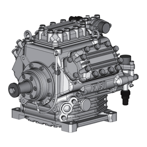
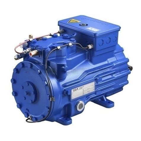
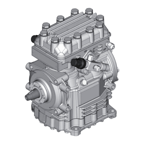
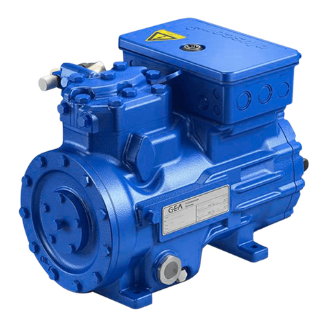
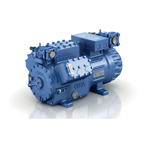
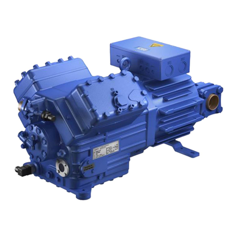
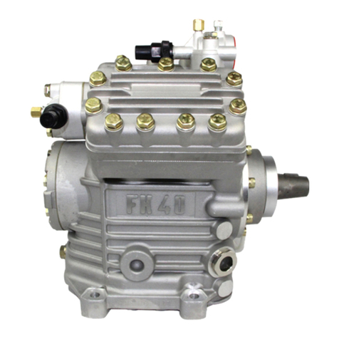
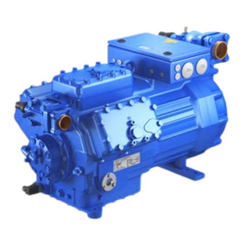
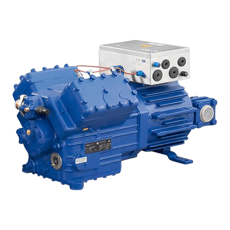
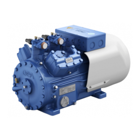
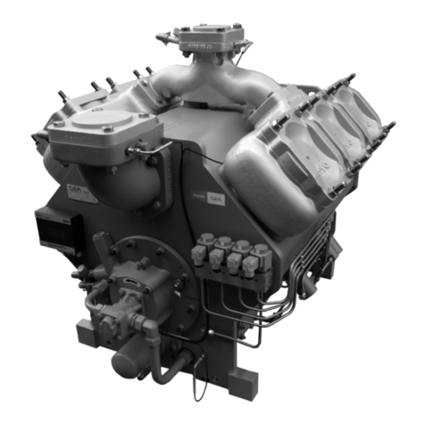
GEA Bock F76 Series User manual

GEA Bock F76
F76/1570 FX76/1570
F76/1800 FX76/1800
F76/2050 FX76/2050
F76/2425 FX76/2425
Assembly instructions
96438-02.2020-Gb
Translation of the
original instructions

2
GB
GB
F
E
96438-02.2020-DGbRu
About these instructions
Read these instructions before assembly and before using the compressor. This will avoid misunder-
standings and prevent damage. Improper assembly and use of the compressor can lead to serious
or fatal injury.
Observe the safety instructions contained in these instructions.
These instructions must be passed onto the end customer along with the unit in which the compres-
sor is installed.
GEA Bock GmbH
72636 Frickenhausen
GEA Bock GmbH
Benzstraße 7
72636 Frickenhausen
Germany
Telephone +49 7022 9454-0
Fax +49 7022 9454-137
gea.com
gea.com/contact
Manufacturer
Contact

GB
GB
F
E
3
96438-02.2020-DGbRu
Contents Page
1 Safety 4
1.1 Identication of safety instructions
1.2 Qualications required of personnel
1.3 Safety instructions
1.4 Intended use
2 Product description 6
2.1 Short description
2.2 Name plate
2.3 Type code
3 Areas of application 8
3.1 Refrigerants
3.2 Oil charge
3.3 Operating limits
4Compressor assembly 10
4.1 Storage and transport
4.2 Setting up
4.3 Maximum permissible inclination
4.4 Pipe connections
4.5 Pipes
4.6 Start unloader (external)
4.7 Laying suction and discharge lines
4.8 Operating the shut-off valves
4.9 Operating mode of the lockable service connections
4.10 Drive
5 Commissioning 16
5.1 Preparations for start-up
5.2 Pressure resistance test
5.3 Leak test
5.4 Evacuation
5.5 Refrigerant charge
5.6 Shaft seal
5.7 Start-up
5.8 Avoiding slugging
5.9 Oil separator
6 Maintenance 19
6.1 Preparation
6.2 Work to be carried out
6.3 Spare parts recommendation
6.4 Shaft seal change
6.5 Excerpt from the lubricant table
6.6 Decommissioning
7 Accessories 20
7.1 Oil sump heater
7.2 Capacity regulator
7.3 Elevated base plate
8 Technical data 23
9 Dimensions and connections 24
10 Declaration of incorporation 26
11 Service 27

4
GB
GB
F
E
96438-02.2020-DGbRu
1.1 Identication of safety instructions
1|Safety
1.2 Qualications required of personnel
WARNING Inadequately qualied personnel poses the risk of accidents, the
consequence being serious or fatal injury. Work on compressors
is therefore reserved for personnel which is qualied to work on
pressurized refrigerant systems:
• For example, a refrigeration technician, refrigeration mechatronic engi-
neer. As well as professions with comparable training, which enables
personnel to assemble, install, maintain and repair refrigeration and
air-conditioning systems. Personnel must be capable of assessing the
work to be carried out and recognising any potential dangers.
DANGER Indicates a dangerous situation which, if not avoided,
will cause immediate fatal or serious injury.
WARNING Indicates a dangerous situation which, if not avoided,
may cause fatal or serious injury.
CAUTION Indicates a dangerous situation which, if not avoided,
may cause fairly severe or minor injury.
ATTENTION Indicates a situation which, if not avoided,
may cause property damage.
INFO Important information or tips on simplifying work.

GB
GB
F
E
5
96438-02.2020-DGbRu
These assembly instructions describe the standard version of the compressor named in the title
manufactured by GEA Bock. GEA Bock refrigerating compressors are intended for installation in a
machine (within the EU according to the EU Directives 2006/42/EC Machinery Directive, 2014/68/EU
Pressure Equipment Directive).
Commissioning is permissible only if the compressor has been installed in accordance with these as-
sembly instructions and the entire system into which it is integrated has been inspected and approved
in accordance with legal regulations.
The compressors are intended for use in refrigeration systems in compliance with the limits of
application.
Only the refrigerant specied in these instructions may be used.
Any other use of the compressor is prohibited!
1.4 Intended use
1.3 Safety instructions
WARNING Risk of accidents.
Refrigerating compressors are pressurised machines and as such
call for heightened caution and care in handling.
The maximum permissible overpressure must not be exceeded,
even for testing purposes.
Risk of burns!
- Depending on the operating conditions, surface temperatures of
over 60 °C on the discharge side or below 0 °C on the suction side
can be reached.
- Avoid contact with refrigerant necessarily.
Contact with refrigerant can cause severe burns and skin
damage.
WARNING The compressor may not be used in potentially explosive
environments!
1|Safety

6
GB
GB
F
E
96438-02.2020-DGbRu
2|Product description
6-cylinder open type compressor for external drive (V-belt or coupling)
with oil pump lubrication
2.1 Short description
Fig. 1
Fig. 2
Transport eyelet
Discharge
shut-off valve
Cylinder cover
Valve plate
Suction
shut-off valve
Leak oil
drain hose
Shaft end
Shaft seal
Base plate
Dimension and connection values can be found in Chapter 9.
Name plate
Oil pump
Sight glass

GB
GB
F
E
7
96438-02.2020-DGbRu
/
F76 2425
X
Fig. 3
2.3 Type code (example)
¹) X - Ester oil charge (HFC refrigerant R134a, R404A/R507, R407C)
Swept volume
Size
Oil charge ¹)
Series
2.2 Name plate (example)
1
2
3
4
5
6
FX76/2425
500 72,8
261,9
BC12756A001
SE55
19/28
GEA Bock GmbH
72636 Frickenhausen, Germany
Observe the limit of
application diagrams!
1 Type designation
2 Machine number
3 Rotation speed minimum with a corresponding displacement
4 Rotation speed maximum with a corresponding displacement
5 ND(LP): Max. admissible operating pressure Suction side
HD(HP): Max. admissible operating pressure
High-pressure side
6 Oil type charged at factory
2|Product description

8
GB
GB
F
E
96438-02.2020-DGbRu
3|Areas of application
The compressors are lled with the following oil type at the factory:
- for R134a, R404A/R507, R407C FUCHS Reniso Triton SE 55
- for R22 FUCHS Reniso SP 46
Compressors with ester oil charge (FUCHS Reniso Triton SE 55) are marked with an X in the type
designation (e.g. FX76/2425).
3.1 Refrigerants
• HFKW / HFC: R134a, R404A/R507, R407C
• (H)FCKW / (H)CFC: R22
3.2 Oil charge
INFO For refilling, we recommend the above oil types.
Alternatives: see lubricants table, Chapter 6.4
ATTENTION The correct oil level is shown
in Figure 4.
Damage to the compressor
is possible if overfilled or
underfilled!
max.
min.
1.3 Ltr.
oil level
Fig. 4
~
~
3.3 Operating limits
ATTENTION Compressor operation is possible within the operating limits shown
in the diagrams. Please note the signicance of the shaded areas.
Thresholds should not be selected as design or continuous operat-
ing points.
- Permissible ambient temperature (-20 °C) - (+60 °C)
- Max. permissible discharge end temperature: 140 °C
- Max. permissible switching frequency: Please refer to the
instructions of the engine manufacturer.
- A minimum running time of 3 min. steady-state condition
(continuous operation) must be achieved.
Avoid continuous operation near the threshold.
For operation with supplementary cooling:
- Use only oils with high thermal stability.
For operation with capacity regulator:
- The suction gas superheat temperature may need to be reduced
or set individually when operating near to the threshold.
When operating in the vacuum range, there is a danger of air
entering on the suction side. This can cause chemical reactions, a
pressure rise in the condenser and an elevated compressed-gas
temperature. Prevent the ingress of air at all costs!

GB
GB
F
E
9
96438-02.2020-DGbRu
R134a
Fig. 5
R404A/R507
Fig. 6
R407C
Fig. 7
R22
Fig. 8
>10K
0
0
0
3.3 Operating limits
Unlimited
application range
Reduced suction gas
temperature
Evaporating temperature (°C)
Condensing temperature (°C)
Suction gas superheat (K)
Suction gas temperature (°C)
Permissible rotation speeds:
500 - 1800 rpm
Maximum permissible
operating pressure
(LP/HP)1): 19/28 bar
Design for other
areas on request
1) LP = Low pressure
HP = High pressure
3|Areas of application

10
GB
GB
F
E
96438-02.2020-DGbRu
Fig. 11
4|Compressor assembly
INFO New compressors are factory-lled with inert gas. Leave this ser-
vice charge in the compressor for as long as possible and prevent
the ingress of air. Check the compressor for transport damage
before starting any work.
?
4.1 Storage and transport
Use transport eyelet.
Do not lift manually!
Use lifting gear with sufcient load capacity!
Transport and suspension unit on the eyebolt (Fig. 11).
Storage at (-30 °C) - (+70 °C), maximum permissible relative
humidity 10 % - 95 %, no condensation
Do not store in a corrosive, dusty, vaporous atmosphere or in a com-
bustible environment.
Fig. 10
Fig. 9

GB
GB
F
E
11
96438-02.2020-DGbRu
Fig. 12
Fig. 13
Fig. 14
F
E
D
C
B
A
1
2
3
4
F
E
D
C
4
3
2
1
A
B
Tol.-Ang. DIN ISO 2768-mK
Ra Rz
Maß
Passung
Freigabe
Alternativbezug:
Baumustergeprüft
Teil inaktiv
Lieferantenzeichnung
-
-
K.-Auftrag:
PL:
Zeichnung ungültig
Entwicklungsstand
Teil keine Serie
120
400
±0.5
über 0.5
bis 6
Benzstraße 7 - 72636 Frickenhausen - Germany - www.bock.de
-
-
Unbemaßte Radien:
-
Diese Zeichnung ist unser Eigentum!
Sie darf ohne unsere Genehmigung weder nach-
gebildet, vervielfältigt, oder Dritten Personen zu-
gänglich gemacht werden. Der Nachbau nach
dieser Zeichnung, oder an Hand der nach dieser
Zeichnung hergestellten Gegenstände durch den
Abnehmer oder Dritte ist nicht gestattet.
Wir behalten uns alle Rechte, gemäß DIN ISO 16016
an dieser Zeichnung vor.
Bearb.
Datum
Änderungs-Nr.
Werkstoff:
Ausgangsteil, bzw. Rohteil:
--
Gepr.
Name
Datum
19.04.
Werkstückkanten
DIN ISO 13715
Ersatz für:
Ersetzt durch:
Erstellt
2010
Geprüft
-
Kurz
Zone
1/x
Oberflächenbehandlung / Härte:
-
Blatt:
Änderungsbeschreibung
400
Benennung:
±0.8
1000
30
6
-
±0.3
120
30
±0.2
Zeichn.-Nr. Teile-Nr.
Oberflächenangaben ISO 1302
x.xxxx-xxxxx.x
Zust.
Gußtoleranzen:
Gewicht: (kg)
±0.1
Maßstab:
1:1
Wasserwaage
für Indesign
Der Lieferant muß sicherstellen, dass die Ware in
einwandfreiem Zustand angeliefert wird (Korrosions-
schutz, Verpackung für sicheren Transport).
Rz 25
Rz 160
s
25
z
y
x
w
u
t
0,05
Rz 1,6
0,3
0,7
1,6
2
Rz 16
6,3
Rz 63
Rz 6,3
Rz 12,5
F:\user\kurz\3D Sachen\3D Teile\Zeichnungen\Wasserwaage
4.3 Maximum permissible inclination
Fig. 15
A A
aa
A A
aa
ATTENTION Risk of compressor damage.
Poor lubrication can damage the compressor.
Respect the stated values.
Amax. 30°,
max. 2 minutes
amax. 15°,
continuous
operation
4.2 Setting up
Compressors and drive motors are basically rigid and should be
mounted together on a base frame.
Provide adequate clearance for maintenance work.
Provide adequate ventilation for the drive motor.
Do not use in a corrosive, dusty, damp atmosphere or a
combustible environment.
Setup on an even surface or frame with sufcient load-bearing
capacity. Use all 4 fastening points.
Correct setup of the compressor and mounting of the belt drive are
decisive for running comfort, operating safety and the service life of
the compressor.
ATTENTION Attachments (e.g. pipe holders, additional units, fastening parts,
etc.) directly to the compressor are not permissible!
4|Compressor assembly

12
GB
GB
F
E
96438-02.2020-DGbRu
The pipe connections have stepped internal diameters so that pipes with
standard millimetre and inch dimensions can be used.
The connection diameters of the shut-off valves are designed for maximum
compressor output. The required pipe cross-section must be matched
to the capacity. The same applies for non-return valves.
The required tightening torque for the ange connection is 60 Nm.
Fig. 17
4.4 Pipe connections
ATTENTION Risk of damages.
Overheating can damage the valve.
Remove the pipe supports from the valve for soldering.
Only solder using inert gas to inhibit oxidation products (scale).
4.6 Start unloader (external)
An internal start unloader ex factory is not available. Alternatively a start unloader can be installed
in the plant.
Operation:
When the compressor is started, a solenoid valve receives power via a time switch and opens a by-
pass between the discharge- and suction line. At the same time, a non-return valve in the discharge
line closes and prevents a backow of refrigerant from the condenser (Fig. 17).
The compressor is now short-circuited and delivers from the outow directly into the intake. The
pressure differential consequently decreases substantially. As a result, the torque on the drive shaft
of the compressor is considerably diminished. The drive motor can now start with a low level of
starting torque. As soon as the motor and the compressor reach their rated speed, the solenoid valve
closes and the non-return valve opens (Fig. 18). The compressor now works under normal load.
Fig. 16: stepped
internal diameters
4.5 Pipes
Pipes and system components must be clean and dry inside and free of scale, swarf and layers of
rust and phosphate. Only use air-tight parts.
Lay pipes correctly. Suitable vibration compensators must be provided to prevent pipes being
cracked and broken by severe vibrations.
Ensure a proper oil return.
Keep pressure losses to an absolute minimum.
Solenoid valve actuated
Non-return valve closed
4|Compressor assembly

GB
GB
F
E
13
96438-02.2020-DGbRu
Fig. 19
4.7 Laying suction and discharge lines
A rule of thumb: Always lay the rst pipe section starting from the shut-off valve downwards
and parallel to the drive shaft.
ATTENTION Improperly installed pipes can cause cracks and tears, the result
being a loss of refrigerant.
INFO Proper layout of the suction and discharge lines directly after
the compressor is integral to the system’s smooth running and
vibration behaviour.
Important:
- Start unloader may only be employed during the starting phase.
- Check the solenoid valve and the non-return valve regularly for tightness.
- In addition, we recommend to use a heat protection thermostat on the discharge side of the com-
pressor. This protects the compressor against thermal overloading. Connect the heat protection
thermostat in series on the safety chain of the control circuit, to switch off the compressor if
necessary.
- Follow these instructions to avoid thermal overloading.
Fig. 18
Solenoid valve dead
Non-return valve open
Rigid
xed point
As short as possible
4|Compressor assembly

14
GB
GB
F
E
96438-02.2020-DGbRu
4.8 Operating the shut-off valves
Before opening or closing the shut-off valve, release the valve spindle seal by approx. 1/4of a
turn counter-clockwise.
After activating the shut-off valve, re-tighten the adjustable valve spindle seal clockwise.
Fig. 20 Fig. 21
4.9 Operating mode of the lockable service connections
Fig. 22
Opening the shut-off valve:
Spindle: turn to the left (counter-clockwise) as far as it will go.
—> The shut-off valve is then fully open and the service connection is closed.
Fig. 23
Opening the service connection
Spindle: 1/2- 1 rotation to the right (clockwise).
—> The service connection is then open and the shut-off valve is also open.
Spindle
Spindle
Valve spindle seal
loosen
tighten
After activating the spindle, generally t the spindle protection cap again and tighten with 14 - 16 Nm.
This serves as a second sealing feature during operation.
Pipe connection
Pipe connection
Compressor
Compressor
Connection
blocked
Connection
open
Service connection
closed
Service connection
opened
4|Compressor assembly

GB
GB
F
E
15
96438-02.2020-DGbRu
4.10 Drive
The compressors can be driven by V-belts or directly by shaft couplings.
V-belt:
Proper assembly of belt drive:
- The pulleys of compressor and drive motor must be rmly mounted and in line.
- Only use V-belts with calibrated lengths.
- Select axis spacing, V-belt length and belt pre-tension according to the instructions issued by
the V-belt manufacturer. Avoid belt uttering.
- Check belt pre-tension after running-in time.
- Maximum permissible axle load due to belt tension force: 9500 N.
Direct drive with shaft coupling:
Direct drive with shaft couplings demands highly precise aligning of compressor shaft and
motor shaft.
GEA Bock recommends the direct drive with centring a coupling housing (accessory).
ATTENTION Faulty alignment results in premature failure of the coupling and
bearing damage!
CAUTION Risk of injury.
Mount suitable safeguards when driving the compressor by means
of V-belts or shaft couplings!
Fig. 24 (schematical)
Fig. 25 (schematical)
D
GB
F
E
15
96246-09.2012-DGb
4|Montage Verdichter
Während des Verdichterstillstands kann in Abhängigkeit von Druck und Umgebungstemperatur
Kältemittel in das Schmieröl des Verdichters diffundieren. Die Schmierfähigkeit des Öls wird da-
durch herabgesetzt. Beim Anfahren des Verdichters dampft durch die Druckabsenkung das im Öl
enthaltene Kältemittel aus. Die Folgen können Mangelschmierung, Ölaufschäumen und Ölabwan-
derung sein, die unter Umständen zu Verdichterschäden führen können.
Um dem Vorzubeugen, muss das Schmieröl mittels einer Ölsumpfheizung vorgewärmt werden.
Betriebsweise: Ölsumpfheizung EIN bei Stillstand des Verdichters.
Ölsumpfheizung AUS bei Betrieb des Verdichters
Anschluss: Die Ölsumpfheizung über einen Hilfskontakt (oder parallel geschalteten
Hilfsschütz) des Motorschützes an einen getrennten Strompfad anschließen.
Elektrische Daten: 230 V - 1 - 50/60 Hz, 200 W.
4.9 Ölsumpfheizung (Zubehör)
ACHTUNG Da die Ölsumpfheizung auch bei einer Anlagenstörung funktio-
nieren muss, darf die Ölsumpfheizung nicht an den Strompfad
der Sicherheits-Steuerkette angeschlossen werden.
4|Compressor assembly

16
GB
GB
F
E
96438-02.2020-DGbRu
5.3 Leak test
5.4 Evacuation
First evacuate the system and then include the compressor in the evacuation process.
Relieve the compressor pressure.
Open the suction and pressure line shut-off valves.
Evacuate the suction and discharge pressure sides using the vacuum pump.
At the end of the evacuation process, the vacuum should be < 1.5 mbar when the pump is switched off.
Repeat this process as often as is required.
The compressor has been tested in the factory for pressure integrity. If however the entire system is
to be subjected to a pressure integrity test, this should be carried out in accordance with EN 378-2
or a corresponding safety standard without the inclusion of the compressor.
Carry out the leak test on the refrigerating plant in accordance with EN 378-2 or a corresponding
safety standard, while always observing the maximum permissible overpressure for the compressor.
DANGER Risk of bursting!
The compressor must only be pressurised using nitrogen (N2).
Never pressurise with oxygen or other gases!
The maximum permissible overpressure of the compressor must
not be exceeded at any time during the testing process (see name
plate data)! Do not mix any refrigerant with the nitrogen as this
could cause the ignition limit to shift into the critical range.
5|Commissioning
5.2 Pressure strength test
5.1 Preparations for start-up
The compressor has undergone trials in the factory and all functions have been tested. There are
therefore no special running-in instructions.
Check the compressor for transport damage!
INFO To protect the compressor against inadmissible operating conditions,
high pressure and low pressure pressostats are mandatory on the
installation side.
ATTENTION If the capacit y regulator is mounted at the factory, the control com-
ponent (pilot valve) is mounted and connected subsequently by the
customer. If the control component is not connected, the cylinder
bank is switched off permanently. Damage to the compressor is
possible! See chapter 7.

GB
GB
F
E
17
96438-02.2020-DGbRu
Make sure that the suction and discharge line valves are open.
With the compressor switched off, add the liquid refrigerant directly to the condenser or receiver,
breaking the vacuum.
If the refrigerant needs topping up after starting the compressor, it can be topped up in vapour
form on the suction side, or, taking suitable precautions, also in liquid form at the inlet to the
evaporator.
5.5 Refrigerant charge
5.6 Shaft seal
The compressor shaft is sealed to outside using a shaft seal. The sealing element rotates with the
shaft.
The following is especially important to ensuring fault-free operation:
The complete refrigerant circuit must be correctly executed and clean inside.
Heavy shocks and vibrations to the shaft as well as continuous cyclic operation are to be avoided.
The sealing surfaces can stick together during prolonged downtimes (e.g. winter). Therefore, run
the system every 4 weeks for 10 minutes.
CAUTION Risk of injury!
Contact with refrigerant can cause severe burns and skin damage.
Avoid contact with refrigerant and wear personal protective
clothing such as goggles and protective gloves!
ATTENTION Avoid overlling the system with refrigerant!
To avoid shifts in concentration, zeotropic refrigerant blends must
always only be lled into the refrigerating plant in liquid form.
Do not pour liquid coolant through the suction line valve on
the compressor.
It is not permissible to mix additives with the oil and
refrigerant.
ATTENTION Failure to observe the following instructions can cause loss of
refrigerant and damage to the shaft seal!
INFO The shaft seal lubricates and seals with oil. An oil leakage of
0.05 ml per operating hour is therefore normal. This applies
particularly during the run-in phase (200 - 300 h).
The compressor is equipped with an integrated leak oil drain
hose. Through a drain hose leak oil can be drained.
Dispose of the leak oil in accordance with the valid national regu-
lations.
5|Commissioning

18
GB
GB
F
E
96438-02.2020-DGbRu
5.7 Start-up
Check that the safety and protection devices (pressure switch, motor protection, electrical
contact protection measures, etc.) are all functioning properly.
Switch on the compressor and allow to run for a minimum of 10 min.
Check the oil level by: The oil must be visible in the sight glass.
5.8 Avoiding slugging
To prevent slugging:
The complete refrigeration system must be properly designed.
All components must be compatibly rated with each other with regard to output
(particularly the evaporator and expansion valves).
Suction gas superheat at the compressor input should be min. 7 - 10 K. (check the setting
of the expansion valve).
The system must reach a state of equilibrium.
Particularly in critical systems (e.g. several evaporator points), measures are recommended such
as replacement of liquid traps, solenoid valve in the liquid line, etc.
There should be no movement of coolant whatsoever while the compressor is at
a standstill.
WARNING Ensure that both shut-off valves are open before starting the
compressor!
ATTENTION If larger quantities of oil have to be topped up, there is a risk of
oil hammer effects.
If this is the case check the oil return!
ATTENTION Slugging can damage the compressor and cause refrigerant to
leak.
To prevent oil slugging:
The oil return from the oil separator must be guided back at the intended connection (D1) on the
compressor housing.
A direct oil return into the suction line from the oil separator is not permissible.
Ensure that the oil separator is properly dimensioned.
5.9 Oil separator
ATTENTION Oil slugging can result in damage to the compressor.
5|Commissioning

GB
GB
F
E
19
96438-02.2020-DGbRu
6.4 Shaft seal change
As changing the shaft seal involves opening the refrigerant circuit, this is recommended only if the
seal is losing refrigerant. Replacing the shaft seal is described in the spare part kit concerned.
WARNING Before starting any work on the compressor:
Switch off the compressor and secure it to prevent a restart.
Relieve compressor of system pressure.
Prevent air from inltrating the system!
After maintenance has been performed:
Connect safety switch.
Evacuate compressor.
Release switch lock.
F76 / ... 1570 1800 2050 2425
Designation Ref. No.
Set of gaskets 81303 81304 81305 81306
Valve plate kit 81616 81617 81743 81744
Kit piston / connecting rod 81287 81288 08491 81290
Kit capacity regulator 80879 81414 80889 80879
Oil pump kit 80116
Kit shaft seal 80897
Oil SP 46, 1 litre 02279
Oil SE 55, 1 litre 02282
6.3 Spare parts recommendation
Only use genuine GEA Bock spare parts!
6|Maintenance
6.1 Preparation
6.2 Work to be carried out
To guarantee optimum operating safety and service life of the compressor, we recommend perform-
ing service and checking work at regular intervals of time:
Oil change:
- In series plants produced in the factory not mandatory.
- In field installations or operating in the application limit range, first oil change after approx.
100 - 200 operating hours, then approx. every 3 years or 10,000 - 12,000 operating hours.
Dispose of old oil according to the regulations, observe national regulations.
Annual checks: Oil level, tightness, running noise, pressures, temperatures, function of auxiliary
devices such as a oil sump heater, pressure switch. Comply with the national regulations!

20
GB
GB
F
E
96438-02.2020-DGbRu
6.5 Excerpt from the lubricant table
The oil grade lled as standard in the factory is noted on the name plate. This oil grade should
be used preferably. Alternatives to this are listed in the following excerpt from our lubricant table.
Refrigerant GEA Bock series oil grades Recommended alternatives
HFKW / HFC
(e.g. R134a,
R404A/R507, R407C)
Fuchs Reniso Triton SE 55
FUCHS Reniso Triton SEZ 32
ICI Emkarate RL 32 H, S
MOBIL Arctic EAL 32
SHELL Clavus R 32
(H)FCKW / (H)CFC
(e.g. R22) Fuchs Reniso SP 46
FUCHS Reniso, z.B. KM, HP, SP 32
SHELL Clavus SD 22-12
TEXACO Capella WF 46
Information on further suitable oils on request.
6.6 Decommissioning
Close the shut-off valves on the compressor. Drain the refrigerant (it must not be discharged into the
environment) and dispose of it according to the regulations. When the compressor is depressurised,
undo the fastening screws of the shut-off valves. Remove the compressor using an appropriate hoist.
Dispose of the oil inside in accordance with the applicable national regulations.
7|Accessories
When the compressor is at a standstill, refrigerant diffuses into the lubrication oil of the compressor
housing, depending on pressure and ambient temperature. This reduces the lubrication capacity of
the oil. When the compressor starts up, the refrigerant contained in the oil evaporates out through
the reduction in pressure. The consequences can be lack of lubrication, foaming and migration of the
oil, which can eventually lead to compressor damage.
To prevent this, the oil can be heated via an oil sump heater.
Operation: Oil sump heater ON at standstill of the compressor.
Oil sump heater OFF during operation of the compressor
Connection:Oil sump heater must be connected via an auxiliary contact (or parallel wired
auxiliary contact) of the motor contactor to a separate electric circuit.
Electrical data: 230 V - 1 - 50/60 Hz, 200 W.
7.1 Oil sump heater
ATTENTION The oil sump heater must work even if a system failure occurs.
Therefore the oil sump heater must not be connected to the elec-
trical circuit of the safety control chain!
ATTENTION When attaching accessories with an electrical cable, a minimum
bending radius of 3 x the cable diameter must be maintained for
laying the cable.
6|Maintenance
This manual suits for next models
8
Table of contents
Other GEA Air Compressor manuals

GEA
GEA HG4 User manual

GEA
GEA HA22P/125-4 User manual

GEA
GEA HG22e/160-4 User manual

GEA
GEA Bock HGX2 CO2 T Series User manual

GEA
GEA Searle NSQ Series User manual

GEA
GEA HG34e User manual

GEA
GEA Bock HG8 Series User manual

GEA
GEA HG5/725-4 User manual

GEA
GEA Bock HGX2/70-4 CO2 T User manual

GEA
GEA HG34P/215-4 User manual

GEA
GEA HGX22P CO2 Series User manual

GEA
GEA Bock HGX2 CO2 T Series User manual

GEA
GEA HGX34 CO2 T Series User manual

GEA
GEA Grasso VHS Series User manual

GEA
GEA HG34P/e User manual

GEA
GEA HG88e series User manual

GEA
GEA GEA Bock HG66e Series User manual

GEA
GEA Bock HG22P A User manual

GEA
GEA HG7 User manual

GEA
GEA FK50/460 N User manual