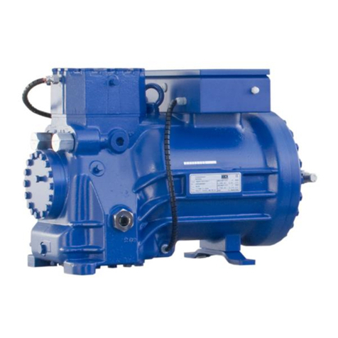
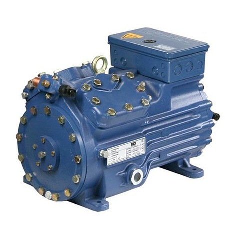
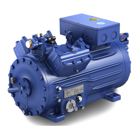
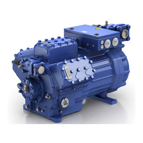
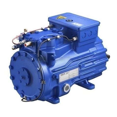
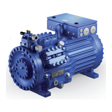
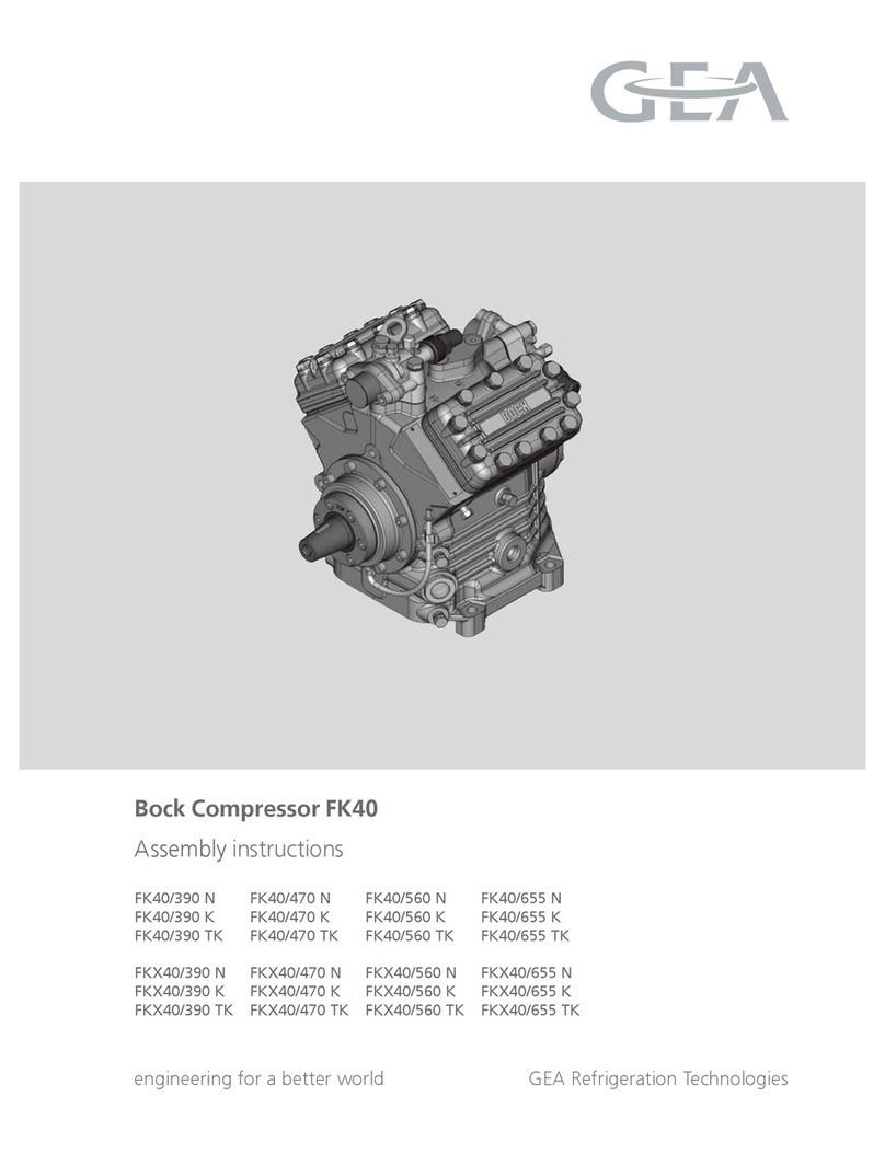
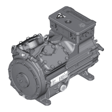
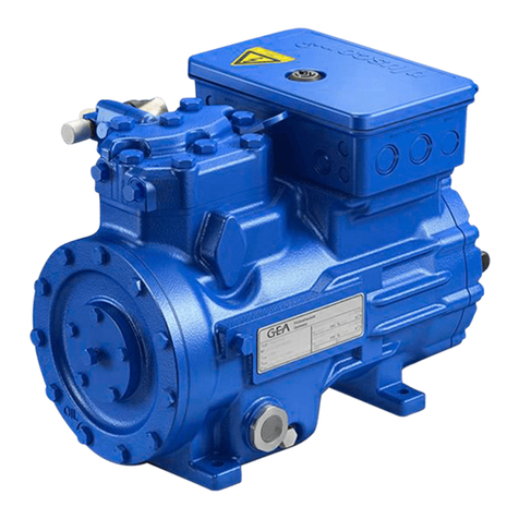
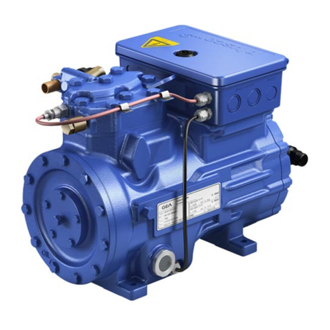
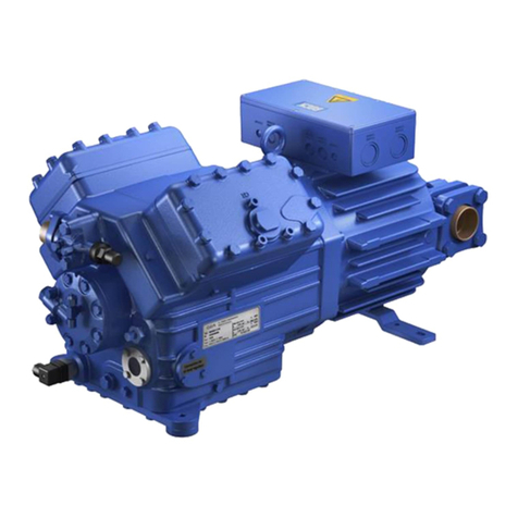
GEA HGX5/725-4 R134a User manual

D
GB
F
E
1
96180-09.2013-DGbFEI
engineering for a better world GEA Refrigeration Technologies
Bock Compressor HGX5 R134a
Assembly instructions
HGX5/725-4 R134a
HGX5/830-4 R134a
HGX5/945-4 R134a
1
2
3
4
5
6
7
8
9
10
1 112
13

2
D
GB
F
E
96180-09.2013-DGbFEI
1 Safety 4
1.1 Identicationofsafetyinstructions
1.2 Qualicationsrequiredofpersonnel
1.3 Generalsafetyinstructions
1.4 Intendeduse
2 Product description 6
2.1 Shortdescription
2.2 Nameplate
2.3 Typekey
3 Areas of application 8
3.1 Refrigerants
3.2 Oilcharge
3.3 Limitsofapplication
4Compressor assembly 10
4.1 Settingup
4.2 Pipeconnections
4.3 Pipes
4.4 Layingsuctionandpressurelines
4.5 Operatingtheshut-offvalves
4.6 Operatingmodeofthelockableserviceconnections
5 Electrical connection 13
5.1 Informationforcontactorandmotorcontactorselection
5.2 Standardmotor,designfordirectorpartwindingstart
5.3 Basiccircuitdiagramforpartwindingstartwithstandardmotor
5.4 Specialmotor:designfordirectorstar-deltastart
5.5 Basiccircuitdiagramforstar-deltastartwithspecialmotor
5.6 ElectronictriggerunitMP10
5.7 ConnectingthetriggerunitMP10
5.8 FunctionaltestofthetriggerunitMP10
5.9 Oilsumpheater(accessories)
6 Commissioning 23
6.1 Preparationsforstart-up
6.2 Pressurestrengthtest
6.3 Leaktest
6.4 Evacuation
6.5 Refrigerantcharge
6.6 Start-up
6.7 Avoidingslugging
6.8 Connectionofoillevelregulator
7 Maintenance 25
7.1 Preparation
7.2 Worktobecarriedout
7.3 Sparepartsrecommendation
7.4 Accessories
7.5 Extractfromthelubricantstable
7.6 Decommissioning
8 Technical data 27
9 Dimensions and connections 28
10 Declaration of conformity and installation 30
11 Service 31
About these instructions
Readtheseinstructionsbeforeassemblyandbeforeusingthecompressor.Thiswillavoidmisunder-
standings andpreventdamage.Improperassemblyanduseofthecompressorcanresultinserious
orfatalinjury.
Observethesafetyinstructionscontainedintheseinstructions.
Theseinstructionsmustbepassedontotheendcustomeralongwiththeunitinwhichthecompres-
sorisinstalled.
GEABockGmbH
72636Frickenhausen
GEABockGmbH
Benzstraße7
72636Frickenhausen
Germany
Telephone+49702294540
Fax +4970229454137
www.bock.de
Manufacturer
Contact

D
GB
F
E
3
96180-09.2013-DGbFEI
Contents Page
1 Safety 4
1.1 Identicationofsafetyinstructions
1.2 Qualicationsrequiredofpersonnel
1.3 Generalsafetyinstructions
1.4 Intendeduse
2 Product description 6
2.1 Shortdescription
2.2 Nameplate
2.3 Typekey
3 Areas of application 8
3.1 Refrigerants
3.2 Oilcharge
3.3 Limitsofapplication
4Compressor assembly 10
4.1 Settingup
4.2 Pipeconnections
4.3 Pipes
4.4 Layingsuctionandpressurelines
4.5 Operatingtheshut-offvalves
4.6 Operatingmodeofthelockableserviceconnections
5 Electrical connection 13
5.1 Informationforcontactorandmotorcontactorselection
5.2 Standardmotor,designfordirectorpartwindingstart
5.3 Basiccircuitdiagramforpartwindingstartwithstandardmotor
5.4 Specialmotor:designfordirectorstar-deltastart
5.5 Basiccircuitdiagramforstar-deltastartwithspecialmotor
5.6 ElectronictriggerunitMP10
5.7 ConnectingthetriggerunitMP10
5.8 FunctionaltestofthetriggerunitMP10
5.9 Oilsumpheater(accessories)
6 Commissioning 23
6.1 Preparationsforstart-up
6.2 Pressurestrengthtest
6.3 Leaktest
6.4 Evacuation
6.5 Refrigerantcharge
6.6 Start-up
6.7 Avoidingslugging
6.8 Connectionofoillevelregulator
7 Maintenance 25
7.1 Preparation
7.2 Worktobecarriedout
7.3 Sparepartsrecommendation
7.4 Accessories
7.5 Extractfromthelubricantstable
7.6 Decommissioning
8 Technical data 27
9 Dimensions and connections 28
10 Declaration of conformity and installation 30
11 Service 31

4
D
GB
F
E
96180-09.2013-DGbFEI
1|Safety
1.2 Qualicationsrequiredofpersonnel
1.3 General safety instructions
WARNING! Inadequately qualied personnel poses the risk of accidents, the
consequence being serious or fatal injury. Work on compressors
mustthereforeonlybeperformedbypersonnelwiththequalica-
tions listed below:
•For example, a refrigeration technician, refrigeration mechatron-
icsengineer.Aswellasprofessionswithcomparabletraining,which
enablepersonneltoassemble,install,maintainandrepairrefrigeration
andair-conditioningsystems.Personnelmustbecapableofassessing
theworktobecarriedoutandrecognisinganypotentialdangers.
WARNING! •Refrigerating compressors are pressurised machines and
thereforerequireparticularcautionandcareinhandling.
•Risk of burns! Depending on the operating conditions, surface
temperatures of over 60 °C on the pressure side or below 0 °C on
the suction side can be reached.
•The maximum permissible overpressure must not be exceeded,
even for testing purposes.
1.1 Identicationofsafetyinstructions:
DANGER! Indicatesadangeroussituationwhich,ifnot
avoided,willcauseimmediatefatalorseriousinjury.
WARNING!
Indicatesadangeroussituationwhich,ifnot
avoided,maycausefatalorseriousinjury.
CAUTION!
Indicatesadangeroussituationwhich,ifnot
avoided,maycausefairlysevereorminorinjury.
ATTENTION! Indicatesasituationwhich,ifnot
avoided,maycausepropertydamage.
INFO! Importantinformationortipsonsimplifyingwork.

D
GB
F
E
5
96180-09.2013-DGbFEI
1|Safety
TheseassemblyinstructionsdescribethestandardversionoftheHGX5R134amanufacturedby
Bock.Thecompressorisintendedforuseinrefrigerationsystemsincompliancewiththelimitsof
application.Onlytherefrigerantspeciedintheseinstructionsmaybeused.
Any other use of the compressor is prohibited!
TheBockrefrigeratingcompressornamedinthetitleisintendedforinstallinginamachine(within
theEUaccordingtotheEUDirectives2006/42/ECMachineryDirective,97/23/ECPressureEquipment
Directiveand2006/95/EC–LowVoltageDirective).
Commissioningisonlypermissibleifthe compressorhas beeninstalled inaccordance withthese
assembly instructions and the entire system into which it is integrated has been inspected and
approvedinaccordancewithlegalregulations.
1.4 Intended use
WARNING! The compressor may not be used in potentially
explosive environments!

6
D
GB
F
E
96180-09.2013-DGbFEI
2|Product description
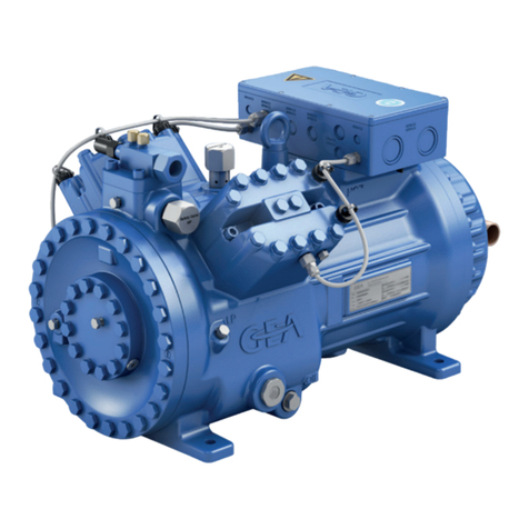
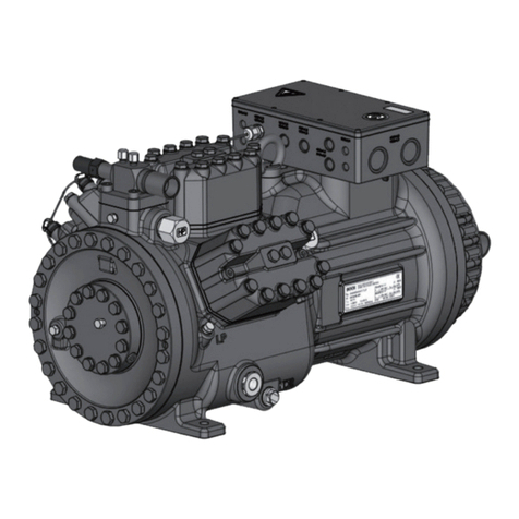
• Semi-hermeticfour-cylinderreciprocatingcompressorwithsuction-gascooleddrivemotor.
• Flange-mounteddrivemotoronthecompressorcase.
• Applicationrange:normalrefrigeratingandair-conditioningwithR134a.
Fig.1
2.1 Short description
DimensionandconnectionvaluescanbefoundinChapter9
Nameplate
Valveplate
Cylindercover
Terminalbox
Transporteyelet
Discharge
shut-offvalve
Oilpump
Suctionshut-
offvalve
Oilsightglass
Drivesection
Motorsection

D
GB
F
E
7
96180-09.2013-DGbFEI
2|Product description
/
HG 5945-4
X
Fig.2
2.2 Name plate (example)
2.3 Typekey (example)
¹)HG-HermeticGas-cooled(suctiongas-cooled)
²)X -Esteroilcharge
1
2
3
4
5
6
7
8
9
10
11
12
13
R134a
HGX5/945-4 R134a
AS12345-001
SE 55
33 A
110 A 141 A
Version
Numberofpoles
Sweptvolume
Size
Oilcharge²)
Series¹)
1 Typedesignation 6 Voltage,circuit,frequency
2 Machinenumber 7 Nominalrotationspeed
3 maximumoperatingcurrent 8 Displacement
4 Startingcurrent(rotorblocked) 9 Voltage,circuit,frequency
Y:Partwinding1 10 Nominalrotationspeed
YY:Partwindings1and2 11 Displacement
5 ND(LP):
max.admissibleoperating
12 Oiltypelledatthefactory
pressur
e (g)Lowpressureside 13 Terminalboxprotectiontype
HD(HP):
max.admissibleoperating
Electrical accessories can change
pressur
e(g)Highpressureside the IP protection class!
Observe the limits of application
diagrams!
50 Hz
}
60 Hz
}
GEA Bock GmbH
72636 Frickenhausen, Germany

8
D
GB
F
E
96180-09.2013-DGbFEI
3|Areas of application
Thecompressorsarelledatthefactorywiththefollowingoiltype:
FUCHSRenisoTritonSE55
Compressorswithesteroilcharge(FUCHSRenisoTritonSE55)aremarkedwithanXinthetype
designation(e.g.HGX5/945-4R134a).
3.1 Refrigerants
• HFKW/HFC: R134a
3.2 Oil charge
ATTENTION! Compressor operation is possible within the operating limits
shown in the diagrams. Please note the signicance
of the shaded areas. Thresholds should not be selected as design
or continuous operation points.
- Max. permissible discharge end temperature 140 °C
-Max.permissibleswitchingfrequency12x/h.
- A minimum running time of 3 min. steady-state condition
(continuous operation) must be achieved.
For operation with supplementary cooling:
- Use only oils with high thermal stability.
- Avoid continuous operation near the threshold.
For operation with capacity regulator:
- The suction gas superheat temperature may need to be reduced
or set individually when operating near to the threshold.
Foroperationwithfrequencyconverter:
- The maximum current and power consumption must not be
exceeded. Inthecaseofoperationabovethemainsfrequency,
the application limit can therefore be limited.
When operating in the vacuum range, there is a danger of air
enteringonthesuctionside.Thiscancausechemicalreactions,
a pressure rise in the condenser and an elevated compressed-gas
temperature. Prevent the ingress of air at all costs!
3.3 Limits of application
INFO! Forrefilling,werecommendtheaboveoiltypes.
Alternatives: seelubricantstable,Chapter7.5.
The oil level must be in the visible
part of the sight glass; damage
to the compressor is possible if
overfilled or underfilled!
ATTENTION!
Fig.3
max.oillevel
min.oillevel
D
GB
F
E
9
96180-09.2013-DGbFEI
3|Areas of application
Design for other
areasonrequest
Unlimitedapplicationrange
Supplementarycoolingor
reducedsuctiongastemperature
R134a
Fig.4
Evaporationtemperature(°C)
Condensingtemperature(°C)
Suctiongassuperheat(K)
Suctiongastemperature(°C)
Max. permissible operating
pressure (LP/HP)1): 19/28 bar
1) LP=Lowpressure
HP=Highpressure

10
D
GB
F
E
96180-09.2013-DGbFEI
?
4|Compressor assembly
4.1 Setting up
Setuponanevensurfaceorframewithsufcientload-
bearingcapacity.
Singlecompressorpreferablyonvibrationdamper.
Duplexandparallelcircuitsalwaysrigid.
Usetransporteyelet.
Donotliftmanually!
Useliftinggear!
Provideadequateclearanceformaintenancework.
Ensureadequatecompressorventilation.
Donotuseinacorrosive,dusty,dampatmosphereora
combustibleenvironment.
Fig.5
Fig.6
Fig.7
Fig.8
ATTENTION! Superheating can damage the valve.
Remove the pipe supports from the valve for soldering.
Only solder using inert gas to inhibit oxidation products (scale).
4.2 Pipe connections
The pipe connectionshavegraduatedinsidediameterssothatpipeswith
standartmillimetreandinchdimensionscanbeused.
Theconnectiondiametersoftheshut-offvalvesareratedformaximum
compressoroutput.Theactualrequiredpipecrosssectionmustbe
matched to the output. The same applies for non-return valves.
Fig.9:graduated
internaldiameter
F
E
D
C
B
A
1
2
3
4
F
E
D
C
4
3
2
1
A
B
Tol.-Ang. DIN ISO 2768-mK
Ra Rz
Maß
Passung
Freigabe
Alternativbezug:
Baumustergeprüft
Teil inaktiv
Lieferantenzeichnung
-
-
K.-Auftrag:
PL:
Zeichnung ungültig
Entwicklungsstand
Teil keine Serie
120
400
±0.5
über 0.5
bis 6
Benzstraße 7 - 72636 Frickenhausen - Germany - www.bock.de
-
-
Unbemaßte Radien:
-
Diese Zeichnung ist unser Eigentum!
Sie darf ohne unsere Genehmigung weder nach-
gebildet, vervielfältigt, oder Dritten Personen zu-
gänglich gemacht werden. Der Nachbau nach
dieser Zeichnung, oder an Hand der nach dieser
Zeichnung hergestellten Gegenstände durch den
Abnehmer oder Dritte ist nicht gestattet.
Wir behalten uns alle Rechte, gemäß DIN ISO 16016
an dieser Zeichnung vor.
Bearb.
Datum
Änderungs-Nr.
Werkstoff:
Ausgangsteil, bzw. Rohteil:
--
Gepr.
Name
Datum
19.04.
Werkstückkanten
DIN ISO 13715
Ersatz für:
Ersetzt durch:
Erstellt
2010
Geprüft
-
Kurz
Zone
1/x
Oberflächenbehandlung / Härte:
-
Blatt:
Änderungsbeschreibung
400
Benennung:
±0.8
1000
30
6
-
±0.3
120
30
±0.2
Zeichn.-Nr. Teile-Nr.
Oberflächenangaben ISO 1302
x.xxxx-xxxxx.x
Zust.
Gußtoleranzen:
Gewicht: (kg)
±0.1
Maßstab:
1:1
Wasserwaage
für Indesign
Der Lieferant muß sicherstellen, dass die Ware in
einwandfreiem Zustand angeliefert wird (Korrosions-
schutz, Verpackung für sicheren Transport).
Rz 25
Rz 160
s
25
z
y
x
w
u
t
0,05
Rz 1,6
0,3
0,7
1,6
2
Rz 16
6,3
Rz 63
Rz 6,3
Rz 12,5
F:\user\kurz\3D Sachen\3D Teile\Zeichnungen\Wasserwaage
INFO! Newcompressorsarefactory-lledwithinertgas(3barnitrogen).
Leave this service charge in the compressor for as long as possible
and prevent the ingress of air.
Check the compressor for transport damage before starting any
work.

D
GB
F
E
11
96180-09.2013-DGbFEI
4.4 Laying suction and pressure lines
INFO! Proper layout of the suction and pressure lines directly after the
compressor is integral to the smooth running and vibration behaviour
of the system.
ATTENTION! Improperly installed pipes cancause cracks and tears whichcan
resultinalossofrefrigerant,
4|Compressor assembly
4.3 Pipes
Pipesandsystemcomponentsmustbecleananddryinsideandfreeofscale,swarfandlayersof
rustandphosphate.Onlyuseair-tightparts.
Lay pipes correctly. Suitable vibration compensators must be provided to prevent pipes being
crackedandbrokenbyseverevibrations.
Ensureaproperoilreturn.
Keeppressurelossestoanabsoluteminimum.
A rule of thumb:
Alwayslaytherstpipesectionstartingfromtheshut-offvalvedownwards and
parallel to the drive shaft.
Fig.10
As short as
possible
Rigid
fixed point
1
2
3
4
5
6
7
8
9
10
1 1 12
13
1
2
3
4
5
6
7
8
9
10
1 1 12
13

12
D
GB
F
E
96180-09.2013-DGbFEI
4|Compressor assembly
4.5 Operating the shut-off valves
Beforeopeningorclosingtheshut-offvalve,releasethevalvespindlesealbyapprox.¼ofaturn
counter-clockwise.
Afteractivatingtheshut-offvalve,re-tightentheadjustablevalvespindlesealclockwise.
Pipeconnection
Pipeconnection
4.6 Operatingmodeofthelockableserviceconnections
Fig.13
Opening the shut-off valve:
Spindle:turntotheleft(counter-clockwise)asfarasitwillgo.
—>Shut-offvalvecompletelyopened/serviceconnectionclosed.
Theconnectionwhichcannotbeshutoffisintendedforsafetydevices.
Fig.14
Opening the service connection
Spindle:Turn½-1turnclockwise.
—>Serviceconnectionopened/shut-offvalveopened.
Theconnectionwhichcannotbeshutoffisintendedforsafetydevices.
Serviceconnec-
tionclosed
Connection
blocked
Spindle
Connectioncannotbe
shutoff
Connectioncannotbe
shutoff
Serviceconnec-
tionopened
Spindle Connection
open
Compressor
Compressor
Fig.11 Fig.12
Valve spindle seal
Release
Tighten

D
GB
F
E
13
96180-09.2013-DGbFEI
5|Electrical connection
5 Electrical connection
DANGER! Highvoltage!Riskofelectricshock!Onlycarryoutworkwhenthe
electrical system is disconnected from the power supply!
INFO! Connectthecompressormotorinaccordancewiththecircuitdiagram
(seeinsideofterminalbox).
Use suitable cable entry point of the correct protection type
(see name plate) for routing cables into the terminal box.
Insert the strain reliefs and prevent chafe marks on the cables.
Comparethevoltageandfrequencyvalueswiththedataforthemains
powersupply.
Only connect the motor if these values are the same.
5.2 Standardmotor,designfordirectorpartwindingstart
Designationonthenameplate Stickerontheterminalbox
Y/YY
Compressorswiththismarkingaresuitablefordirectorpartialwindingstart.Themotorwindingis
subdividedintotwoparts:Partialwinding1=66%andpartwinding2=33%.Thiswindingdivision
reducesthestart-upcurrentneededforapartwindingstarttoapprox.65%ofthatforadirectstart.
INFO! A mechanical unloaded start with bypass solenoid valve is
notrequired.
5.1 Information for contactor and motor contactor selection
Allprotectionequipment,switchingandmonitoringdevicesmustcomplywiththelocalsafetyregula-
tionsandestablishedspecications(e.g.VDE)andregulationsaswellasthemanufacturer’sspecica-
tions.Motorprotectionswitchisrequired!Motorcontactors,feedlines,fusesandmotorprotection
switchesmustberatedaccordingtothemaximumoperatingcurrent(seenameplate).
Usethefollowingoverloadprotectiondevice:
Acurrent-dependenttime-delayedoverloadprotectiondeviceformonitoringofallthreephases,not
sethigherthantheratedcurrentofthemachine,whichmustrespondat1.2timesthesetcurrent
within2hoursandmustnothaverespondedat1.05timesthesetcurrentwithin2hours,oranother
comparabledevice.

14
D
GB
F
E
96180-09.2013-DGbFEI
5.3 Basic circuit diagram for part winding start with standard motor
Fig.15
nderung
0
Datum Name
Datum
Bearb.
Gepr.
Norm
1
20.Feb.2009
Kelich
09.M„r.2010
Urspr.
2
Ers..
3
Ers.d.
4
PWMP10
5 6 7
BKMPRESSRS
8
=
+
9
Bl.
1
Bl.
1
XSS
Q1
L1 L2 L3 N PE
AnschluastenVerdichter
I=66%
F1.1
K1
1
2
1
3
4
2
5
6
3
1U1
1V1
1W1
PE
M
Y/YY
M1
R1
2U1
2V1
2W1
I=33%
F1.2
K2
1
2
4
3
4
5
5
6
6
X1 L1 L1 N N 43 43 11 12 14
L S M
X2 1 2 3 4 5 6
7
F1.1
F1.2
8
R2
4A
F2
S1
9 10
MP10
11
F5
K1
12
T2
13
N
Pl
14
L
15
M
16
S
P>
F3
17 18 19
K1
P
F4
20
K1
K1T
K2
21 22
K1T
P<
B1
23 24
K1
25
E1
26
L1.1
L2.1
L3.1
L1.2
N
PE
R1 Coldconductor(PTCsensor)motorwinding
R2 Thermalprotectionthermostat(PTCsensor)
F1.1/1.2
2motorprotectionswitches(66%/33%ofIAtotal)
F2 Controlpowercircuitfuse
F3 Highpressuresafetymonitor
F4 Safetychain(high/lowpressuremonitoring)
F5 Oildifferentialpressuremonitor
B1 Releaseswitch(thermostat)
Compressorterminalbox

D
GB
F
E
15
96180-09.2013-DGbFEI
nderung
0
Datum Name
Datum
Bearb.
Gepr.
Norm
1
20.Feb.2009
Kelich
09.M„r.2010
Urspr.
2
Ers..
3
Ers.d.
4
PWMP10
5 6 7
BKMPRESSRS
8
=
+
9
Bl.
1
Bl.
1
XSS
Q1
L1 L2 L3 N PE
AnschluastenVerdichter
I=66%
F1.1
K1
1
2
1
3
4
2
5
6
3
1U1
1V1
1W1
PE
M
Y/YY
M1
R1
2U1
2V1
2W1
I=33%
F1.2
K2
1
2
4
3
4
5
5
6
6
X1 L1 L1 N N 43 43 11 12 14
L S M
X2 1 2 3 4 5 6
7
F1.1
F1.2
8
R2
4A
F2
S1
9 10
MP10
11
F5
K1
12
T2
13
N
Pl
14
L
15
M
16
S
P>
F3
17 18 19
K1
P
F4
20
K1
K1T
K2
21 22
K1T
P<
B1
23 24
K1
25
E1
26
L1.1
L2.1
L3.1
L1.2
N
PE
Q1 Mainswitch
M1 Compressormotor
K1 Mainscontactor(partwinding1)
K2 Mainscontactor(partwinding2)
K1T Delayrelaymax.1s
S1 Controlvoltageswitch
E1 Oilsumpheater

16
D
GB
F
E
96180-09.2013-DGbFEI
5|Electrical connection
ATTENTION! Failure to do this results in opposed rotary elds and results in
damage to the motor. After the motor starts up via partial winding
1,partialwinding2mustbeswitchedonafteramaximumdelayof
one second . Failure to comply can adversely affect the service life
of the motor.
Themotoriswiredfordirectstart(YY)atthefactory.ForpartwindingstartY/YY,thebridgesmustbe
removedandthemotorfeedlineconnectedaccordingtothecircuitdiagram:
400 V
Direktstart YY Teilwicklungsstart Y/YY
1V1 1W11U1
2W12V12U1
L3L2L1 L3L2L1
L3L2L1
1V1 1W11U1
2W12V12U1
400 V
Direct start YY
Part winding start Y/YY
400 V
Direktstart YY Teilwicklungsstart Y/YY
1V1 1W11U1
2W12V12U1
L3L2L1 L3L2L1
L3L2L1
1V1 1W11U1
2W12V12U1

D
GB
F
E
17
96180-09.2013-DGbFEI
5|Electrical connection
5.4 Special motor: design for direct or star-delta start
Amechanicalunloadedstartwithbypasssolenoidvalve(accessories)isrequiredforthe
star-delta start.
Designationonthenameplate Stickerontheterminalbox
∆/ Y
Star-delta start-up is only possible for 230 V power supply. Example:
230 V ∆
Direct start Star-delta start
400 V Y
Direct start only
5.4 Sondermotor: Ausführung für Direkt- oder Stern-Dreieck-Anlauf
Für den Stern-Dreieck-Anlauf ist eine mechanische Anlaufentlastung mit Bypass-Magnetventil
(Zubehör) erforderlich.
Bezeichnung auf dem Typschild Aufkleber auf Klemmenkasten
∆/ Y
Stern-Dreieck-Anlauf ist nur im Spannungsbereich ∆(230 V) möglich. Beispiel:
230 V ∆
Direktstart Stern-Dreieck-Start
L3L1
V1 W1
U1
V2
U2
W2
L1 L2 L3
L2
V1 W1
U1
V2
U2
W2
L3L2L1
400 V Y
nur Direktstart
V1 W1U1
V2U2W2
L1 L2 L3

18
D
GB
F
E
96180-09.2013-DGbFEI
5.5 Basic circuit diagram for star-delta start with special motor
Fig.16
nderung
0
Datum Name
Datum
Bearb.
Gepr.
Norm
1
20.Feb.2009
Kelich
09.M„r.2010
Urspr.
2
Ers..
3
Ers.d.
4
D/S
MP10
5 6 7
BKMPRESSRS
8
=
+
9
Bl.
1
Bl.
1
XSS
Q1
L1 L2 L3 N PE
F1.1
K1
1
2
F1.2
1
AnschluastenVerdichter
3
4
2
5
6
3 PE
U1
V1
W1
M
3
~
M1
Y
K3
1
2
3
4
R1
5
6
W2
U2
V2
D
K2
1
2
4
3
4
5
5
6
6
X1 L1 L1 N N 43 43 11 12 14
L S M
X2 1 2 3 4 5 6
7
F1.1
F1.2
8
R2
4A
F2
S1
9 10
MP10
11
F5
K1
12
T2
13
N
Pl
14
L
15
M
16
S
K1
K1
K3
P>
F3
K4T
K3
K2
17
K4T
K2
K3
18 19
K4T
P
F4
20
K5T
AL
21 22
K5T
P<
B1
23 24
K1
25
E1
26
L1.1
L2.1
L3.1
L1.2
N
PE
Compressorterminalbox
R1 Coldconductor(PTCsensor)motorwinding
R2 Thermalprotectionthermostat(PTCsensor)
F1.1/1.2
2motorprotectionswitches
F2 Controlpowercircuitfuse
F3 Highpressuresafetymonitor
F4 Safetychain(high/lowpressuremonitoring)
F5 Oildifferentialpressuremonitor
B1 Enablingswitch(thermostat)
Q1 Mainswitch

D
GB
F
E
19
96180-09.2013-DGbFEI
nderung
0
Datum Name
Datum
Bearb.
Gepr.
Norm
1
20.Feb.2009
Kelich
09.M„r.2010
Urspr.
2
Ers..
3
Ers.d.
4
D/S
MP10
5 6 7
BKMPRESSRS
8
=
+
9
Bl.
1
Bl.
1
XSS
Q1
L1 L2 L3 N PE
F1.1
K1
1
2
F1.2
1
AnschluastenVerdichter
3
4
2
5
6
3 PE
U1
V1
W1
M
3
~
M1
Y
K3
1
2
3
4
R1
5
6
W2
U2
V2
D
K2
1
2
4
3
4
5
5
6
6
X1 L1 L1 N N 43 43 11 12 14
L S M
X2 1 2 3 4 5 6
7
F1.1
F1.2
8
R2
4A
F2
S1
9 10
MP10
11
F5
K1
12
T2
13
N
Pl
14
L
15
M
16
S
K1
K1
K3
P>
F3
K4T
K3
K2
17
K4T
K2
K3
18 19
K4T
P
F4
20
K5T
AL
21 22
K5T
P<
B1
23 24
K1
25
E1
26
L1.1
L2.1
L3.1
L1.2
N
PE
M1 Compressormotor
K1 Mainscontactor
K2 ∆-contactor
K3 Y-contactor
K4T DelayrelayS/Dchangeover
K5T Delayrelay,startunloader
S1 Controlvoltageswitch
AL Startunloader
E1 Oilsumpheater

20
D
GB
F
E
96180-09.2013-DGbFEI
5|Electrical connection
ATTENTION!
Terminals 1 - 6 on the trigger
unit MP 10 and terminals PTC
1 and PTC 2 on the compres-
sor terminal board must not
come into contact with mains
voltage. This would destroy the
trigger unit and PTC sensors.
The supply voltage at L1-N
(+/- for DC 24 V version) must
be identical to the voltage at
terminals11,12,14and43.
5.6 Electronic trigger unit MP 10
The compressor motor is tted with cold conductor temperature sensors (PTC) connected to the
electronictriggerunitMP10intheterminalbox.ReadinesstooperateissignalledbytheH3LED
(green)afterthepowersupplyisapplied.Inthecaseofexcesstemperatureinthemotorwinding,the
unitswitchesoffthecompressorandtheH1LEDlightsred.
Thehotgassideofthecompressorcanalsobeprotectedagainstovertemperatureusingathermal
protectionthermostat(accessory).TheH2LED(red)isprovidedfortheprotectionfunction.
The unit trips when an overload or inadmissible operating conditions occur. Find and remedy
the cause.
5.7 Connection of the tripping unit MP10
INFO! Connect the trigger unit MP10 in accordance with the circuit dia-
gram. Protect the trigger unit with a delayed-action fuse (F) of max.
4A.Inordertoguaranteetheprotectionfunction,installthetrigger
unitastherstelementinthecontrolpowercircuit.
Temperaturemonitoringconnections:
Motorwinding: Terminals1-2
Thermalprotectionthermostat: Terminals3-4
Restartprevention: Terminals5-6
INFO!
Theunithasarestartpreventiondevice.Afteryouhaverectiedthe
fault, either interrupt the mains voltage or acknowledge with the
external alarm reset switch S1 (see circuit diagram, Chapter 5.5).
ThisunlockstherestartpreventiondeviceandtheLEDsH1andH2
go out.
Fig.17
Terminalboard
This manual suits for next models
3
Table of contents
Other GEA Air Compressor manuals

GEA
GEA HG88e series User manual

GEA
GEA Bock HGX46 CO2 T Series User manual

GEA
GEA Grasso RC9 Series User manual

GEA
GEA HG12P User manual

GEA
GEA Bock HG8 Series User manual

GEA
GEA HG6/1080-4 User manual

GEA
GEA Grasso M-Series User manual

GEA
GEA HG34P/e User manual

GEA
GEA HG22P Series User manual

GEA
GEA Bock HGX2 CO2 T Series User manual