10
D
GB
F
E
96416-08.2020-DGbFEIRu
ATTENTION The oil level must be in the
visiblepartofthesightglass;
damage to the compressor
is possible if overfilled or
underfilled!
4 |Areas of application
Thecompressorsarelledatthefactorywiththefollowingoiltype:
-fürR134a,R404A/R507,R407C,R407F FUCHSRenisoTritonSE55
-fürR22 FUCHSRenisoSP46
Compressorswithesteroilcharge(FUCHSRenisoTritonSE55)aremarkedwithanXinthetype
designation(e.g.HGX44e/770-4).
4.1 Refrigerants
• HFKW/HFC: R134a,R404A/R507,R407C,R407F
• (H)FCKW/(H)CFC: R22
4.2 Oilcharge
INFO Forrefilling,werecommendtheaboveoiltypes.
Alternatives:seelubricantstable,Chapter 7.5
ATTENTION Compressoroperationispossiblewithintheoperatinglimits.
ThesecanbefoundinBockcompressorselectiontool(VAP)
undervap.bock.de.Observetheinformationgiventhere.
-Permissibleambienttemperature(-20°C)-(+60°C)
-Max.permissibledischargeendtemperature140°C.
-Max.permissibleswitchingfrequency12x/h.
-Aminimumrunningtimeof3min.steady-statecondition
(continuousoperation)mustbeachieved.
Foroperationwithsupplementarycooling:
-Useonlyoilswithhighthermalstability.
-Avoidcontinuousoperationnearthethreshold.
Foroperationwithcapacityregulator:
- Continuousoperation,whenthecapacityregulatorisactivated,
isnotpermissibleandcancausedamagetothecompressor.
-Thesuctiongassuperheattemperaturemayneedtobereduced
orsetindividuallywhenoperatingneartothethreshold.
- Whenthecapacityregulatorisactivated,thegasvelocityinthe
systemcannotundercertaincircumstancesensurethatsuf-
cientoilistransportedbacktothecompressor.
Foroperationwithfrequencyconverter:
- The maximum current and power consumption must not be
exceeded.Inthecaseofoperationabovethemainsfrequency,the
applicationlimitcanthereforebelimited.
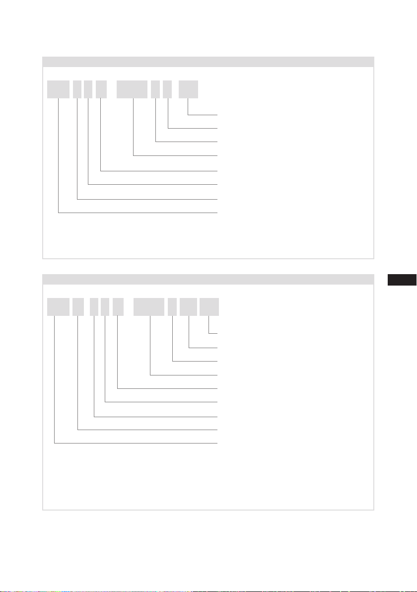
4.3 Limitsofapplication
max.
min.
oillevel
Fig.4Fig.4Fig.4
HG44e
1,6Ltr.
HG56e
1,4Ltr.
~
~
~
~