8
D
GB
F
E
I
Ru
09971-06.2016-DGbFEIRu
INFO For refilling, we recommend the above oil types.
Alternatives: see lubricants table, Chapter 7.5
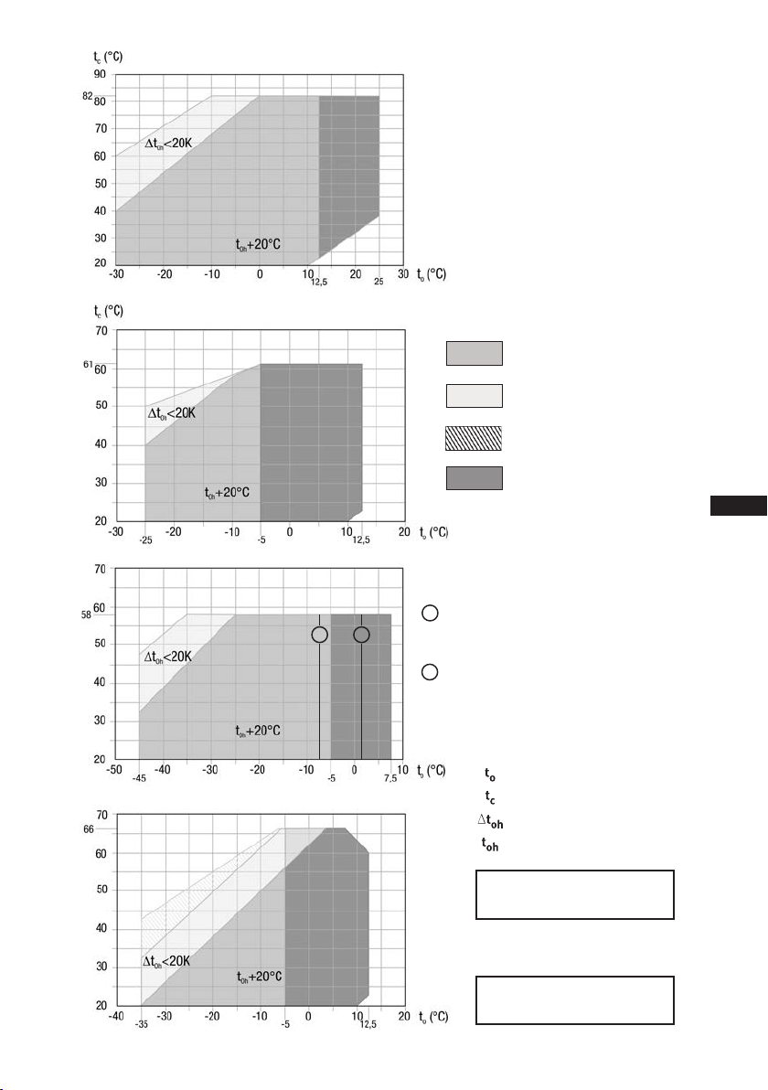
ATTENTION Compressor operation is possible within the operating limits
showninthediagrams.Pleasenotethesignicance
of the shaded areas. Thresholds should not be selected as
design or continuous operation points.
- Permissible ambient temperature (-20°C) - (+60°C)
- Max. permissible discharge end temperature 140°C.
-Max.permissibleswitchingfrequency12x/h.
- A minimum running time of 3 min. steady-state condition
(continuous operation) must be achieved.
For operation with supplementary cooling:
- Use only oils with high thermal stability.
- Avoid continuous operation near the threshold.
For operation with capacity regulator:
- Continuous operation, when the capacity regulator is activated,
is not permissible and can cause damage to the compressor.
- The suction gas superheat temperature may need to be reduced
or set individually when operating near to the threshold.
- When the capacity regulator is activated, the gas velocity in the
systemcannotundercertaincircumstancesensurethatsuf-
cient oil is transported back to the compressor.
Foroperationwithfrequencyconverter:
- The maximum current and power consumption must not be
exceeded.Inthecaseofoperationabovethemainsfrequency,the
application limit can therefore be limited.
When operating in the vacuum range, there is a danger of air
entering on the suction side. This can cause chemical reactions,
a pressure rise in the condenser and an elevated compressed-gas
temperature. Prevent the ingress of air at all costs!
3.3 Limits of application
3|Areas of application
Thecompressorsarelledatthefactorywiththefollowingoiltype:
- for R134a, R404A/R507, R407C FUCHS Reniso Triton SE 55
- for R22 FUCHS Reniso SP 46
Compressors with ester oil charge (FUCHS Reniso Triton SE 55) are marked with an X in the type
designation (e.g. HGX6/1410-4).
3.1 Refrigerants
• HFKW / HFC: R134a, R404A/R507, R407C
• (H)FCKW / (H)CFC: R22
3.2 Oil charge
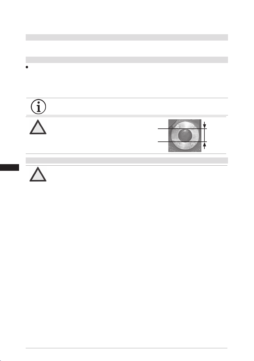
Fig. 4
max.
min.
2,0 Ltr.
oil level ~
~
ATTENTION The oil level must be in the
visible part of the sight glass;
damage to the compressor is
possible if overfilled or under-
filled!