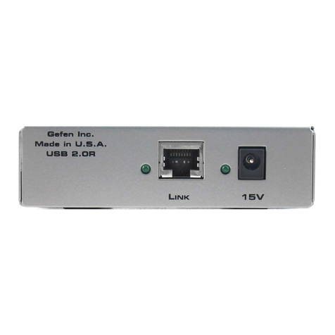
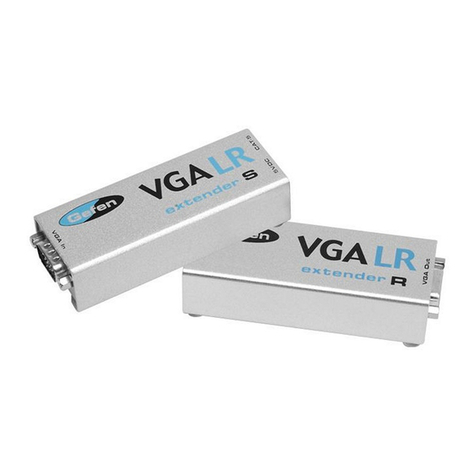
Gefen EXT-VGAAUD-CAT5-142 User manual
Other Gefen Extender manuals

Gefen
Gefen EXT-DVI-CAT5-4X User manual
Gefen
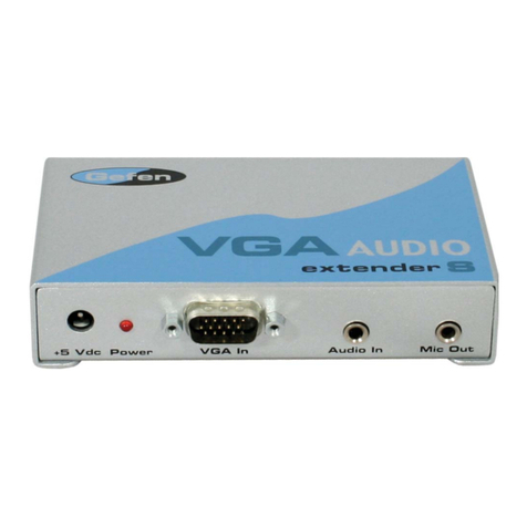
Gefen VGA-AUDIO-141 User manual

Gefen
Gefen CAT5-7000 User manual

Gefen
Gefen Audio Extender User manual

Gefen
Gefen VGARS232-141 User manual
Gefen
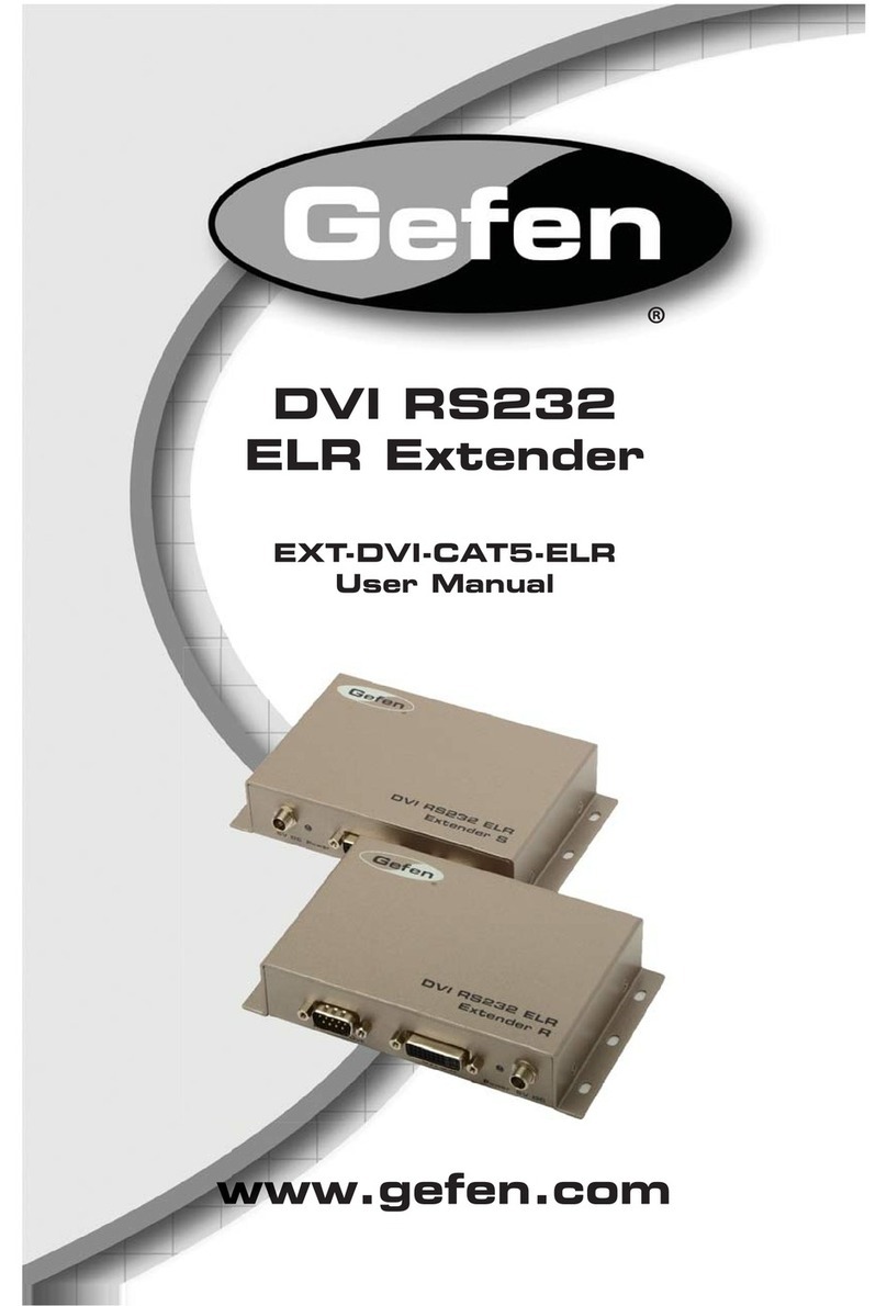
Gefen EXT-DVI-CAT5-ELR User manual

Gefen
Gefen CAT5-8000 User manual

Gefen
Gefen EXT-DVIKA-HBT2 User manual
Gefen
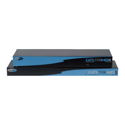
Gefen EXT-CAT5-5500HD User manual

Gefen
Gefen GTB-DVIKVM-ELR User manual

Gefen
Gefen GTV-WHDMI User manual

Gefen
Gefen EXT-HDMI-EDIDP User manual

Gefen
Gefen EXT-DVI-FM2500 User manual
Gefen
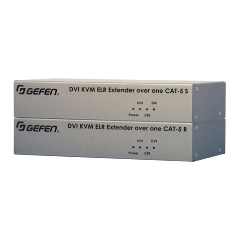
Gefen EXT-DVIKVM-ELR User manual

Gefen
Gefen EXT-HDMI1.3-CAT6-4X User manual

Gefen
Gefen USB-400 User manual

Gefen
Gefen EXT-HDTV-CAT5 User manual
Gefen
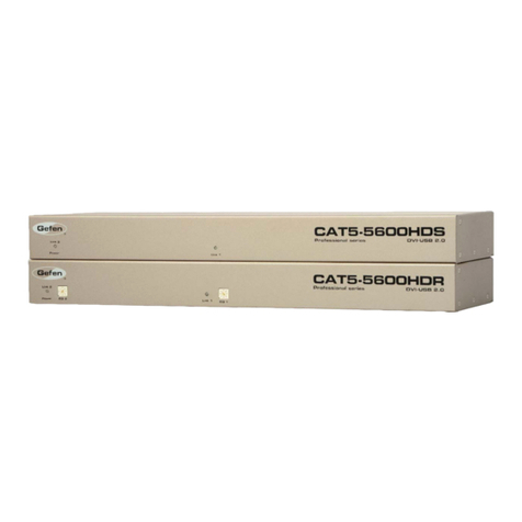
Gefen CAT5-5600HD User manual

Gefen
Gefen EXT-DIGAUD-141 User manual
Gefen
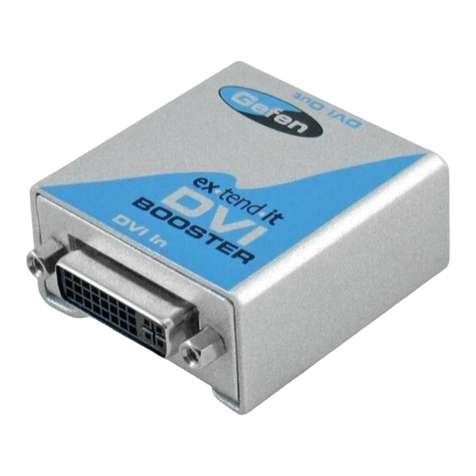
Gefen EXT-DVI-141B User manual
Popular Extender manuals by other brands

foxunhd
foxunhd SX-AEX01 operating instructions

TERK Technologies
TERK Technologies LFIRX2 owner's manual

Devolo
Devolo Audio Extender supplementary guide

Edimax
Edimax EW-7438RPn V2 instructions

Shinybow USA
Shinybow USA SB-6335T5 instruction manual

SECO-LARM
SECO-LARM ENFORCER EVT-PB1-V1TGQ installation manual


