SATEL ACX-201
be protected with a suitable fuse. It is recommended that the expander be
mounted as high as practicable. This will enable a better radio communication
range to be achieved, while avoiding the risk of the expander being accidentally
covered by personnel moving around the premises. Using the ARF-100 tester,
make sure that the level of radio signal will be suitable at the place where the
ACX-201 expander is to be installed. Select another place of installation, if
necessary.
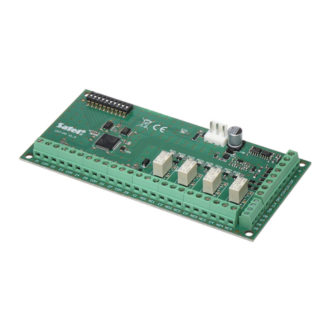
2. Install plugs for fastening the expander electronics board in the housing.
3. Pull all the necessary installation cables (for 230 V AC supply, connections
between hardwired devices and the expander, etc.) through the opening in the
rear panel of the housing.
4. Attach the housing to the wall.
5. Secure the expander board in the housing.
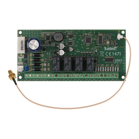
6. Attach the antenna to the housing and connect it to the onboard socket.
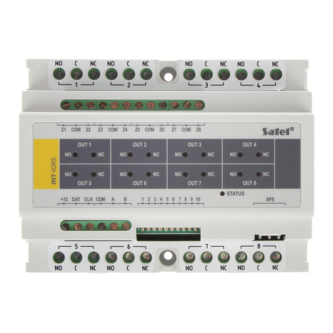
7. Connect all the required leads to the expander terminals.
8. Connect the mains supply cables to the 230 V AC transformer terminals. Connect
the ground cable to the terminal designated by the earth symbol , situated on
the rear panel of the metal housing.
9. Turn on 230 V AC supply. Measure the voltage across the battery leads (the
correct value is between 13.6 and 13.8 V DC) and check that all the consumers
are appropriately supplied.
10. Turn off 230 V AC supply.
11. Connect the battery. The expander will not start upon connecting the battery
alone.
Note: When the battery voltage drops below 11 V, the expander will send
information on the battery failure to the ACU-100 controller, and when the
voltage goes down to about 9.5 V the battery will be disconnected.
12. Turn on 230 V AC supply and add the ACX-201 expander to the wireless system
(see the ACU-100 controller user manual). A label with 7-digit serial number that
should be entered during registration of the expander in the system is provided on
the electronics board.
Note:Should a situation occur that the expander supply must be disconnected
completely, disconnect the mains first and the battery second. To reconnect
the power supply, do it in the reverse order (i.e. the battery first, and then the
230 V alternating voltage).
13. Close the housing.
14. Configure the expander zones to suit your requirements. For information about the
ACX-201 expander configuration, see the ACU-100 controller user manual.
3. Technical data
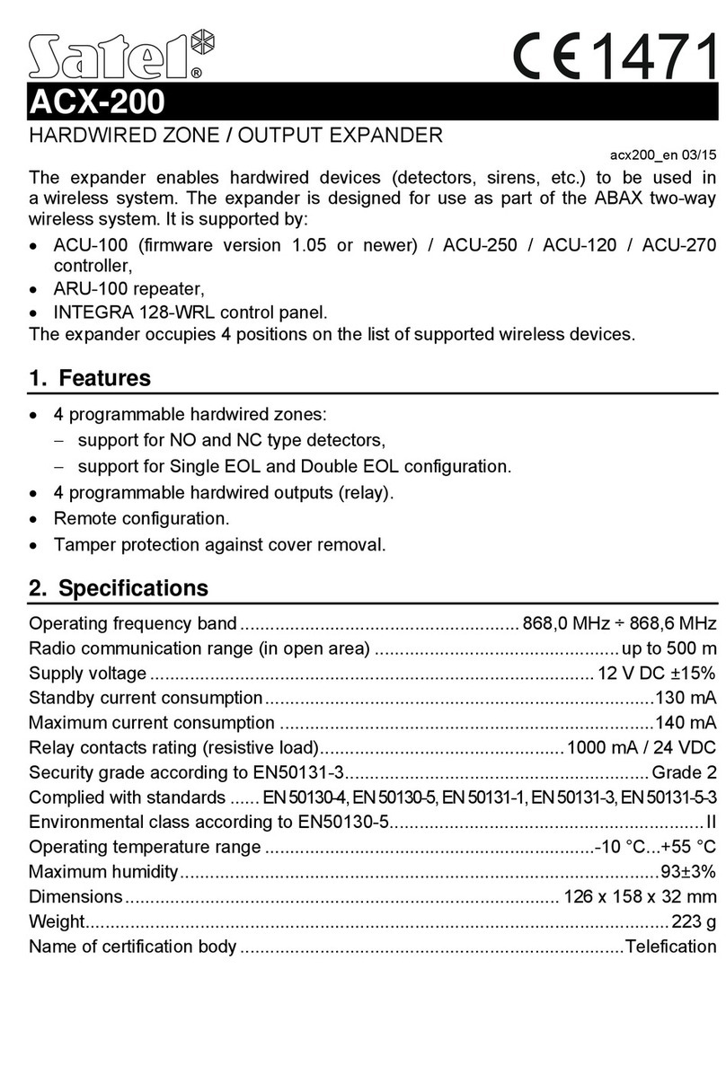
Working frequency band...........................................................868.0 MHz ÷ 868.6 MHz
Radio communication range (in open area) .................................................up to 500 m
Rated supply voltage............................................................................... 18 V AC ±10%
