manuals.online logo
Brands
  1. Home
  2. •
  3. Brands
  4. •
  5. Gemas
  6. •
  7. Swimming Pool Pump
  8. •
  9. Gemas RANGER User manual

Gemas RANGER User manual

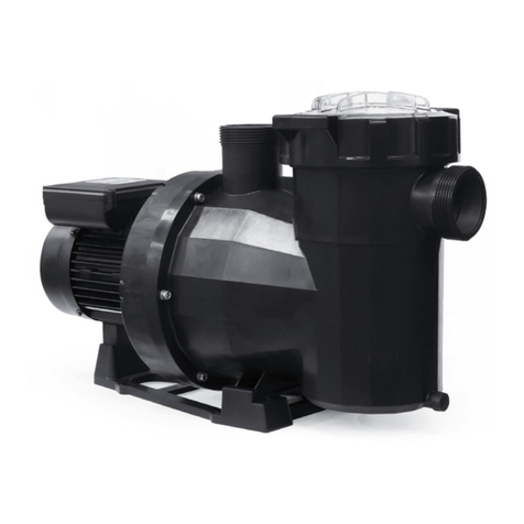
GEMAS RANGER PUMP
INSTRUCTION MANUAL
Pumps are complete with 5 wire cable for connection. Cable colours are shown on below chart with
RPM amounts.
Cables should be connected to dry contact. Contacts must be changed seperately. Otherwise speed
can not be adjusted.
PUMP CONTROLLER OPERATION GUIDE
Rev.1.2
The pump controller version 1.2 provides two pump operation modes of constant power control
and constant speed control with advanced sensorless sine wave vector control method.A four-
digits each with 7-segment led displays the motor speed, power percentage, and fault code
information
Default Settings:
Preset control mode
0 = constant power
1 = constant speed
Preset fixed speed
1= 2000 d/d
2= 2400 d/d
3= 2850 d/d
Preset fixed power or flow percentage
1= %60
2= %80
3= %100
Priming speed
Priming time
2850 rpm
5 minutes
Speed which can be set
1000-2850 rpm (in 50 rpm per step)
Priming time which can be set
0 - 10 minutes (in 1 minute per step)
(1) LED window: displays the current speed of
the motor, or error code message.
(2) "SET" button: used to enter the programming
mode or to reset the control.
(3) Button "1/ ▼": used to select the fixed low
speed or to decrease in the programming mode.
(4) Button "2/OK": used to select the fixed
medium speed or to confirm/save parameters in
the programming mode.
(5) Button "3/ ▲": used to select the fixed high
speed or to increase in the programming mode.
(6) Button "0": to stop the motor.
(7) Power light: illumines when power turns on.
(8) Error light: illumines when there is a fault.
Presetting the control mode and control signal source
Presetting the fixed speed in constant speed operation mode
In constant speed operation mode, press the button "1", "2" or "3" of the
fixed speed which is to be changed and the LED window displays the
current speed, then keep the "SET" button pressed for at least three
seconds until the speed displayed in the LED window begins to flash. Now
the speed can be changed with the buttons “▼▲”. Every time the button
“▼”or “▲”is pressed, the speed decreases or increases by 50 rpm. The
upper limit of the speed is 2850 rpm and the lower limit is 1000 rpm. To
save the set speed confirm with "OK" button. To cancel and return to the
original speed press the “SET” button.
The default setting is as follows:
1 = 2000 rpm
2 = 2400 rpm
3 = 2850 rpm
Keep the "SET" button be pressed when turning on the ac power supply
till the LED display shows "0" . The digit is for control mode setting.
The digits can be changed with the buttons “▼▲”. Press "OK" button to
save the settings, and the display shows "OFF".
Control mode code
0 = constant power
1 = constant speed
Presetting the fixed power in constant power operation mode
The power or flow is shown in percentage of the maximum power
rating or flow rating. In constant power operation mode or constant
flow operation mode, press the button "1", "2" or "3" of the fixed
value which is to be changed and the LED window displays the current
power percentage, then keep the "SET" button pressed for at least
three seconds until the speed displayed in the LED window begins to
flash. Now the power percentage can be changed with the buttons
“▼▲”. Every time the button “▼”or “▲”is pressed, the speed
decreases or increases by 1%. The upper limit of the speed is 100% and
the lower limit is 5%. To save the set power percentage confirm with
"OK" button. To cancel and return to the original speed press the “SET”
button.
The default setting of the power or flow percentage is as below:
1 = 60 %
2 = 80 %
3 = 100 %
Setting the priming parameters
The motor has to be stopped ("0" button) to program the priming
speed and time. Then press the "SET" button again for at least three
seconds until the speed displayed in the LED window begins to flash.
Now the speed can be set with which the motor is to start up during
the priming time. The speed can be changed with the buttons “▼▲”,
the upper limit of the priming speed is 2850 rpm and the lower limit is
1000 rpm. Press the button "OK to save the speed setting and enter
the phase for priming time setting, or press "SET" to cancel and return
to the previous mode. After the priming speed has been set, the
period of the priming time can be specified with regard to a range
from 0 to 10 minutes.
Stop operation
1. Button "0" is pressed;
2. stop signal is detected if wire control is selected
3. Fault occurred
If the pump is stopped normally as in the above case 1~3, the
"Power" LED flashes and the LED display shows "OFF", while the
LED shows an error code if the pump is stopped due to a fault.
When the power is turned on and the motor is at the standby
state, the LED display also shows “OFF” if there is no error, and the
power light flashes.
Start the pump
Manual operation
Press button "1", "2" or "3" to select the preset fixed speed or
preset fixed power.
If the pump starts from standby state, it starts up in priming mode
and subsequently runs with the selected fixed speed or fixed
power.
As long as the pump is in the priming phase, the light of the
selected speed or power flashes.
During running operation the pump will be accelerated or
decelerated to the selected fixed speed or fixed power directly,
without priming time.
Preset speed or power can be changed during running operation.
Please refer to “Presetting the fixed speed in constant speed
operation mode” for the change operation method.
Recover factory default settings
The motor can be reset to the state of factory delivery by
pressing the "SET" button for at least 15 seconds. The three lights
of the fixed speeds and the power light turn on.
The motor starts to run by the default preset speed after the
"SET" button is released.
Power saving mode
The LED display turns off in three minutes when there is no action
detected either from the press buttons or from the external
switches.
Fault alarm
Error codes and possible causes
Error code
Possible cause
01
DC-link over-voltage
02
DC-link under-voltage
03
DC-link voltage is too low
04
IPM over-current software protection
05
IPM over-current hardware protection
07
AC input over-voltage
08
AC input under-voltage
10
Electric-thermally protection for pump over-load
11
Motor over speed
13
IPM over temperature
16
Motor out of step
17
PFC output DC low voltage
20
Earth short circuit
21
Motor Phase short circuit
22
Output phase lack
31
Communication error with master
41
Current sensor circuit error
42
Inrush current preventing relay error
43
Voltage sensor error, AC voltage and DC voltage does not match
51
IPM temperature sensor circuit error
60
Motor rotor lock
61
DSP ROM error
62
DSP RAM error
63
DSP watchdog error
66
Communication error with driver
In case of an error occurs, the Error light turns on and the LED
window displays an error code. The message will not be cleared
until the fault is disappeared or the power supply is turned off.
The controller records the latest 8 errors, and the error history
can be viewed one by one in the LED window. When a new error
occurs, the oldest error record will be deleted.
To view the error records, press the “0” button first and then
soon press the “SET” button within 500msec at standby state.
Press the “▲”button to go to the next error code. Press the “▼”
button to delete the current error record, and press the “▼”
button for at least 3sec to delete all error records. Pressing the
“SET” button or doing nothing within 30sec will exit the error
code view mode.
The first character “E” denotes “Error”, the second digit shows
the sequence of the error, and the last two digits are the error
code.
Popular Swimming Pool Pump manuals by other brands

STA-RITE JWPD-075 owner's manual

STA-RITE

STA-RITE JWPD-075 owner's manual

Oasis Aquatics M Series Installation and operation manual

Oasis Aquatics

Oasis Aquatics M Series Installation and operation manual

KSB Filtra N manual

KSB

KSB Filtra N manual

Intex 128366NP owner's manual

Intex

Intex 128366NP owner's manual

Profi-pumpe Pool-Star 1100-1 operating instructions

Profi-pumpe

Profi-pumpe Pool-Star 1100-1 operating instructions

Pentair Teel 4RJ93 Operating instructions & parts manual

Pentair

Pentair Teel 4RJ93 Operating instructions & parts manual

Pahlen 125931 user manual

Pahlen

Pahlen 125931 user manual

emaux SD Series user manual

emaux

emaux SD Series user manual

AquaTools AT240701 owner's manual

AquaTools

AquaTools AT240701 owner's manual

Interline SMPC- 500 instruction manual

Interline

Interline SMPC- 500 instruction manual

Raypak PS165VSP Installation, operating and service manual

Raypak

Raypak PS165VSP Installation, operating and service manual

VERDER VP2-HT TIMER Programming instructions

VERDER

VERDER VP2-HT TIMER Programming instructions

IQ Theratherm Inverter Series User and service manual

IQ

IQ Theratherm Inverter Series User and service manual

Calpeda I-MPC operating instructions

Calpeda

Calpeda I-MPC operating instructions

Pentair Pump Eagle Important safety instructions

Pentair

Pentair Pump Eagle Important safety instructions

Intex 128638GS owner's manual

Intex

Intex 128638GS owner's manual

Bestway FlowClear 58221 owner's manual

Bestway

Bestway FlowClear 58221 owner's manual

Polygroup SUMMER WAVES RP400 owner's manual

Polygroup

Polygroup SUMMER WAVES RP400 owner's manual

manuals.online logo
manuals.online logoBrands
  • About & Mission
  • Contact us
  • Privacy Policy
  • Terms and Conditions

Copyright 2025 Manuals.Online. All Rights Reserved.