PAGE 04 - USER MANUAL USER MANUAL - PAGE 05
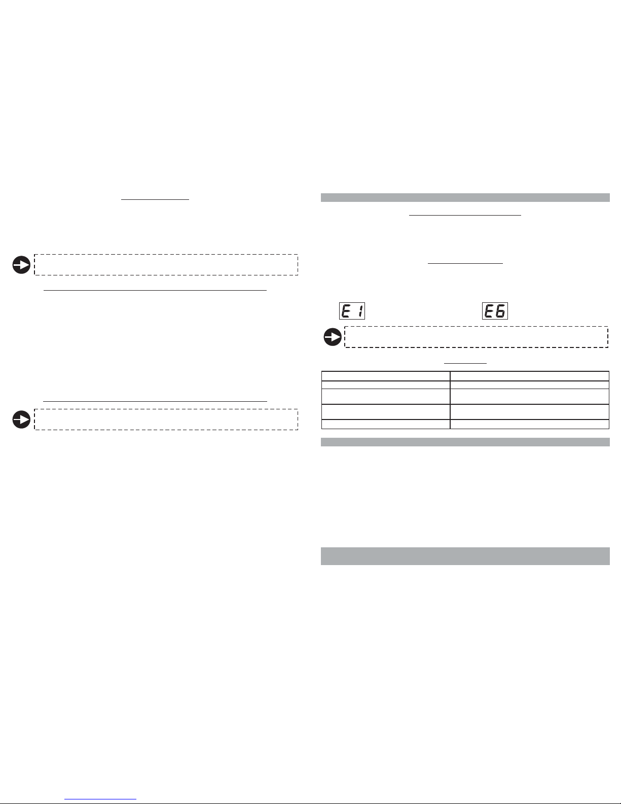
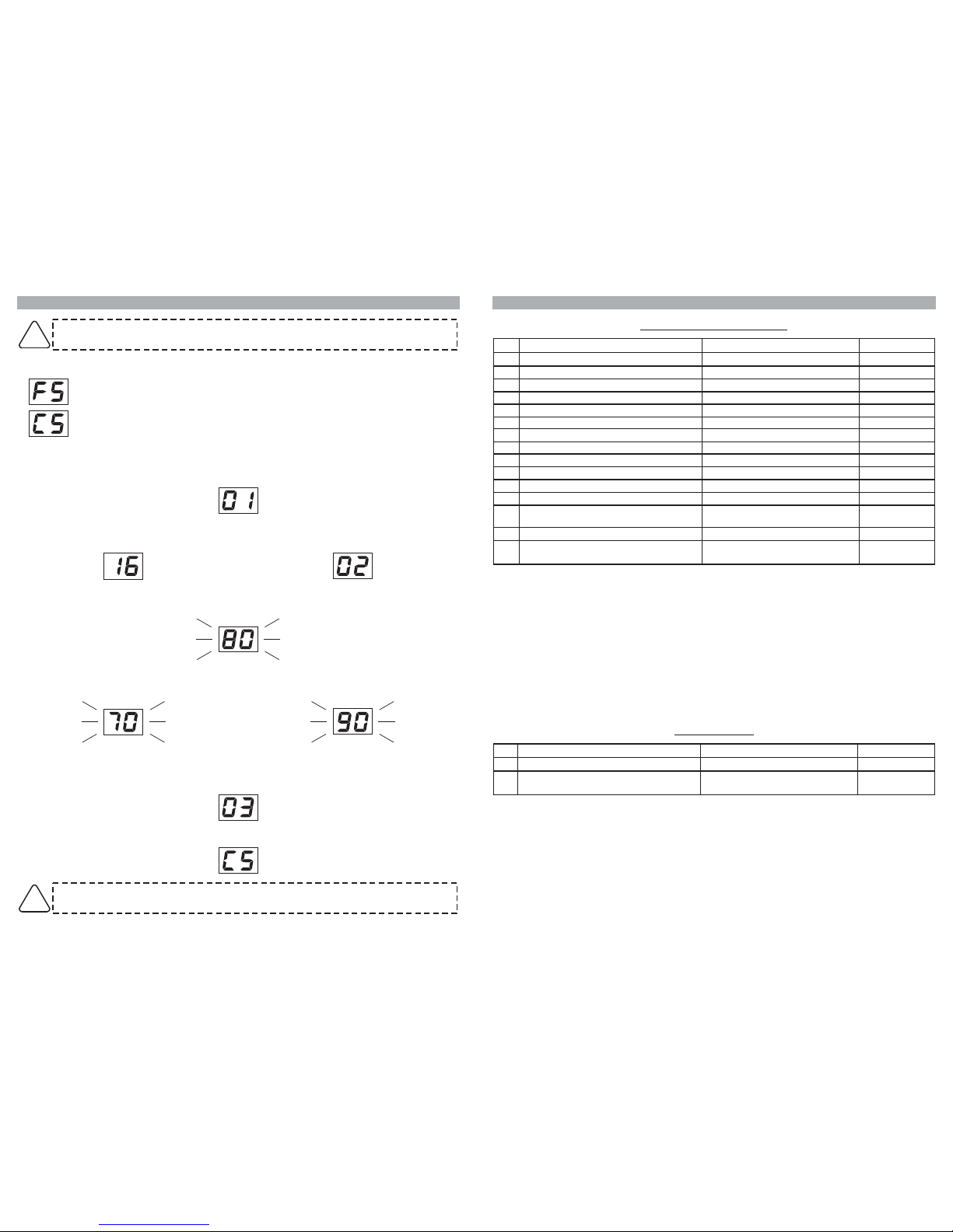
3.0 - TROUBLESHOOTING GUIDE
Sensor 1
inoperative.
Sensor 6
inoperative.
One single faulty sensor alters the correct functioning of the whole
parking system.
3.3 - OTHERS
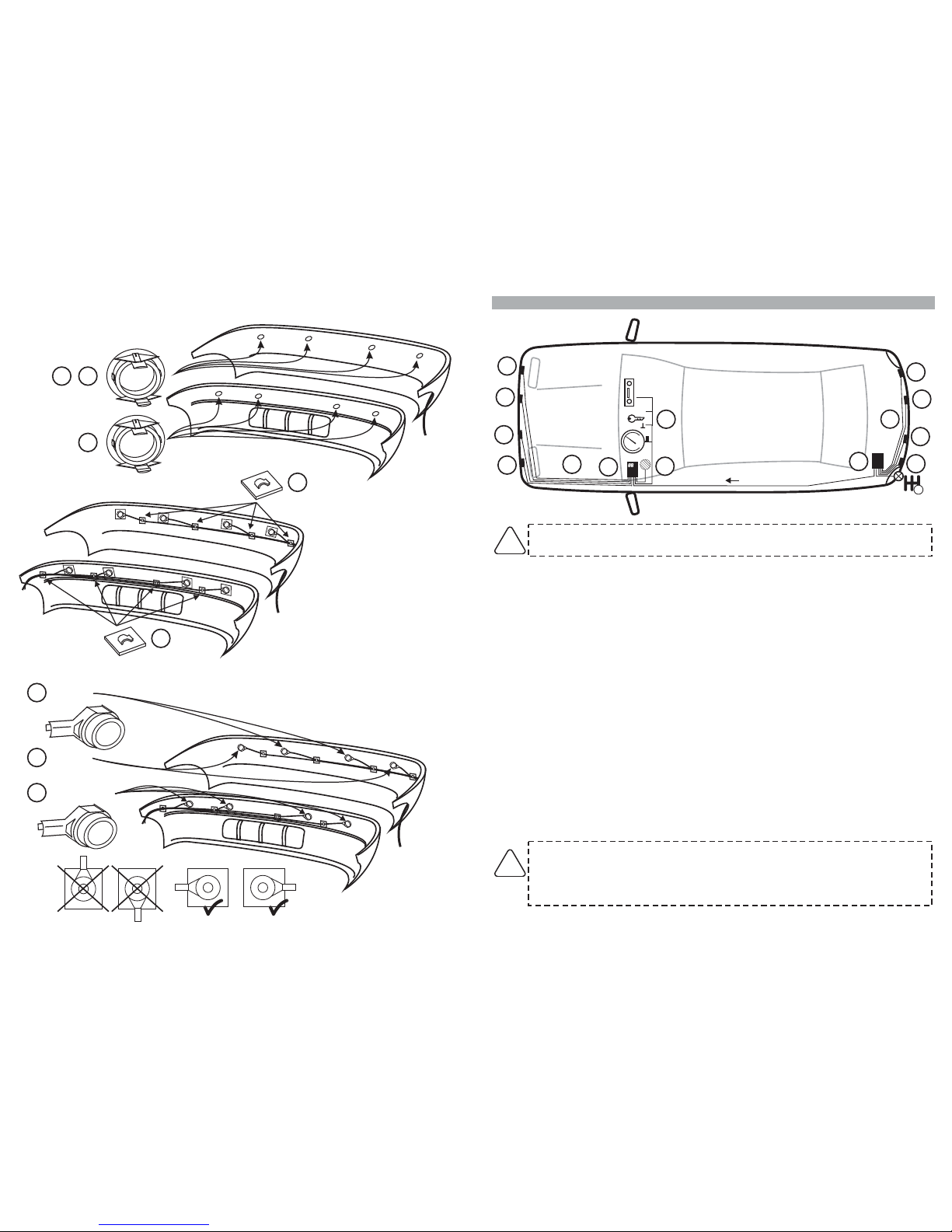
Ice on sensors
Sensors mounted too low
Back part of sensors in contact with frame
Sensors detect external spare wheel
POSSIBLE CAUSE
Clean the sensors
Use the angle brackets (9a or 12) to tilt axe of sensors
upwards
Create a separation between the sensors and the vehicle
(at least 2mm)
Modify the programming of parameter 10 (rear unit)
SOLUTION
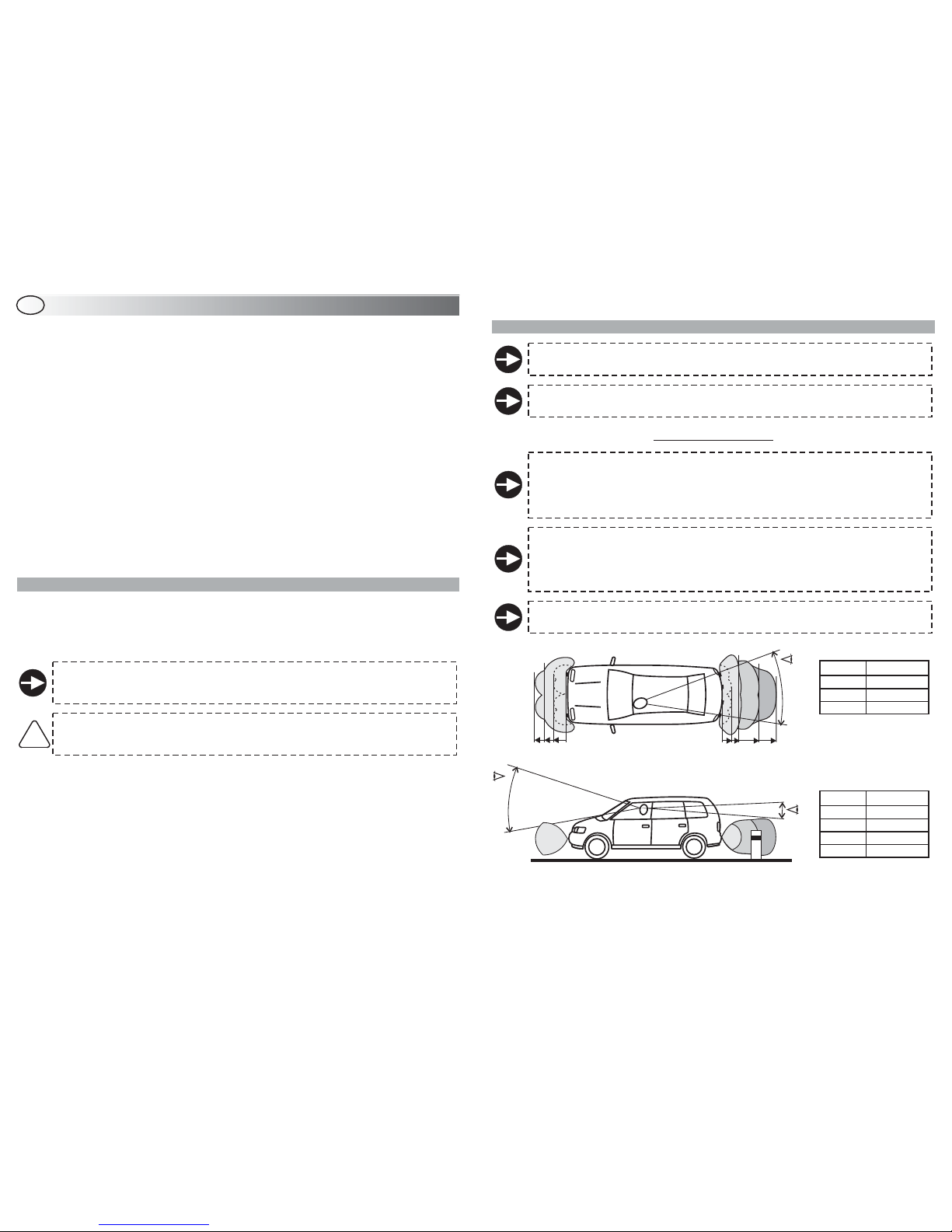
2.2 - REAR SENSORS
The rear sensors are activated when reverse gear is engaged; an audible signal
.
Detection of obstacles is signalled by the buzzer and the tone of the buzzer indicates in which
detection zone the obstacle is located.
.
warning will indicate
the sensors are active
The faster the beeping, the closer the obstacle; a continuous tone indicates the obstacle is extremely
close to the bumper
3.1 - LOW POWER SUPPLY SIGNAL
If, when the control unit is turned on, the battery level is too low to guarantee the accuracy of the
system, the buzzer will almost immediately give out a deep warning tone for 5”.
This will inform the user thatALLthe sensors are deactivated.
The driver will therefore know that he will have to do without the parking sensors.
3.2 - FAULTY SENSORS
If, when the control unit is turned on, one of the sensors turns out to be inoperative or not connected,an
audio signal will sound for 3”.
If more than one sensor is inoperative, the number of the faulty sensors will be alternatively displayed
on the front unit (main unit).
2.3 - AUTOMATIC ACTIVATION OF FRONT SENSORS (o )
When ignition is turned ON, the parking system becomes and
Short-pressed (about 1 sec.): sensors are deactivated until the button is pressed again.
Long-pressed (about 3 sec., you will hear a beep): sensors remain active until ignition is turned
OFF and ON again.
!
!
dometer signal
stays active as long as the vehicle
speed remains under approx. 15km/h (set odometer pulses according to vehicle, parameter 11).
At speeds above 15km/h, the front sensors are disabled and the LED turns off.
The LED turns ON to indicate that the sensors are activate and turns OFF when they are not in
operation.
Press the button with the LED to deactivate the sensors (ex. when in queue).
The push-button can be:
If the push-
button is long pressed (when sensors are only temporarily deactivated) they will be completely
disabled until ignition is turned ON again (ignition OFF-ON).
By means of a specific connection, the system functioning can be inhibited in case of
towing.
4.0 - WARRANTY CONDITIONS
This product is guaranteed to be free from defects in workmanship for a period of 24 months from the
date of installation reported on this warranty, in compliance with the 1999/44/CE Warranty Directive
(L. D. N° 24 of the 02/02/2002).
Please fill-in entirely the guarantee certificate included in this booklet and DO NOT REMOVE the
guarantee label from the device.
The warranty will become void if labels are missing or torn, if the installation certificate is not fully
compiled or if the enclosed sale document is missing.
The warranty is valid exclusively at authorized Gemini Technologies centers.
The manufacturer declines any responsability for eventual malfunctions of the parking sensors or any
damage to the vehicle electrical system due to improper installation, use or tampering.
The parking system is strictly a parking assist device, it should not be considered to be a safety device
for any purpose.
5.0 - WASTE ELECTRICAL AND ELECTRONIC EQUIPMENT
(WEEE) DIRECTIVE
The present device does not fall within the scope of Directive 2002/96/EC on Waste Electrical and
Electronic Equipment (WEEE) as specified in art. 2.1 of L.D. no. 151 of 25/07/2005.
The front sensors can be activated by turning the ignition ON or by pressing the push-button with the
LED.
Operation is parameters.
To activate the sensors through the push-button, press it at the beginning of the manoeuvre; once you
have parked, short press the push-button again to deactivate the sensors.
To deactivate the sensors totally, press and hold the button for at least 3 sec.; a beep confirms the
operation. They will remain switched off until the engine is turned OFF and ON again.
By modifying the of the front sensors (function 12, preset value “00”), the front sensors will
work as follows:
If, within the preset time, no obstacle is detected in front of the vehicle, the sensors will
automatically be deactivated.
If, within the preset time, the obstacle is still detected, the sensors will remain active as long as the
obstacle is detected and will deactivate 3” after detecting the last obstacle.
If you need to use the front sensors again after the automatic deactivation, simply press the push-
button with the LED.
The sensors will automatically deactivate 3” after detecting the last obstacle.
!
!
!
directly related to the setting of the
time setting
2.4 - TIME-ACTIVATED OF FRONT SENSORS ( not connected)odometer
Check setting of function 12 (delay in deactivation of front , “setting of
parameters”).
sensors