Helite SDUM0720201 User manual

Airbag certié / Certied airbag
Zertizierter Airbag / Gecerticeerde airbag
Airbag certicati / Airbag certicado
Sertisert airbag / Certikovaný airbag
Helite
www.helite.com
by Helite
1, rue de la petite n
21121 Fontaine-Lès-Dijon
OPTION FULL
PROTECTION
USER GUIDE / SDU FORK SENSOR
MANUEL D’UTILISATION / CAPTEUR FOURCHE SDU
BEDIENUNGSANLEITUNG / SDU-SATTEL-SENSOR
GUÍA DEL USUARIO / SENSOR DE HORQUILLA SDU
GUIDA UTENTE / SENSORE FORCELLA SDU.
UŽIVATELSKÁ PŘÍRUČKA / SDU SENZOR VIDLICE

Manuel d’utilisation
Bedienungsanleitung
User Guide
P3
P9
P15
Guía Del Usuario P21
Guida Utente P27
Uživatelská Příručka P33

MANUEL D’UTILISATION
Ici vous trouverez les informations concernant le capteur fourche (SDU).
Pour l’utilisation quotidienne de l’airbag, veuillez vous référer au manuel
d’utilisation qui accompagne votre airbag.
Ce manuel peut être amené à évoluer dans le temps, veuillez-
vous référer à la section du produit de notre site internet www.
helite.com pour obtenir la dernière version (numéro de version
indiquée à la n de ce manuel).
Le capteur fourche SDU est une option pour
les systèmes airbags électroniques. Il ne peut
pas être utilisé tout seul. Il faut toujours
l’associer à un airbag électronique Helite.
Les éléments du capteur ............................................................... 3
1ère utilisation ................................................................................. 4
Chocs et accidents détectés ........................................................ 6
Autonomie ................................................................................... 7
Entretien ...................................................................................... 7
Garantie & SAV ............................................................................ 8
Avis de non-responsabilité ........................................................... 8
1. Les éléments du capteur
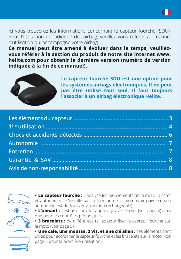
yLe capteur fourche : il analyse les mouvements de la moto. Discret
et autonome, il s’installe sur la fourche de la moto (voir page 5). Son
autonomie est de 5 ans environ (non rechargeable).
yL’aimant : il est utile lors de l’appairage avec le gilet (voir page 4) ainsi
que pour les contrôles périodiques.
y3 bracelets : de diérentes tailles pour xer le capteur fourche sur
la moto (voir page 5)
yUne cale, une mousse, 2 vis, et une clé allen : ces éléments sont
utiles pour accrocher le capteur fourche et les bracelets sur la moto (voir
page 5 pour la première utilisation)
A
A
A
A
A
A

Manuel d’utilisation
4
2. Première utilisation
Voici les étapes à suivre, avant la première utilisation de votre système airbag
électronique, si vous choisissez l’option capteur fourche «full protection».
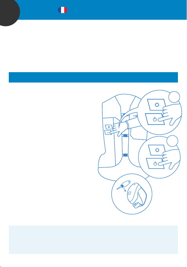
A. Associer le capteur fourche et le gilet
Tout d’abord, il faut appairer le gilet avec le capteur fourche. Pour cette manipulation
vous avez besoin du gilet, du capteur fourche et de l’aimant.
1. Allumer le gilet en appuyant
rapidement 3 fois sur le bouton. La LED
clignote vert et un bip se fait entendre.
2. Appuyer pendant 3 secondes sur le
bouton jusqu’à ce que la LED devienne
bleue. Relâcher le bouton et passer à
l’étape suivante.
3. Poser l’aimant sur le capteur
fourche au niveau du rond. Attention
vous avez 30 secondes pour eectuer cette
manipulation.
ySi un bip long se fait entendre sur le gilet
: votre gilet et le capteur fourche se sont
reconnus. Ils sont associés.
ySi c’est un bip court : le capteur fourche
était déjà reconnu par le gilet. Les 2
capteurs étaient déjà associés.
ySi plusieurs bips se font entendre (+ LED
rouge) : l’appairage a échoué. Soit vous
avez mis plus de 30 secondes à poser
l’aimant sur le capteur, soit vous avez
déjà 5 capteurs fourche associés au
gilet. Dans le premier cas, recommencez
la procédure d’appairage. Dans le
deuxième cas, vous devez eacer tous
les capteurs associés au gilet (voir page 7).
A SAVOIR :
yOn peut associer plusieurs capteurs fourche à un gilet (5 maximum). Il faudra
refaire cette manipulation d’appairage pour chaque capteur. Il peut être utile
d’avoir plusieurs capteurs fourches si vous avez plusieurs motos.
Attention : Vérier que la e-cartouche soit bien vissée et branchée au gilet.
x3
3sec

5
Manuel d’utilisation
yPour eacer tous les capteurs associés au gilet, appuyer pendant 8 secondes
sur le bouton de la veste.
yOn peut associer autant de gilets souhaités à un capteur.
yUn conducteur et son passager peuvent utiliser le même capteur fourche.
Pour vérier que votre gilet reconnaît bien le capteur fourche, il sut de
poser l’aimant sur le capteur fourche. Un bip sonore court au niveau du
gilet montre qu’il reconnaît ce capteur et qu’ils sont associés.
B. Installer le capteur fourche sur la moto
1. Choisir la bonne taille de bracelet
Essayer les diérentes tailles en vous aidant du tableau ci-dessus. Le bracelet doit être
ajusté à la fourche de la moto. La vis doit pouvoir se visser dans l’écrou du bracelet.
2. Assembler le capteur et le bracelet
Clipper le côté large du bracelet sur le côté du
capteur fourche. Choisissez l’encoche A pour
ajuster le bracelet à la taille de la fourche de
votre moto.
3. Positionner le capteur :
Attention : Les gilets appairés au capteur
fourche doivent être éteints
Fourche Cale Mousse Encoche Bracelet Taille vis
35 mm A 1 35 mm
≥ 37 mm A 1 35 mm
≥ 40 mm A 2 35 mm
≥ 44 mm A 2 35 mm
≥ 48 mm A 2 35 mm
≥ 50 mm A 2 50 mm
≥ 53 mm A 3 50 mm
A
A
Attention : bien nettoyer la fourche avant d’installer le capteur.

Manuel d’utilisation
6
a) Placer le capteur sur le bas d’un des fourreaux de la fourche de
la moto. Vériez qu’aucun élément de la moto ne vienne toucher le
capteur même en roulant.
b) Ajouter la cale si besoin pour ajuster le capteur fourche.
c) Visser la vis à l’aide de la clé fournie. Ne pas serrer à plus de
1,5 Nm au risque de casser le capteur fourche (vous pouvez arrêter de
visser quand vous avez des dicultés à tourner le capteur avec la main).
C. Ajuster le gilet a votre taille
Il est impératif d’ajuster et de fermer correctement votre airbag pour être protégé :
pour le e-Turtle régler les sangles et fermer les trois clips / pour le e-GP Air fermer les
velcros.
3. Chocs et accidents détectés
En version autonome (sans capteur SDU), il est nécessaire que la moto circule à une
allure supérieure à 20km/h pour qu’une chute ou un accident soient détectés. Voici la
liste des accidents détectés :
- Moto percutant ou se faisant percuter par un obstacle conséquent (véhicule, mur,
poteau...) de face, de côté ou par l’arrière.
- Perte de contrôle de la moto (sans choc sur la moto) : glissade sur le côté ou chute
de la moto.
Lorsque le gilet est associé à un capteur SDU, la liste des accidents détectés est
étendue aux impacts dès 0 km/h (Ex: percussion à l’arrêt par un véhicule tiers).
De plus le temps de détection est divisé par 2.
NB : Chaque accident est diérent. Bien que le système de détection de crash Helite couvre
une large majorité de potentiels accidents, il existe toujours un risque non-nul de non
déclenchement, notamment dans les congurations suivantes :
- Absence de signal GPS (tunnel, parking souterrain ...)
- Vitesse trop faible (notamment en cas d’utilisation du gilet en version autonome)
- Chute à faible amplitude.

7
Manuel d’utilisation
4. Autonomie
Une fois installé et appairé correctement (voir page 5), le capteur fourche est
totalement autonome (durée de vie d’environ 5 ans). Il est en veille permanente et
se réveille uniquement en cas d’accidents. Vous n’aurez donc plus besoin de vous en
soucier. Nous vous conseillons toutefois de vérier régulièrement (environ 1 fois
par mois) l’état de marche de votre capteur. Positionner l’aimant sur l’emplacement
rond du capteur pour vérier si le capteur est encore actif et s’il est bien associé à
votre gilet. Cette manipulation doit s’eectuer dans un environnement de plus de 10°C.
A SAVOIR :
Pour eacer tous les capteurs associés au gilet, appuyer pendant 8 secondes sur le
bouton de la veste allumée.
5. Entretien
A. CONSIGNES DE SÉCURITÉ
- Ne jamais démonter les composants du capteur SDU et tenter d’ouvrir le capteur SDU.
- Placer toujours le capteur SDU sur la fourche de la moto (voir page 6)
- Vérier régulièrement la batterie en positionnant l’aimant devant l’emplacement rond
du capteur environ une fois par mois. Attention cette manipulation doit être faite dans un
environnement de plus de 10°C.
- Le SDU doit s’utiliser exclusivement dans une plage de températures comprises entre
-10 et + 45 °C. L’exposition prolongée du système à des températures inférieures à - 10 °C et
supérieures à 45 °C peut nuire au bon fonctionnement du système.
Attention : Le capteur du gilet est sensible aux mouvements brusques du corps :
n’exécutez pas volontairement des manoeuvres qui ne sont pas nécessaires à la
conduite normale de votre moto. De même, il est important de ne pas provoquer
intentionnellement de chocs sur le capteur fourche quand votre gilet est allumé.
Ces deux cas pourraient déclencher le gonage de l’airbag.
LED verte : batterie OK
LED rouge : batterie faible = il faut changer le
capteur
Bip sonore au niveau de la veste : le capteur
selle et le gilet sont associés.

Manuel d’utilisation
8
B. ENTRETIEN & RECYCLAGE
- Vous pouvez laisser le capteur sur votre moto toute l’année.
- Le boitier est imperméable et résistant aux diérentes températures.
- Ne pas jeter le capteur fourche dans votre poubelle ménagère. Apportez-le en
déchetterie ou rapportez-le à votre revendeur.
6. Garantie & SAV
A. REMPLACEMENT
Si vous rencontrez les problèmes décrits ci-après, consultez un vendeur ou contactez-
nous pour une réparation ou pour un remplacement du produit.
- le système airbag électronique allumé n’a aucune réaction lorsque vous passez
l’aimant devant le capteur.
- le capteur fourche SDU clignote rouge quand vous passez l’aimant devant le capteur
dans les 5 ans qui suivent l’achat.
Service après-vente :
Contactez-nous par mail : [email protected] ou par téléphone : +33(0) 3 80 35 48 26
B. GARANTIE
Le système airbag électronique avec l’option «full protection» est garanti 2 ans
renouvelable 2 ans si vous l’enregistrez dans les 3 mois qui suivent votre achat sur
my.helite.com.
7. Avis de non responsabilité
- Ce produit est « Certié CE (conformité au Règlement UE 2016/425) par ALIENOR
CERTIFICATION, Zone du Sanital, 21 Rue Albert Einstein CHATELLERAULT-
Franceorganisme notié n° 2754 ».
- Helite et ses distributeurs déclinent toutes responsabilités pour une installation ou un
usage incorrect du capteur fourche SDU Helite.
- Helite et ses distributeurs ne peuvent pas être tenus responsables si l’airbag ne se
gone pas.
- Toutes modications ou mauvaise utilisation du capteur fourche peut provoquer un
dysfonctionnement du système airbag électronique.
- Les systèmes airbags électroniques Helite ne détectent pas tous les accidents ni
toutes les chutes.
- En cas d’accident ou de chute le système airbag électronique réduit les forces
transmises à l’utilisateur mais ne garantit pas d’éviter des lésions corporelles ou un
décès.
Retrouvez toutes les informations d’utilisations du système airbag
électronique dans le manuel d’utilisation fourni avec l’airbag.

USER GUIDE
Here you will nd all information about the SDU fork sensor. For daily use
of the vest, please read the electronic airbag system user guide attached
to your vest.
This user guide may change over time, please refer to the product
section of our website www.helite.com for the latest version
(version number indicated at the end of this user guide).
The SDU fork sensor can be used optionally
for the electronic airbag systems. It must not
be used alone and always needs to be paired
with a Helite electronic airbag system.
The fork sensor elements ............................................................... 9
First use ......................................................................................... 10
Impacts and detected accidents ................................................. 12
Autonomy ................................................................................... 13
Maintenance ............................................................................... 13
Warranty & After sales service .................................................. 14
Disclaimer .................................................................................... 14
1. The fork sensor elements
yFork sensor: analyzes the movements of the motorcycle. Discreet
and autonomous, it needs to be installed on the motorcycle fork (see
page 12). The fork sensor has an autonomy of around 5 years (not
rechargeable).
yMagnet: used to pair vest and fork sensor (see page 10) and also for
periodic control.
y3 bracelets: of dierent sizes to attach the fork sensor to the
motorcycle (see page 11).
y1 shim, 1 foam, 2 screws, and 1 Allen key: you need these
elements to install the fork sensor on the motorcycle (see page 11 for
rst use).
A
A
A
A
A
A

User Guide
10
2. First use
Please follow the steps below before using your electronic airbag system if you have
purchased the option “full protection” with the fork sensor.
A. Pair the fork sensor and the vest
Before using your vest for the rst time, you need to pair (i.e. associate) the vest with
the fork sensor. To do so, you need your vest, the fork sensor and the magnet.
1. Switch on the vest by pressing three
times the button quickly. The LED ashes
green and you hear a beep.
2. Press the button for 3 seconds until
the LED turns blue. Release the button and
go to the next step.
3. Place the magnet on the fork sensor
over the round slot. Please note that you
only have 30 seconds to eect this
procedure.
yIf you hear a long beep: the vest and the
fork sensor are paired.
yIf you hear a short beep: the vest and the
fork sensor have already been paired.
yIf you hear several beeps (+ red LED): the
pairing has failed. Either you have taken
more than 30 seconds to place the
magnet over the sensor, or you already
have 5 fork sensors associated with the
vest. In the rst case, repeat the pairing
procedure. In the second case, you must
delete all sensors associated with the
vest (see page 13).
GOOD TO KNOW:
yIt is possible to pair several fork sensors with one vest (5 maximum). For
example, if you have several motorcycles, the pairing process has to be done
for each motorcycle.
yTo delete all the sensors that are paired with the vest, press the button on
the vest for 8 seconds.
Caution: Check that the e-cartridge is properly screwed and connected to the vest.
x3
3sec

11
User Guide
yIt is possible to pair as many vests as you like with one fork sensor.
yRider and pillion rider can use the same fork sensor.
To check if your vest has recognized the fork sensor, you just need to
place the magnet on the fork sensor. A short beep on the vest indicates
that it is recognizing the sensor and that the fork sensor and the vest
are connected.
B. Install the fork sensor on the motorcycle fork
1. Choose the right bracelet size
Try the dierent sizes referring to the table above. The right size has to be adjusted to
the motorcycle fork. The screw needs to be screwed into the nut of the bracelet.
2. Assemble the sensor and the bracelet
Clip the wide side of the bracelet to the side of
the fork sensor. Choose notch A to adjust the
bracelet to the size of your motorcycle fork.
3. Place the sensor
Caution: If other vests are paired to the
sensor, they must be switched o.
Fork Shim Foam Notch Bracelet Screw size
35 mm A 1 35 mm
≥ 37 mm A 1 35 mm
≥ 40 mm A 2 35 mm
≥ 44 mm A 2 35 mm
≥ 48 mm A 2 35 mm
≥ 50 mm A 2 50 mm
≥ 53 mm A 3 50 mm
A
A
Caution: Make sure to thoroughly clean your fork before installing the sensor.

User Guide
12
a) Place the sensor on the bottom of one of the fork sleeves of the
motorcycle. Please check that no part of the motorcycle comes into
contact with the sensor while riding.
b) Add the shim if necessary to adjust the fork sensor.
c) Tighten the screw by using the nut. Do not tighten more than 1.5 Nm
to avoid breaking the fork sensor (you can stop screwing when it gets
dicult to turn the bracelet with your hand).
C. Wear the vest
Adjust the straps of the vest and close the three clips (e-Turtle) or close the velcro
(e-GP Air) for proper airbag operation.
3. Impacts and detected accidents
For the autonomous version (without fork sensor) the minimum speed must be 20
km/h for a fall or accident to be detected. Here are the possible detection cases:
- Motorcycle striking or being struck by a signicant obstacle (vehicle, wall, post, etc.)
from the front, side or rear.
- Loss of control of the motorcycle (without impact on the motorcycle): Slipping on the
side or falling o the motorcycle.
When the vest is associated with the fork sensor, the list of detected accidents is
extended to impacts from 0 km/h on (e.g. impact when stopped by a third party vehicle).
Additionally, the detection time is divided by 2.
Please note that each accident is dierent. Even though the Helite crash detection system
covers a large majority of potential accidents, there is always a non-zero risk of non-
triggering, especially in the following situations:
- Lack of GPS signal (tunnel, underground parking, etc.)
- Speed too low (especially when using the vest in autonomous version)
- Low-amplitude fall.

13
User Guide
4. Autonomy
Once installed and correctly paired (see rst use, page 10), the fork sensor is totally
autonomous (about 5 years). It is constantly in sleep mode and only wakes up if
an accident is detected. It is not necessary to take care of it often after installation.
We recommend to check on a regular base (once a month) if the fork sensor is
working properly. Place the magnet over the round sign of the fork sensor to check
that the fork sensor is still activated and that paired with the vest. Please note that this
check should be done in an environment of more than 10°C.
GOOD TO KNOW: To delete all the sensors that are paired with the vest, press
the button on the vest for 8 seconds.
5. Maintenance
A. SAFETY ADVICES
- Never disassemble the components of the fork sensor & open the fork sensor.
- Always place the sensor on the motorcycle fork (see page 12).
- Check the battery regularly (once a month) by placing the magnet over the round sign
on the saddle sensor. Please note that this check should be done in an environment of
more than 10°C.
- The fork sensor must only be used in a temperature range between -10 and + 45°C.
Prolonged exposure of the system to temperatures below -10° C and above 45° C may
impair the proper functioning of the system.
Caution: The vest sensor is sensitive to sudden body movements.
Do not intentionally execute movements that are not necessary for normal
motorcycle riding. It is equally important to not intentionally cause shocks to
the fork sensor when your vest is on. Both of these cases could trigger and
consequently inate the airbag.
Green LED: Battery OK
Red LED: Battery low = you need to change the
sensor
A beep sound on the vest:
the fork sensor and the vest are paired

User Guide
14
B. MAINTENANCE & RECYCLING
- You can leave the sensor on your motorcycle all year round.
- The SDU fork sensor is waterproof and resistant to dierent temperatures.
- Do not throw the fork sensor in your bin. Bring it to a dump or bring it to your dealer.
6. Warranty & After sales service
A. EXCHANGE
If you encounter any of the problems described below, please contact a dealer or
contact us for repair or exchange of the product:
- the activated (switched on) vest does not show any reaction when you place the
magnet over the sensor.
- the SDU fork sensor ashes red when you place the magnet over the round sign
during the rst 5 years of purchase.
After sales service:
Contact us via mail: [email protected] or via telephone: +33(0) 3 80 35 48 26
B. WARRANTY
The electronic airbag system with the option “full protection” comes with a 2 year
warranty. You can extend the warranty by 2 years if you register the product within 3
months after your purchase at my.helite.com.
7. Disclaimer
- This product is “CE certied (compliance with EU Regulation 2016/425) by
ALIENOR CERTIFICATION, Zone du Sanital, 21 Rue Albert Einstein CHATELLERAULT
Franceorganisme notié n° 2754“.
- Helite and its distributors refuse any responsibility for an incorrect installation or use
of the Helite SDU fork sensor.
- Helite and its distributors cannot be held responsible if the airbag does not inate.
- Every modication or incorrect use of the fork sensor can lead to a malfunctioning of
the electronic airbag system.
- Helite electronic airbag systems do not detect all accidents and falls.
- In the event of an accident or a fall, the electronic airbag system reduces the forces
transmitted to the user but does not guarantee to prevent personal injury or death.
Find all information about the use of the electronic
airbag system in the user guide delivered with your vest.

BEDIENUNGSANLEITUNG
Hier nden Sie alle Informationen zu dem Gabel-Sensor (SDU). Für den
täglichen Gebrauch des Airbag-Systems lesen Sie bitte die beigefügte
Bedienungsanleitung Ihres elektronischen Airbag-Systems.
Die Bedienungsanleitung kann mit der Zeit geändert werden.
Die neueste Version nden Sie im Produktbereich unserer
Website www.helite.com (die Versionsnummer ist am Ende dieser
Bedienungsanleitung angegeben).
Der SDU Gabel-Sensor wird optional für die
elektronischen Airbag-Systeme genutzt. Er
darf nicht alleine verwendet werden und
muss immer mit einem elektronischen Helite
Airbag-System gekoppelt sein.
Die Sensor-Elemente ................................................................... 15
Erstgebrauch ................................................................................. 16
Aufprall- und Unfallerkennung ................................................. 18
Lebensdauer ................................................................................ 19
Wartung ........................................................................................ 19
Garantie & Kundenservice ...................................................... 20
Haftungsausschluss .................................................................... 20
1. Die Sensor-Elemente
yGabel-Sensor: analysiert die Bewegungen des Motorrads. Er ist
autonom und wird an der Motorradgabel befestigt (siehe S. 17). Der
Sensor hat eine Lebensdauer von 5 Jahren (nicht wiederauadbar).
yMagnet: dient dazu, die Weste mit dem Gabel-Sensor zu koppeln
(siehe S. 16) und die Aktivität des Sensors zu überprüfen.
y3 Befestigungsvorrichtungen: in mehreren Größen verfügbar, zur
Befestigung des Gabel-Sensors am Motorrad (siehe S. 17).
y1 Keil, 1 Gummistreifen, 2 Schrauben und 1 Inbusschlüssel:
werden benötigt, um den Gabel-Sensor an der Motorradgabel zu
befestigen (siehe S. 17 zum Erstgebrauch).
A
A
A
A
A
A

Bedienungsanleitung
16
2. Erstgebrauch
Führen Sie vor der ersten Verwendung Ihres elektronischen Airbag-Systems
folgende Schritte aus, wenn Sie sich für die Variante „Full Protection“ mit Gabel-
Sensor entschieden haben.
A. Koppeln Sie den Gabel-Sensor mit der Weste
Zunächst müssen Sie die Weste mit dem Gabel-Sensor koppeln. Hierzu benötigen Sie
die Weste, den Gabel-Sensor und den Magneten.
1. Schalten Sie die Weste an, indem Sie
schnell auf den Knopf drücken. Die LED
blinkt grün und es ertönt ein Piepton.
2. Halten Sie den Knopf für 3 Sekunden
gedrückt bis die LED blau wird. Lassen Sie
den Knopf los und gehen Sie zum nächsten
Schritt über.
3. Platzieren Sie den Magneten am
Gabel-Sensor über dem runden Symbol.
Bitte beachten Sie, dass Sie nur 30 Sekunden
haben, um diesen Vorgang abzuschließen.
yLanger Piepton: Die Weste und der Gabel-
Sensor sind miteinander gekoppelt.
yKurzer Piepton: Die Weste und der Gabel-
Sensor wurden bereits miteinander
gekoppelt.
yMehrere Pieptöne (+ rote LED): Die
Kopplung ist fehlgeschlagen. Entweder
haben Sie mehr als 30 Sekunden
gebraucht, um den Magneten über den
Sensor zu platzieren, oder Sie haben
bereits 5 Gabel-Sensoren, die mit der
Weste verbunden sind. Wiederholen Sie
im ersten Fall den Kopplungsvorgang.
Im zweiten Fall müssen Sie alle mit der
Weste verbundenen Sensoren löschen (siehe S. 19).
GUT ZU WISSEN:
ySie können mehrere Gabel-Sensoren mit einer Weste koppeln (maximal 5).
Wenn Sie z.B. mehrere Motorräder haben, müssen Sie den Kopplungsvorgang
für jedes Motorrad einzeln abschließen.
Achtung: Überprüfen Sie, dass die e-Kartusche korrekt eingeschraubt und mit der
Weste verbunden ist.
x3
3sec

17
Bedienungsanleitung
yUm alle mit der Weste gekoppelten Sensoren zu löschen, halten Sie den Knopf
für 8 Sekunden gedrückt.
ySie können beliebig viele Westen mit einem Gabel-Sensor koppeln.
yFahrer und Sozius können den gleichen Gabel-Sensor nutzen.
Um zu überprüfen, ob Ihre Weste den Gabel-Sensor erkannt hat, halten
Sie den Magneten an diesen. Ein kurzer Piepton in Höhe der Weste zeigt
an, dass die Weste den Sensor erkannt hat und mit ihm gekoppelt ist.
B. Installation des Gabel-Sensors an der Motorradgabel
1. Wählen Sie die richtige Größe der Befestigungsvorrichtung
Testen Sie die verschiedenen Größen anhand der oben erwähnten Tabelle. Die richtige
Größe muss an die Motorradgabel angepasst werden. Die Schraube muss in die
Gewindemutter der Befestigungsvorrichtung
eingeschraubt werden.
2. Montieren Sie den Sensor mit der
Befestigungsvorrichtung
Klemmen Sie die breite Seite der
Befestigungsvorrichtung an die Seite des
Gabel-Sensors. Wählen Sie die Kerbe
A, um die Vorrichtung an die Größe der
Motorradgabel anzupassen.
3. Platzieren Sie den Sensor
Achtung: Bereits gekoppelte Westen müssen ausgeschaltet sein.
A
A
Gabel Keil Gummi-
streifen
Kerbe Vorrich-
tung
Größe der
Schraube
35 mm A 1 35 mm
≥ 37 mm A 1 35 mm
≥ 40 mm A 2 35 mm
≥ 44 mm A 2 35 mm
≥ 48 mm A 2 35 mm
≥ 50 mm A 2 50 mm
≥ 53 mm A 3 50 mm
Achtung: Reinigen Sie vor der Installation die Motorradgabel gründlich.

Bedienungsanleitung
18
a) Platzieren Sie den Sensor unten an einer der Gabelholme des
Motorrads. Stellen Sie sicher, dass auch während der Fahrt kein Teil
des Motorrads den Sensor berührt.
b) Nutzen Sie, falls nötig, die Unterlegscheibe, um den Gabel-Sensor
anzubringen.
c) Ziehen Sie die Schraube mit der Mutter fest. Ziehen Sie die Schraube
nicht mehr als 1,5 Nm an, da sonst der Gabel-Sensor brechen könnte.
Sie können mit dem Schrauben aufhören, wenn es schwierig wird, die
Befestigungsvorrichtung mit der Hand zu drehen.
C. Tragen der Weste
Passen Sie die Einstellriemen der Weste an und schließen Sie die Clips (e-Turtle)
oder den Klett (e-GP Air) für eine ordnungsgemäße Funktion des Airbag-Systems.
3. Aufprall- und Unfallerkennung
Bei der autonomen Variante (ohne Gabel-Sensor) ist eine Geschwindigkeit von
mindestens 20 km/h notwendig damit das System einen Sturz oder einen Unfall
erkennt. Hier sind die möglichen Unfall-Situationen, die erfasst werden:
- Motorrad, das von vorne, von der Seite oder von hinten auf ein bedeutendes Hindernis
(Fahrzeug, Wand, Pfosten usw.) aufschlägt oder von einem solchen getroen wird.
- Kontrollverlust über das Motorrad (ohne Aufprall auf das Motorrad): Auf der Seite
Ausrutschen, Sturz vom Motorrad oder High-Side.
Ist die Weste mit dem Gabel-Sensor gekoppelt, so werden auch Unfälle ab 0 km/h
erfasst (z.B. Aufprall beim Anhalten durch ein fremdes Fahrzeug). Der Sensor teilt die
Erkennungszeit durch 2.
Bitte beachten Sie, dass jeder Unfall anders verläuft. Auch wenn das Unfall-Erkennungssystem von Helite die
große Mehrheit der potentiellen Unfälle abdeckt, besteht immer das Risiko einer Nichtauslösung,
insbesondere in den folgenden Situationen:
- Schwaches GPS-Signal (Tunnel, Tiefgarage etc)
- Zu geringe Geschwindigkeit (insbesondere bei Verwendung der Weste in der autonomen Variante)
- Schwingungen, Ausschlag zu schwach.

19
Bedienungsanleitung
4. Lebensdauer
Nach der Installation und korrekten Kopplung (siehe Erstgebrauch, S. 16), ist der Gabel-
Sensor vollkommen autonom (Lebensdauer ca. 5 Jahre). Er bendet sich im
Schlafmodus und aktiviert sich nur im Falle eines Sturzes. Wir empfehlen eine
regelmäßige Kontrolle (einmal im Monat) des Sensors. Halten Sie den Magneten
über das runde Symbol des Sensors, um zu überprüfen, ob der Sensor noch aktiviert
und mit der Weste gekoppelt ist. Bitte beachten Sie, dass diese Überprüfung in einer
Umgebung von über 10°C vorgenommen werden sollte.
GUT ZU WISSEN: Um alle mit der Weste gekoppelten Sensoren zu löschen,
halten Sie den Knopf für 8 Sekunden gedrückt.
5. Wartung
A. SICHERHEITSHINWEISE
- Bauen Sie niemals die Komponenten des Gabel-Sensors auseinander.
- Önen Sie niemals den Gabel-Sensor.
- Platzieren Sie den Sensor immer an der Motorradgabel (siehe S. 18).
- Überprüfen Sie die Batterie regelmäßig (einmal im Monat), indem Sie den Magneten
über das runde Symbol am Gabel-Sensor halten. Bitte beachten Sie, dass diese
Überprüfung in einer Umgebung von über 10°C vorgenommen werden sollte.
- Der Gabel-Sensor darf nur in einem Temperaturbereich zwischen -10 und + 45°C
verwendet werden. Wird das System über längere Zeit Temperaturen von bis zu -10° C
und über 45° C ausgesetzt, kann es zu einer Beeinträchtigung der ordnungsgemäßen
Funktion des Systems kommen.
Achtung: Der CDU-Sensor in der Weste reagiert empndlich auf plötzliche
Körperbewegungen. Führen Sie nicht absichtlich Bewegungen aus, die für das
normale Motorradfahren nicht erforderlich sind.
Es ist ebenso wichtig, dass Sie den Gabel-Sensor bei angezogener Weste nicht
absichtlich Erschütterungen aussetzen.
In beiden Fällen könnte das Airbag-System auslösen.
Grüne LED: Batterie OK
Rote LED: Batterie schwach = Sie müssen den
Sensor wechseln.
Piepton an der Weste: Gabel-Sensor und Weste
sind gekoppelt.

Bedienungsanleitung
20
B. WARTUNG & RECYCLING
- Sie können den Sensor das ganze Jahr über an dem Motorrad lassen.
- Der Gabel-Sensor ist wasserdicht und gegen Temperaturunterschiede beständig.
- Werfen Sie den Gabel-Sensor nicht in den Hausmüll. Bringen Sie den Sensor zu einer
Deponie oder zu Ihrem Händler.
6. Garantie & Kundenservice
A. QUALITÄT
Sollte trotz regelmäßiger und sorgfältiger Qualitätskontrollen einer der unten
beschriebenen Fälle auftreten, kontaktieren Sie bitte Ihren Fachhändler oder unseren
Kundenservice.
- das angeschaltete elektronische System zeigt keine Reaktion, wenn Sie den Magneten
über den Sensor halten.
- der Gabel-Sensor leuchtet rot, wenn Sie den Magneten in den ersten 5 Jahren nach
dem Kauf über das rote Symbol halten.
Kundenservice:
Kontaktieren Sie uns per E-Mail: [email protected] oder Telefon: 02293-938632-0
B. GARANTIE
Das elektronische Airbag-System mit der Variante „Full Protection“ hat eine Garantie
von 2 Jahren. Wenn Sie das System innerhalb von 3 Monaten nach Kaufdatum unter
www.helite.de/Garantie registrieren, verlängert sich die Garantie für den Airbag auf 4
Jahre.
7. Haftungsausschluss
- Dieses Produkt ist „CE zertiziert (Konformität mit der EUVerordnung 2016/425) von
ALIENOR CERTIFICATION, Zone du Sanital, 21 Rue Albert Einstein CHATELLERAULT
Frankreich- organisme notié n° 2754“.
- Helite und Helite Importeure übernehmen keine Verantwortung oder Haftung bei
einer falschen Installation oder Verwendung des Gabel-Sensors.
- Helite und Helite Importeure können nicht dafür verantwortlich gemacht werden,
wenn das Airbag-System nicht auslöst.
- Jegliche Änderung oder falscher Gebrauch des Gabel-Sensors kann zu einer
Fehlfunktion des Airbag-Systems führen.
- Die elektronischen Airbag-Systeme von Helite erkennen nicht alle Unfälle oder Stürze.
- Im Falle eines Unfalls oder Sturzes reduziert das elektronische Airbag-System die auf
den Benutzer übertragenen Kräfte, garantiert aber nicht, dass Verletzungen oder der
Tod von Personen verhindert werden.
Alle Informationen zum elektronischen Airbag-System nden Sie in der
Bedienungsanleitung, die mit Ihrer Weste geliefert wird.
Table of contents
Languages:
Other Helite Motorcycle Accessories manuals
Popular Motorcycle Accessories manuals by other brands

SW-Motech
SW-Motech TRT.00.787.32500/B Mounting instructions

LSL
LSL 556KT07 Series FITTING INSTRUCTION

SCHUBERTH
SCHUBERTH S2 manual

Suzuki
Suzuki 99180-48K10-GRY installation instructions

Dynojet
Dynojet Power commander V installation instructions

Suzuki
Suzuki 99143-00A1 000 Series installation instructions