gen2 OTIS OI-6940-NXP Series User manual


CAUTION
CAUTION: FOR SAFETY REASONS, THIS EQUIPMENT MUST BE OPERATED AND
SERVICED BY QUALIFIED PERSONNEL ONLY. READ AND UNDERSTAND THE
INSTRUCTION MANUAL COMPLETELY BEFORE OPERATING OR SERVICING.
DANGER
DANGER: OTIS INSTRUMENTS INC. OI-6940-X-X-NXP-X IS AN AMBIENT AIR TOXIC GAS
SENSOR ASSEMBLY AND ONLY MONITORS IN THE IMMEDIATE VICINITY OF THE
SENSOR HOUSINGS. A SITE SURVEY IS REQUIRED IN ORDER TO DETERMINE THE
BEST PLACEMENT AND QUANTITY OF SENSOR ASSEMBLIES. IMPROPER
INSTALLATION CAN LEAD TO AN UNDETECTABLE GAS LEAK WHICH COULD RESULT
IN PERSONAL INJURY OR LOSS OF LIFE.


TABLE OF CONTENTS
OI-6940-X-X-NXP OPS_GUIDE_REV 1.0 i
TABLE OF CONTENTS
1PRODUCT OVERVIEW..........................................................................................................................................1
1.1 INTRODUCTION ....................................................................................................................................................1
1.2 PRODUCT SPECIFICATIONS ...............................................................................................................................2
1.3 SYSTEM DIAGRAMS.............................................................................................................................................3
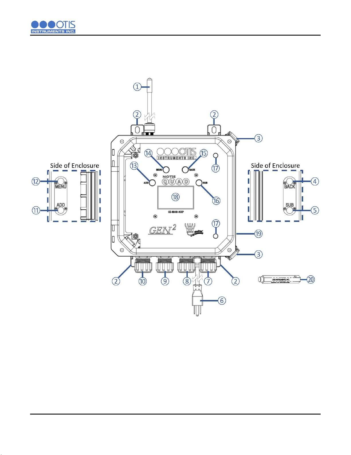
1.3.1 EXTERNAL SYSTEM DIAGRAM ...........................................................................................................................3
1.3.2 INTERNAL SYSTEM DIAGRAM.............................................................................................................................4
2INSTALLATION AND START-UP..........................................................................................................................5
2.1 PRODUCT PLACEMENT .......................................................................................................................................5
2.2 PRODUCT MOUNTING .........................................................................................................................................6
2.3 WIRING CONFIGURATIONS.................................................................................................................................6
2.3.1 OPENING THE ENCLOSURE................................................................................................................................6
2.3.2 CONNECTING AC POWER ...................................................................................................................................7
2.3.3 CONNECTING THE BATTERY PACK ...................................................................................................................8
2.3.4 CLOSING THE ENCLOSURE ................................................................................................................................8
2.4 SYSTEM START-UP ..............................................................................................................................................9
2.5 NORMAL OPERATING MODE.............................................................................................................................10
3PRODUCT SETTINGS AND CONFIGURATION .................................................................................................11
3.1 GLOBAL SETTINGS ............................................................................................................................................12
3.1.1 NETWORK ID.......................................................................................................................................................12
3.1.2 UNIT INFORMATION ...........................................................................................................................................13
3.1.3 DISPLAY SCREEN CONTRAST SETTING .........................................................................................................14
3.1.4 RETURN TO FACTORY DEFAULT SETTINGS ..................................................................................................15
3.1.5 BACK MENU ........................................................................................................................................................16
3.2 SENSOR SETTINGS............................................................................................................................................17
3.2.1 TURN SENSOR ON/OFF .....................................................................................................................................17
3.2.2 NULLING THE SENSOR (AUTO NULL) ..............................................................................................................18
3.2.3 CALIBRATING THE SENSOR (MANUAL CAL) ...................................................................................................20
3.2.4 CALIBRATING THE SENSOR (AUTO CAL) ........................................................................................................21
3.2.5 SENSOR RADIO ADDRESS................................................................................................................................24
3.2.6 SENSOR RELAY TEST........................................................................................................................................25
3.2.7 SENSOR BACKGROUND SETTING ...................................................................................................................26
3.2.8 SENSOR BACKGROUND HIGH SETTING .........................................................................................................27
3.2.9 SENSOR BACKGROUND LOW SETTING ..........................................................................................................28
3.2.10 CALIBRATION METHOD .....................................................................................................................................29
3.2.11 SENSOR INFORMATION ....................................................................................................................................30
3.2.12 NULL-CALIBRATION TIMER INFORMATION .....................................................................................................31
3.2.13 RESET SENSOR NULL/CAL................................................................................................................................32
3.2.14 BACK MENU ........................................................................................................................................................33
4OPERATION SETTINGS .....................................................................................................................................34
4.1 POWERING THE DEVICE ...................................................................................................................................34
4.1.1 POWERING ON ...................................................................................................................................................34
4.1.2 POWERING OFF..................................................................................................................................................34
4.2 DISPLAY BEHAVIOR ABOVE BACKGROUND ...................................................................................................35

TABLE OF CONTENTS
ii OI-6940-X-X-NXP OPS_GUIDE_REV 1.0
5PRODUCT MAINTENANCE.................................................................................................................................36
5.1 SCHEDULED MAINTENANCE.............................................................................................................................36
5.2SENSOR REPLACEMENT...................................................................................................................................37
5.3 BACKUP BATTERY REPLACEMENT..................................................................................................................38
5.4 PRODUCT FAULT CODES..................................................................................................................................39
5.5 PRODUCT REPLACEMENT PARTS AND ACCESORIES ..................................................................................40
APPENDIX A: PRODUCT WARRANTY STATEMENT.............................................................................................................42
APPENDIX B: INFORMATION ABOUT RMA SERVICE REPAIRS .........................................................................................44
APPENDIX C: INFORMATION ABOUT RMA RETURNS FOR CREDIT..................................................................................46

INSTALLATION AND START-UP
OI-6940-X-X-NXP OPS_GUIDE_REV 1.0 1
1 PRODUCT OVERVIEW
1.1 INTRODUCTION
The Otis Instruments, Inc. (Otis) GEN II Model OI-6940-X-X-NXP-X (OI-6940) Non-Explosion-Proof Ambient Air
Quad Toxic Gas Detector is designed to detect a wide range of toxic gases in many environments. The OI-6940
features non-intrusive magnetic switches that allow for complete system configuration, regular calibration, and
product maintenance to be performed in the field without opening the lid and breaking the seal of the enclosure. Non-
intrusive interface with the OI-6940 is made possible by use of the Otis Magnetic Tool included in the purchase of
the device.
The OI-6940 continuously monitors the gas level of the surrounding environment and reports once every minute, the
reporting rate will increase to once every five seconds when the detected gas is above the Background Gas set-
point. This set-point is adjustable, per sensor, to account for sites that may have a constant low level of gas always
present allowing the OI-6940 to maintain a long battery life (when not operating on AC power). When the gas level
drops below the set-point, for all sensors, the reporting rate will return to once every minute. The OI-6940 display
screen will always show the present concentration of gas being detected by the sensor assembly. More information
about the Background Gas Set-point is found later in this manual.
This document is an operation manual containing diagrams and step-by-step instructions for the proper and safe
installation, start-up, configuration and settings, normal operation, and product maintenance of the OI-6940.
In this manual, the instructions reference the use of push-buttons, located on the front panel of the device. In certain
environments, the activation of the non-intrusive magnetic switches, through the use of the Otis Magnetic Tool, will
replace the directive of the button-press actions. To apply the Otis Magnetic Tool, hold the tool to the side of the
device enclosure adjacent to the push-button that you wish to activate. When the magnetic switch is toggled, an on-
screen indicator will appear on the display screen, signifying that a connection was made.
NOTICE
This document should be read in its entirety before the initial operation of the product.
Should a question arise during the use of the product, this document will serve as a first reference for the end-user.
For inquiries beyond the information and instructions provided within this manual, contact the sales representative
of this product for assistance.

INSTALLATION AND START-UP
2 OI-6940-X-X-NXP OPS_GUIDE_REV 1.0
1.2 PRODUCT SPECIFICATIONS
System Specifications
Operating Voltage
100-240 VAC 0.35A Power Supply Input
3.3 VDC Power Supply Output
Battery Life
Up to 6 months, 45 days Max with VOC sensor installed (When used as primary power source)
Operating Temperature
Range
-40⁰C to +54⁰C
Humidity Range
0% to 98% Relative Humidity, Noncondensing
Measurement Range
Varies based on gas type
Response Time
Varies based on gas type
WireFree Option
GEN II 900 MHz –52 Networks, 255 Sensors per Network
GEN II 2.4 GHz –78 Networks, 255 Sensors per Network
RF Connection
N-Female Radio Frequency (RF) Connector
Display
Transflective (sunlight-readable)
160 X 104 LCD Screen
LED Back-Light
Interface
4 Push-Buttons (MENU, ADD, SUB, BACK)
4 Magnetic Switches for Non-Intrusive Calibration
Mechanical Specifications
Enclosure Materials
Fiberglass Device Enclosure with Clear Lid
Sensor Housing Material
Black Polypropylene Plastic with Stainless Steel Mesh Screen (Up to 4)
Product Dimensions
5" D x 10.5" W x 20" T (Max Dimensions w/ Antenna)

INSTALLATION AND START-UP
OI-6940-X-X-NXP OPS_GUIDE_REV 1.0 3
1.3 SYSTEM DIAGRAMS
Refer to the following diagrams for identification of the external and internal system components that may be referred
to in this manual.
1.3.1 EXTERNAL SYSTEM DIAGRAM
11 ADD Magnet Button Location
12 MENU Magnet Button Location
13 ADD Push Button
14 MENU Push Button
15 BACK Push Button
16 SUB Push Button
17 Front Panel Thumbscrew (2X)
18 Display Screen
19 Enclosure Lid (Clear)
20 Magnetic Tool
1Radio Antenna –900 MHz or 2.4 GHz
2Enclosure Mounting Foot (4X)
3Enclosure Latch (2X)
4BACK Magnet Button Location
5SUB Magnet Button Location
6AC Power Cord
7Sensor Housing Number 4
8Sensor Housing Number 3
9Sensor Housing Number 2
10 Sensor Housing Number 1

INSTALLATION AND START-UP
4 OI-6940-X-X-NXP OPS_GUIDE_REV 1.0
1.3.2 INTERNAL SYSTEM DIAGRAM
1Enclosure Lid (Clear)
2Front Panel
3Antenna Fitting Connector
4Radio Module –900Mhz or 2.4 GHz
5Backup Battery Pack Plug
6External Antenna Fitting
7AC Power Supply
8Terminal Board Assembly
9Backup Battery Pack
10 Battery Pack Restraining Strap
11 Sensor Housing Interface Boards –Up to 4
12 Sensor Housing Connector –Up to 4
13 Control Board Assembly

INSTALLATION AND START-UP
OI-6940-X-X-NXP OPS_GUIDE_REV 1.0 5
2 INSTALLATION AND START-UP
2.1 PRODUCT PLACEMENT
The installation instructions, and any other information supplied by Otis, provide only basic guidelines relating to the
properties of toxic gas and the effects of environmental conditions on the OI-6940 device. Sensor placement should
be determined in consultation with the site safety personnel, as well as those knowledgeable of: (1) the site/facility
where the equipment is being installed and (2) the potentially present gas types and their dispersion. Otis strongly
recommends that the end-user consults with the appropriate third party Health, Safety and Environmental (HSE) and
Industrial Hygiene (IH) professionals to determine the final quantity and placement of your gas detection devices.
The primary purpose of the OI-6940 is to provide an early warning of the accumulation of toxic gas, in order to
minimize hazards to people and property. Proper placement of the device is paramount to achieving this goal.
The following general guidelines should be considered when determining the placement of the OI-6940:
The unit should be placed greater than 6.5 Feet/2 Meters away from a monitor in order to ensure reliable
communications
The unit shall be placed such that the sensor housings are pointing downward to the ground.
Avoid installing the unit in a location where airborne particles could cover or coat the sensor head.
The unit should be placed in an area that will produce the highest gas concentration. Enclosed corners and
stopping points of moving devices are two areas susceptible to a buildup of toxic gas.
In order to provide an accurate representative sample of a room, care should be taken to avoid locating the
unit near a room entrance, fresh air intake vent, or vehicle/generator exhaust point.
The unit should be placed as close as physically possible to the source of the potential toxic gas leak.
Consider placing the unit in a seldom used area, such as a warehouse, storage area, or other unfrequented
location.
Consider accessibility for regular calibration and other required maintenance.
When monitoring a ventilated gas cylinder storage area, the unit should be placed near the air return vent.
When monitoring an outdoor open-air area, the unit should be placed near the air intake of the HVAC system
of the building.
When monitoring for the potential presence of multiple toxic gas types, the unit should be calibrated for the
least cross-sensitive toxic gas.
NOTICE
These guidelines are ONLY intended as a general directive for the placement of the OI-6940. This information
should NOT server as a complete list when considering all potential parameters for the proper location of the unit.
It is STRONGLY advised that a third party Certified Industrial Hygienist, or other Certified Safety Professional,
conduct a site survey and annotate the location and quantity of detection devices that should be installed for
EVERY installation of EVERY site.

INSTALLATION AND START-UP
6 OI-6940-X-X-NXP OPS_GUIDE_REV 1.0
2.2 PRODUCT MOUNTING
It is recommended to mount the unit to a solid structure (Such as a concrete wall, steel column, or angle iron) where
a minimum of vibration will be transmitted to the unit. Any style of bolt or screw may be used as long as it is steel
and meets or exceeds the following:
Maximum 1/4" diameter bolt or screw (length varies with user need)
Flat washers for bolts/nuts/screws
Minimum Grade 5 (or better)
Corrosion protection for all hardware (paint, galvanize, zinc plating, etc.)
2.3 WIRING CONFIGURATIONS
The OI-6940 is powered by an AC power supply with a non-rechargeable backup battery pack. The OI-6940 is fully
operational when using the backup battery pack and can be used in normal operation if an AC power source is
unavailable.
CAUTION
VERIFY that the power source is disabled before beginning the following wiring steps or performing any
maintenance inside the device enclosure.
The internal components can be static sensitive. Use caution when opening the enclosure and handling
internal components.
VERIFY that the label and color combination of the control board terminal exactly matches the
corresponding label and color combination of the power terminal.
OI-6940 Terminal Block Wire Gauges
Terminal Block
Wire Gauge
Power Terminal
Min: 26 AWG
Max: 14 AWG
AWG: American Wire Gauge
2.3.1 OPENING THE ENCLOSURE
To prepare the OI-6940 for installation, you must first open the device enclosure, exposing the control
board and its components for wiring.
1. Open the enclosure lid by releasing the two latches on the right side corners, and swinging the lid open.
2. Unscrew the two captive front panel thumbscrews and open the front panel in order to access the terminal
board mounted on the back plane.

INSTALLATION AND START-UP
OI-6940-X-X-NXP OPS_GUIDE_REV 1.0 7
2.3.2 CONNECTING AC POWER
The OI-6940 is shipped with an AC power cord for connection to a standard wall outlet supplying 120VAC.
An alternate AC power source connection can be used in place of the standard power cord, the
instructions below detail the wiring instructions if this change is desired.
On the GEN II Model OI-6940 Device:
1. Disconnect the existing AC power cord from the power supply and remove from the power cord grip
located on the bottom of the unit.
2. Feed the new power cable into the enclosure through the power cord grip.
3. Locate the power terminal block on the AC power supply and complete the following:
a. Connect the Supply (BLACK) wire to the “L (Line)” terminal.
b. Connect the Neutral (WHITE) wire to the “N (Neutral)” terminal.
c. Connect the Ground (GREEN) wire to the “G(Ground)”terminal.
POWER SOURCE
TERMINALS
OI-6940
POWER SUPPLY
TERMINALS
LINE
Black
LINE
Black
NEUTRAL
White
NEUTRAL
White
GROUND
Green
G
Green

INSTALLATION AND START-UP
8 OI-6940-X-X-NXP OPS_GUIDE_REV 1.0
2.3.3 CONNECTING THE BATTERY PACK
The OI-6940 is shipped with the battery pack installed but disconnected from the terminal board. The
battery pack is used as a backup supply in case of loss of AC power, but is also capable of fully operating
the OI-6940 if an AC power source is unavailable.
On the GEN II Model OI-6940 Device:
1. Plug the battery cable connector into the battery socket on the terminal board.
2.3.4 CLOSING THE ENCLOSURE
1. Close the faceplate and secure with the two captive thumbscrews.
2. Close the enclosure lid and secure with the latches on the right side.

INSTALLATION AND START-UP
OI-6940-X-X-NXP OPS_GUIDE_REV 1.0 9
2.4 SYSTEM START-UP
After power is applied, the unit will enter into OFF mode. Once the enclosure is properly closed you may turn the unit
on and begin its 1 minute, 3 ½ minutes when the Low Power Infrared sensor is installed, warmup period. During
warmup, the display will show a countdown of the time remaining until the system start-up is complete. The Otis logo
and the unit information will also show on the display screen during start-up.
At the end of the countdown, the device will be in normal operating mode.

INSTALLATION AND START-UP
10 OI-6940-X-X-NXP OPS_GUIDE_REV 1.0
2.5 NORMAL OPERATING MODE
During normal operating mode, the OI-6940 continuously samples the air and updates the measured concentration
of the target gasses on the display screen. The display, when in normal operation, appears as shown below.
1Battery Level Indicator (Only visible when backlight is off)
2Network ID the OI-6940 is transmitting on
3Sensor radio address (Each sensor has an address)
4Sensor reading (Each sensor has its own reading display)
5Sensor gas type (Each sensor is a different gas type)
6Gas concentration unit of measure
7Fault indication (Appears in place of Gas concentration unit of measure)
In the event of a device failure, the unit will display a fault code in place of the gas concentration unit of measure.
When the fault is corrected, the unit will return to normal operating mode and the gas concentration unit of measure
will be displayed again.
For a list of the fault codes of the OI-6940, and their associated meaning, refer to the Product Troubleshooting section
of this manual.
NOTICE
After 5 minutes of no interaction with the device, the unit will automatically return to normal operating mode.
⑦

OPERATION SETTINGS
OI-6940-X-X-NXP OPS_GUIDE_REV 1.0 11
3 PRODUCT SETTINGS AND CONFIGURATION
The product settings and configuration menus allow the end-user to tailor the device settings of the OI-6940 to meet their
required specifications and/or site conditions.
While the device is in normal operating mode, Press and Hold the MENU button, for approximately 6 seconds, until the
product settings and configuration menu is activated and open on the display screen.
The product settings and configuration menus consist of the following screens:
Global Settings
oNetwork I.D.
oInfo Screen
oContrast
oReturn to Factory Defaults
oBack
Sensor 1-4 Settings
oTurn Sensor On/Off
oNull Sensor
oCalibrate Sensor
oSensor Radio Address
oSensor Relay Test
oSensor Background Setting
oCalibration Method
oSensor Information
oLast Null/Cal Times
oReset Sensor Null/Cal
oBack
Exit

OPERATION SETTINGS
12 OI-6940-X-X-NXP OPS_GUIDE_REV 1.0
3.1 GLOBAL SETTINGS
Use the MENU button for SELECT to enter the Global Settings Menu, any settings under this menu option will affect
all aspects of the OI-6940. Use the ADD button for NEXT to advance to the Sensor 1 Settings menu. Use the SUB
button for PREV to move to the EXIT menu option. You can also use the BACK button on the OI-6940 to exit the
Product Settings and Configuration Menus.
3.1.1 NETWORK ID
The first option under the Global Settings Menu is to configure the Network I.D. of the OI-6940. The Network ID is
used to synchronize the communication between the Otis Monitor and OI-6940 assembly and must be set the same
to ensure successful communication.
Press the MENU button for SELECT to enter the Network I.D. setting menu. Use the ADD button for NEXT to
advance to the Information Screen Menu. Use the SUB button for PREV to move to the BACK menu option. You
can also use the BACK button on the OI-6940 to return back to the Main Product Settings and Configuration Menus.
1. After entering the Network I.D. Setting menu, press the ADD or SUB button until the Network ID
matches the value being used on the Primary Monitor.
2. Press the MENU or BACK button to return to the Global Settings Menu options.

OPERATION SETTINGS
OI-6940-X-X-NXP OPS_GUIDE_REV 1.0 13
3.1.2 UNIT INFORMATION
Press the MENU button for SELECT to enter the Information Screen menu. Use the ADD button for NEXT to advance
to the Screen Contrast Menu. Use the SUB button for PREV to move to the Network I.D. menu option. You can also
use the BACK button on the OI-6940 to return back to the Main Product Settings and Configuration Menus.
The unit information screen allows the end-user to view the following information:
The radio link status to the primary monitor
The radio In Range Status
Missed Radio Transmissions
The supply voltage of the OI-6940
The date of manufacture of the OI-6940.
The serial number of the OI-6940.
This screen is for informational purposes only.
1. Press the MENU or BACK button to return to the Global Settings Menu options.

OPERATION SETTINGS
14 OI-6940-X-X-NXP OPS_GUIDE_REV 1.0
3.1.3 DISPLAY SCREEN CONTRAST SETTING
Press the MENU button for SELECT to enter the Contrast Setting menu. Use the ADD button for NEXT to advance
to the Return to Factory Defaults menu option. Use the SUB button for PREV to move to the Information Screen
menu option. You can also use the BACK button on the OI-6940 to return back to the Main Product Settings and
Configuration Menus.
The display screen contrast is the difference in luminance or color that makes the displayed images distinguishable.
Due to varying external elements, such as extreme sunlight, the brightness of the display screen may need to be
adjusted for optimum viewing.
The factory defaults setting on the OI-6940 for the display screen is 150, approximately 58% of the contrast scale.
The contrast setting ranges from 0 to 255.
1. Use the ADD and SUB buttons to brighten and dim the contrast, respectively.
2. After the contrast is correctly set, press the MENU or BACK button to save your value and return to the Global
Settings Menu.
Table of contents
Popular Gas Detector manuals by other brands

Crowcon
Crowcon IRmax Installation, operating and maintenance instructions

Sensitron
Sensitron SMART S Installation and user manual

Xintex
Xintex G-1B-R Series Owner's Manual & Installation Instructions

Evikon
Evikon PluraSens E2608 Series user manual

PEMTECH
PEMTECH PT2000/H Series Operator's manual

Riken Keiki
Riken Keiki SD-1D-AS operating manual

Rielta
Rielta SH-VTG installation guide

Herth+Buss
Herth+Buss ELPARTS SelectH2 mini operating instructions

United Electric Controls
United Electric Controls UE VANGUARD WirelessHART TCD60HXY Installation and maintenance instructions

Uniphos
Uniphos ASP-40 instruction manual

Taichuan
Taichuan TC-U9AF-CO/Z installation instructions

Sensitron
Sensitron PATROL manual